
Related Manuals for Renesas R0E521000EPB00


Summary of Contents for Renesas R0E521000EPB00
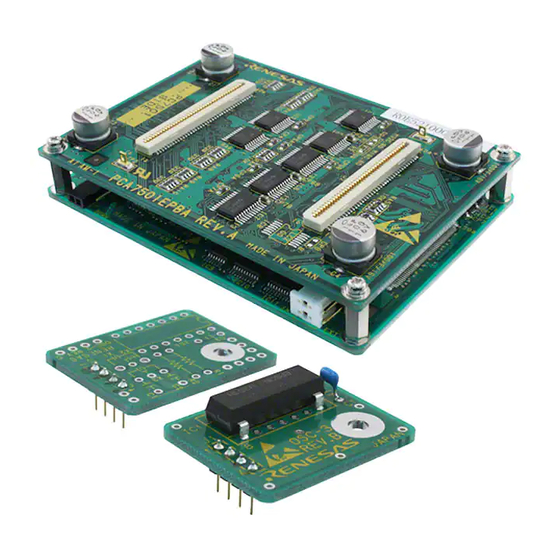
- Page 1 REJ10J0844-0400(T) R0E521000EPB00 User’s Manual Emulation Probe for R8C/Tiny Series Rev.4.00 Oct. 16, 2007...
-
Page 3: Preface
This user's manual mainly describes specifications of the R0E521000EPB00 emulation probe and how to setup it. For details on the following products, which are used with the R0E521000EPB00, refer to each product's user's manual or online manual. Emulator main unit:... -
Page 4: Important
The emulator herein does not include the customer’s user system and host machine. Purpose of use of the emulator: This emulator is a device to support the development of a system that uses the R8C/Tiny Series Renesas 16bit single-chip MCUs. It provides support for system development in both software and hardware. - Page 5 R0E521000EPB00 User’s Manual Important Usage restrictions: This emulator has been developed as a means of supporting system development by users. Therefore, do not use it as a device used for equipment-embedded applications. Also, do not use it for developing the systems or equipment used for the following...
-
Page 6: Precautions For Safety
R0E521000EPB00 User’s Manual Precautions for Safety Precautions for Safety Definitions of Signal Words In both the user’s manual and on the product itself, several icons are used to insure proper handling of this product and also to prevent injuries to you or other persons, or damage to your properties. - Page 7 R0E521000EPB00 User’s Manual Precautions for Safety WARNING Warnings for AC Power Supply: If the attached AC power cable does not fit the receptacle, do not alter the AC power cable and do not plug it forcibly. Failure to comply may cause electric shock and/or fire.
- Page 8 R0E521000EPB00 User’s Manual Precautions for Safety CAUTION Cautions to Be Taken for Turning On the Power: Turn ON/OFF the power of the emulator and user system as simultaneously as possible. Do not leave only the user system powered on, because of leakage current the internal circuits may be damaged.
-
Page 9: Table Of Contents
R0E521000EPB00 User’s Manual Contents Contents Page Preface..................................3 Important..................................4 Precautions for Safety ..............................6 Contents..................................9 User Registration ................................11 Terminology ................................12 1. Outline..................................13 1.1 Package Components .............................13 1.2 Other Tool Products Required for Development .....................14 1.3 System Configuration ............................15 1.3.1 System Configuration..........................15 1.3.2 Names and Functions of the PC7501 Upper Panel LEDs ..............16 1.4 Specifications ..............................18... - Page 10 4.1 Target MCU Specifications..........................66 4.2 Differences between the Actual MCU and Emulator..................67 4.3 Connection Diagrams............................69 4.3.1 Connection diagram of R0E521000EPB00...................69 4.3.2 Connection diagram of R0E5212BACFG00, R0E5212BACFK00 and R0E5212DACFK00....70 4.4 External Dimensions ............................71 4.4.1 External Dimensions of the Emulation Probe ..................71 4.4.2 External Dimensions of the Converter Board R0E521134CFG00............72...
-
Page 11: User Registration
R0E521000EPB00 User’s Manual User Registration User Registration Customer Registration Sheet is included with this manual, fill it in and FAX or email it to your local distributor. If you register it by email, you can use a text format for user registration created when installing the software in the following folder. Your registered information is used for only after-sale services, and not for any other purposes. -
Page 12: Terminology
Integrated development environment High-performance Embedded Workshop This tool provides powerful support for the development of embedded applications for Renesas microcomputers. It has an emulator debugger function allowing for the emulator to be controlled from the host machine via an interface. Furthermore, it permits a range of operations from editing a project to building and debugging it to be performed within the same application. -
Page 13: Outline
R0E521000EPB00 User’s Manual (Japanese) * Please keep the R0E521000EPB00's packing box and cushion material in your place for reuse at a later time when sending your product for repair or other purposes. Always use these packing box and cushion material when transporting this product. -
Page 14: Other Tool Products Required For Development
R0E521000EPB00 User’s Manual 1. Outline 1.2 Other Tool Products Required for Development To bring forward programs development on the R8C/Tiny Series MCUs, the products listed below are necessary in addition to those contained package above. Get them separately. Table 1.2 Other tool products required for development... -
Page 15: System Configuration
R0E521000EPB00 User’s Manual 1. Outline 1.3 System Configuration 1.3.1 System Configuration Figure 1.1 shows a configuration of the R0E521000EPB00 system. (2) Emulator main unit (1) Emulation probe PC7501 R0E521000EPB00 LPT parallel interface (4) Package converter board (3) Host machine USB interface... -
Page 16: Names And Functions Of The Pc7501 Upper Panel Leds
R0E521000EPB00 User’s Manual 1. Outline 1.3.2 Names and Functions of the PC7501 Upper Panel LEDs Figure 1.2 shows the names of the LEDs on the upper panel of the emulator. System status Target status LEDs LEDs Figure 1.2 Names of the LEDs on the upper panel of the PC7501 (1) System Status LEDs The system status LEDs indicate the emulator PC7501's power supply, firmware operating status, etc. - Page 17 R0E521000EPB00 User’s Manual 1. Outline (2) Target Status LEDs The target status LEDs indicate operating status of the target MCU and power supply of the user system. Table 1.4 lists the definition of each target status LED. Table 1.4 Definitions of the target status LEDs...
-
Page 18: Specifications
R0E521000EPB00 User’s Manual 1. Outline 1.4 Specifications Tables 1.5 and Table 1.6 list the specifications of the R0E521000EPB00. Table 1.5 R0E521000EPB00 specifications (1) Applicable MCUs R8C/Tiny Series MCUs Maximum ROM/RAM capacity ROM capacity: 112KB (04000h to 1FFFFh) + 4KB (02000h to 02FFFh) -
Page 19: Operating Environment
R0E521000EPB00 User’s Manual 1. Outline Table 1.6 R0E521000EPB00 specifications (2) Connection with the user system For 32-pin 0.8mm pitch LQFP R0E521134CFG00 (For details, refer to 2.9) (PLQP0032GB-A, formerly 32P6U-A) (included with the R0E521134EPB00) R0E521276CFG00 (included with the R0E521276EPB00) R0E5212L4CFG00 (included with the R0E5212L4EPB00) For 20-pin 0.65mm pitch LSSOP... -
Page 20: Setup
Connect the host machine. Set the interface selection switch on the rear panel of the PC7501 to the using interface. ▼ Connect the R0E521000EPB00 to the M3T-FLX160-EPB at the tip Connect the PC7501. of the PC7501. ▼ Connect the power supply for the emulator. -
Page 21: Installing The M16C R8C Pc7501 Emulator Debugger
R0E521000EPB00 User’s Manual 2. Setup 2.2 Installing the M16C R8C PC7501 Emulator Debugger If the OS used in your host machine is Windows XP or 2000, this installation must be executed by a user with administrator rights. Be aware that users without administrator rights cannot complete the installation. -
Page 22: Connecting To The Host Machine
R0E521000EPB00 User’s Manual 2. Setup 2.3 Connecting to the Host Machine When connecting the emulator PC7501 to a host machine, you can choose your desired interface from LPT parallel interface, USB interface and LAN interface. Use the interface selection switch on the emulator PC7501's rear panel to specify your desired interface. -
Page 23: Connecting To The Pc7501
When connecting the emulation probe, be sure to hold the both sides of the emulation probe horizontally and insert it directly. The connectors of the R0E521000EPB00 are guaranteed for only 50 insertion/removal iterations. REJ10J0844-0400 Rev.4.00 October 16, 2007 Page 23 of 88... -
Page 24: Power Supply For The Emulator
R0E521000EPB00 User’s Manual 2. Setup 2.5 Power Supply for the Emulator The power is supplied from AC adapter to the PC7501. Here following explains how to connect the AC adapter. (1) Turn OFF the power to the PC7501. (2) Connect the DC cable of AC adapter to the PC7501. -
Page 25: Turning On The Power
R0E521000EPB00 User’s Manual 2. Setup 2.6 Turning ON the Power 2.6.1 Checking the Connections of the Emulator System Before turning the power ON, check the connection of the interface cable with host machine, PC7501, emulation probe, and user system. 2.6.2 Power Supply to the User System This emulator cannot supply the power to the user system. -
Page 26: Downloading Firmware
R0E521000EPB00 User’s Manual 2. Setup 2.7 Downloading Firmware 2.7.1 When It is Necessary to Download Firmware Normally, the following are automatically detected when the emulator debugger is started up, and the firmware is downloaded. It is necessary to download the firmware when:... -
Page 27: Self-Check
R0E521000EPB00 User’s Manual 2. Setup 2.8 Self-check 2.8.1 Self-check Procedure Self-check is used to verify the emulator function works properly. To run the emulator self-check, do so as explained here below. While the self-check is in progress, LEDs will change as shown in Figure 2.6. -
Page 28: If An Error Is Detected In The Self-Check
R0E521000EPB00 User’s Manual 2. Setup 2.8.2 If an Error is Detected in the Self-check If the self-check does not result normally (ERROR 1 to ERROR 4 in Figure 2.6), check the following. (1) Recheck the connection of the emulation probe and PC7501. -
Page 29: Connecting To The User System
*6: These items are included with the R0E5212BACFG00 package. *7: These items are included with the R0E5212BACFK00 package. *8: These items are included with the R0E5212DACFK00 package. Figure 2.7 Connection of the R0E521000EPB00 and user system CAUTION Note on Connecting to the User System: Take care not to attach a converter board in a wrong direction. -
Page 30: Connecting To A 32-Pin 0.8Mm Pitch Lqfp Foot Pattern
(2) Attach the YQPACK032SA included with the R0E521134CFG00, R0E521276CFG00 or R0E5212L4CFG00 to the NQPACK032SA, and fix them with the YQ-GUIDE’s. (3) Attach the J3 and J4 of the R0E521000EPB00 to the R0E521134CFG00, R0E521276CFG00 or R0E5212L4CFG00. (4) Attach the R0E521134CFG00, R0E521276CFG00 or R0E5212L4CFG00 to the YQPACK032SA... -
Page 31: Connecting To A 20-Pin 0.65Mm Pitch Lssop Foot Pattern
IMPORTANT Notes on Connectors of the Converter Board: The small connectors of the R0E521000EPB00 and R0E521174CSJ00 are guaranteed for only 50 insertion/removal iterations. Between the R0E521174CSJ00 and the YSPACK20BG are guaranteed for only 100 insertion/removal iterations REJ10J0844-0400 Rev.4.00 October 16, 2007... -
Page 32: Connecting To A 20-Pin 1.778Mm Pitch Sdip Foot Pattern
IMPORTANT Notes on Connectors of the Converter Board: The small connectors of the R0E521000EPB00 and R0E521174CDB00 are guaranteed for only 50 insertion/removal iterations. Between the R0E521174CDB00 and the PM-6-10P are guaranteed for only 100 insertion/removal iterations REJ10J0844-0400 Rev.4.00 October 16, 2007... -
Page 33: Connecting To A 48-Pin 0.5Mm Pitch Lqfp Foot Pattern
IMPORTANT Notes on Connectors of the Converter Board: The small connectors of the R0E521000EPB00 and R0E521237CFK00 are guaranteed for only 50 insertion/removal iterations. Between R0E521237CFK00 and the YQPACK048SD are guaranteed for only 100 insertion/removal iterations REJ10J0844-0400 Rev.4.00 October 16, 2007... -
Page 34: Connecting To A 52-Pin 0.65Mm Pitch Lqfp Foot Pattern
IMPORTANT Notes on Connectors of the Converter Board: The small connectors of the R0E521000EPB00 and R0E521258CFJ00 are guaranteed for only 50 insertion/removal iterations. Between R0E521258CFJ00 and the YQPACK052SB are guaranteed for only 100 insertion/removal iterations REJ10J0844-0400 Rev.4.00 October 16, 2007... -
Page 35: Connecting To A 64-Pin 0.8Mm Pitch Lqfp Foot Pattern
Take care not to attach a converter board in a wrong direction. It may cause a fatal damage to the emulator and user system. IMPORTANT Notes on Connectors of the Converter Board: The connectors of the R0E521000EPB00 and R0E5212BACFG00 are guaranteed for only 50 insertion/removal iterations. The connectors of the R0E5212BACFG00 and YQPACK064SA are guaranteed for only 100 insertion/removal iterations. -
Page 36: Connecting To A 64-Pin 0.5Mm Pitch Lqfp Foot Pattern
Take care not to attach a converter board in a wrong direction. It may cause a fatal damage to the emulator and user system. IMPORTANT Notes on Connectors of the Converter Board: The connectors of the R0E521000EPB00 and R0E5212BACFK00 are guaranteed for only 50 insertion/removal iterations. The connectors of the R0E5212BACFK00 and YQPACK064SD are guaranteed for only 100 insertion/removal iterations. -
Page 37: Connecting To An 80-Pin 0.5Mm Pitch Lqfp Foot Pattern
Take care not to attach a converter board in a wrong direction. It may cause a fatal damage to the emulator and user system. IMPORTANT Notes on Connectors of the Converter Board: The connectors of the R0E521000EPB00 and R0E5212DACFK00 are guaranteed for only 50 insertion/removal iterations. The connectors of the R0E5212DACFK00 and YQPACK080SD are guaranteed for only 100 insertion/removal iterations. -
Page 38: Setting Switches
R0R521000EPB00 User’s Manual 2. Setup 2.10 Setting Switches 2.10.1 Setting the Jumper on the Emulation Probe Figure 2.16 shows the location of jumper switches on the R0E521000EPBM0 board and their factory-settings. R0E521000EPBM0 R5E2E000FP Front view DOWN Figure 2.16 Jumper switches on the R0E521000EPBM0 Table 2.2 Setting jumper switches on the R0E521000EPBM0 Switch No. -
Page 39: Setting The Power Selection Jumper
R0R521000EPB00 User’s Manual 2. Setup 2.10.2 Setting the POWER Selection Jumper The POWER select jumper needs to be set depending on the user system’s power supply voltage and power supply condition. If the system is used with power supply voltages in the range 2.7 to 5.5 [V], leave the POWER select jumper as set to the INT side, which is the default setting. -
Page 40: Selecting Clock Supply
R0R521000EPB00 User’s Manual 2. Setup 2.10.3 Selecting Clock Supply You can choose a clock supplied to the evaluation MCU by the Emulator tab in the Init dialog box of the emulator debugger. Table 2.4 shows the clocks and their initial settings. Table 2.4 Clock supply to the MCU and default settings Clock Display of emulator debugger... - Page 41 R0R521000EPB00 User’s Manual 2. Setup Unscrew the screw of the oscillator circuit board of the PC7501 and replace it (see Figure 2.18). The oscillator circuit board of the PC7501 is in the lower right corner of the board. Oscillator circuit board Unscrew the screw securing the oscillator circuit board.
- Page 42 R0R521000EPB00 User’s Manual 2. Setup 3) Using the Oscillator Circuit Bare Board To use this product at a frequency you like, build a desired oscillator circuit on the included OSC-2 oscillator circuit bare board. Figure 2.19 shows an external view of the OSC-2 oscillator circuit bare board and the connector pin locations. Figure 2.20 shows the circuitry of the oscillator circuit bare board OSC-2.
- Page 43 R0R521000EPB00 User’s Manual 2. Setup (2) Using the Oscillator Circuit on the User System To operate this product with an oscillator circuit of the user system, input the oscillator output at 50% duty (within the operating range of the evaluation MCU) into pin X as shown in Figure 2.21.
-
Page 44: A/D Conversion Bypass Capacitors
R0R521000EPB00 User’s Manual 2. Setup 2.10.4 A/D Conversion Bypass Capacitors There is a foot pattern on the R0E521000EPBM0 board for mounting bypass capacitors for the A/D conversion circuit. Mount applicable bypass capacitors as occasion demands. Figure 2.23 shows where they are installed. Component side of the 0E521000EPBM0 R0E521000EPBM0 R5E2E000FP... -
Page 45: Usage (Emulator Debugger)
R0E521000EPB00 User’s Manual 3. Usage (Emulator Debugger) 3. Usage (Emulator Debugger) This chapter describes how to start up the emulator debugger from the High-performance Embedded Workshop and operate the major windows. 3.1 Starting Up the Emulator Debugger When debugging the completed programs, switch the session. The session can be changed by the drop down list of the tool bar shown below. - Page 46 R0E521000EPB00 User’s Manual 3. Usage (Emulator Debugger) 2) Specifying the communication interface (LPT communication) Specifying communication interface (LPT communication) - For selecting the LPT communication, click the radio button “LPT” of the MCU tab. - For the Type area, specify the LPT interface communication mode to be used.
- Page 47 R0E521000EPB00 User’s Manual 3. Usage (Emulator Debugger) 5) Using or not using the Address Match Break and CPU rewrite mode Using or not using the address match break function Because the address match break function cannot be used with this product, be sure to deselect the box when you start up for the first time.
- Page 48 R0E521000EPB00 User’s Manual 3. Usage (Emulator Debugger) (3) Emulator tab 1) Specifying the target clock Specifying the target clock Specify the clock sources supplied to the MCU (main clock and sub clock). Select the appropriate clock sources according to the clock used by your target MCU.
-
Page 49: Mcu Setting Dialog Box
R0E521000EPB00 User’s Manual 3. Usage (Emulator Debugger) 3.1.2 MCU Setting Dialog Box MCU setting dialog box sets the information of the user system. It will be displayed after closing the Init dialog box. (1) MCU tab 1) Specifying the processor mode Specifying the processor mode Select the appropriate processor mode that suits your system. -
Page 50: Checking Connections Of The Emulator System
R0E521000EPB00 User’s Manual 3. Usage (Emulator Debugger) 3.1.3 Checking Connections of the Emulator System Check to see that the emulator debugger has been connected correctly to the emulator. Checking connections of the emulator system When the emulator debugger is connected correctly to the emulator after you’ve finished setting up the Init dialog box and the MCU Setting dialog... -
Page 51: Downloading The Program
R0E521000EPB00 User’s Manual 3. Usage (Emulator Debugger) 3.2 Downloading the Program Downloading the program to be debugged. 1) Downloading from the work space window Downloading the program Download the object program you want to debug. Select Download from “xxx.x30” of “Download module”. -
Page 52: Program Execution
R0E521000EPB00 User’s Manual 3. Usage (Emulator Debugger) 3.3 Program Execution (1) Program display CPU reset Resets the target MCU. You can select “CPU reset” from the “Debug” menu. Runs the program beginning with the current PC position. You can select “Go” from the “Debug” menu. - Page 53 R0E521000EPB00 User’s Manual 3. Usage (Emulator Debugger) (2) Setting software breakpoints 3) Setting and executing software breakpoint Program execution with software breakpoint - A software breakpoint can be set or cleared by double-clicking the software breakpoint display area in the editor (source) window (A red circle is displayed at the setting line).
- Page 54 R0E521000EPB00 User’s Manual 3. Usage (Emulator Debugger) (3) Executing up to the cursor position (Come command) 1) Specifying the Come command Setup procedure for executing COME command (1) Click the line in the editor (source) window at which you want the program to execute.
-
Page 55: Hardware Breakpoint
R0E521000EPB00 User’s Manual 3. Usage (Emulator Debugger) 3.4 Hardware Breakpoint Hardware break is set by event condition such as FETCH or DATA ACCESS, etc. If the breakpoint you set is a hardware breakpoint, the program stops after executing the instruction at the set breakpoint (after several cycles). - Page 56 R0E521000EPB00 User’s Manual 3. Usage (Emulator Debugger) 3) Opening the break event setting dialog box Specifying the event type Click to select the event type you want to set. - FETCH Detects an instruction prefetch. - DATA ACCESS Detects a memory access.
- Page 57 R0E521000EPB00 User’s Manual 3. Usage (Emulator Debugger) (3) When DATA ACCESS is selected 1) Setting the addresses Setting the address Specified in the Address tab. You can set eight conditions, e.g., a specified address, a specified address range, etc. After the address setting completion, set the data.
- Page 58 R0E521000EPB00 User’s Manual 3. Usage (Emulator Debugger) 3) Example Data Settings Setting a break event Event setting for even-address word access (16-bit bus width) STE.W A0,126h(A0=5423h) Address 1 :000126 Data 1 :5423 MASK :FFFF Access :WRITE 16-bit bus width area (High-order and low-order data effective)
- Page 59 R0E521000EPB00 User’s Manual 3. Usage (Emulator Debugger) (4) Setting the combinatorial event condition for the hardware breakpoint 1) Window for setting the combinatorial event condition Setting the combinatorial event condition There are following four conditions that you can choose for the H/W Break Point Setting Window * combinatorial events.
-
Page 60: Trace Window
R0E521000EPB00 User’s Manual 3. Usage (Emulator Debugger) 3.5 Trace Window The trace window is used to show the results of real-time trace measurements. (1) Trace window 1) Opening the trace window Trace Clicking this button opens the trace window. Or you can select “Trace (T)” from “Trace (T)” of “View (V)”... - Page 61 R0E521000EPB00 User’s Manual 3. Usage (Emulator Debugger) 4) Trace window (Bus information display) Explanation trace window (bus information display) The following explains the displayed contents, from left to right. - Address Shows the status of the address bus. - Data Shows the status of the data bus.
- Page 62 R0E521000EPB00 User’s Manual 3. Usage (Emulator Debugger) (2) Suspending and resuming trace measurement 1) Suspending trace measurement Stop Click this toolbar button to suspend the trace measurement in progress. 2) Resuming trace measurement Re-Start Click this toolbar button to resume the trace measurement in progress.
- Page 63 R0E521000EPB00 User’s Manual 3. Usage (Emulator Debugger) (3) Trace point setup window 1) Opening the trace point setup window Trace Point Clicking this toolbar button opens the trace point setting window. Or you can select “Trace point (P)” from “Trace (T)” of “View (V)”...
-
Page 64: Ram Monitor Window
R0E521000EPB00 User’s Manual 3. Usage (Emulator Debugger) 3.6 RAM Monitor Window This function makes it possible to make reference to the changes in memory contents without impairing the real-time performance for user program execution. The emulator PC7501 system is provided with the 4K-byte RAM monitoring area, which can be arranged in the 4K-byte space from any continuous address, or can be divided into 16 blocks in terms of 256 bytes. - Page 65 R0E521000EPB00 User’s Manual 3. Usage (Emulator Debugger) (2) Modifying the RAM monitor display area 1) RAM Monitor window Modifying the RAM monitor display area Clicking this button opens the RAM monitor setting window. : Shows the RAM monitor area setting window.
-
Page 66: Hardware Specifications
4. Hardware Specifications This chapter describes specifications of this product. 4.1 Target MCU Specifications Table 4.1 lists the specifications of target MCUs which can be debugged with this product. Table 4.1 Specifications of target MCUs for the R0E521000EPB00 Item Description Applicable MCU... -
Page 67: Differences Between The Actual Mcu And Emulator
R0E521000EPB00 User’s Manual 4. Hardware Specifications 4.2 Differences between the Actual MCU and Emulator Differences between the actual MCU and emulator are shown below. When debugging the MCU using this product, be careful about the following precautions. IMPORTANT Notes on Internal Memory (ROM and RAM): The evaluation MCU mounted on this product has the emulation memory for RAM area of 8 KB (00300h-- 012FFh, 03000h--03FFFh) and flash ROM area of 4 KB (02000h--02FFFh) and 112 KB (04000h--1FFFFh). - Page 68 R0E521000EPB00 User’s Manual 4. Hardware Specifications IMPORTANT Note on A/D Converter Function: Because a converter board and other devices are used between the evaluation MCU and the user system, the A/D converter operates differently from that of an actual MCU.
-
Page 69: Connection Diagrams
4.3.1 Connection diagram of R0E521000EPB00 Figure 4.1 shows the part of the connection diagram of the R0E521000EPB00. This connection diagram mainly shows the interface section. The circuits not connected to the user system such as the emulator's control system are omitted. The signals not shown in Figure 4.1 connect the evaluation MCU and the user system directly. -
Page 70: Connection Diagram Of R0E5212Bacfg00, R0E5212Bacfk00 And R0E5212Dacfk00
R0E521000EPB00 User’s Manual 4. Hardware Specifications 4.3.2 Connection diagram of R0E5212BACFG00, R0E5212BACFK00 and R0E5212DACFK00 Figure 4.2 shows the connection diagrams of the R0E5212BACFG00, R0E5212BACFK00 and R0E5212DACFK00. These connection diagrams mainly show the interface section. The circuits not connected to the user system such as the emulator's control system are omitted. -
Page 71: External Dimensions
R0E521000EPB00 User’s Manual 4. Hardware Specifications 4.4 External Dimensions 4.4.1 External Dimensions of the Emulation Probe Figure 4.3 shows external dimensions of the R0E521000EPB00 connected with the converter board. 85.0 10.0 Unit: mm Figure 4.3 External dimensions of the emulation probe REJ10J0844-0400 Rev.4.00 October 16, 2007... -
Page 72: External Dimensions Of The Converter Board R0E521134Cfg00
R0E521000EPB00 User’s Manual 4. Hardware Specifications 4.4.2 External Dimensions of the Converter Board R0E521134CFG00 Figure 4.4 shows external dimensions and a sample foot pattern of the converter board R0E521134CFG00 (included with the R0E521134EPB00) for a 32-pin 0.8mm pitch LQFP. 28.5 R0E521134CFG00 REV.A... -
Page 73: External Dimensions Of The Converter Board R0E521174Cdb00
R0E521000EPB00 User’s Manual 4. Hardware Specifications 4.4.4 External Dimensions of the Converter Board R0E521174CDB00 Figure 4.6 shows external dimensions and a sample foot pattern of the converter board R0E521174CDB00 (included with the R0E521174EPB10) for a 20-pin 1.778mm pitch SDIP. 25.4 0.7ø... -
Page 74: External Dimensions Of The Converter Board R0E521258Cfj00
R0E521000EPB00 User’s Manual 4. Hardware Specifications 4.4.6 External Dimensions of the Converter Board R0E521258CFJ00 Figure 4.8 shows external dimensions and a sample foot pattern of the converter board R0E521258CFJ00 (included with the R0E521258EPB00) for a 52-pin 0.65mm pitch LQFP. 37.0 R0E521258CFJ00 REV.A... -
Page 75: External Dimensions Of The Converter Board R0E5212Bacfg00
R0E521000EPB00 User’s Manual 4. Hardware Specifications 4.4.8 External Dimensions of the Converter Board R0E5212BACFG00 Figure 4.10 shows external dimensions and a sample foot pattern of the converter board R0E5212BACFG00 (included with the R0E5212BAEPB00) for a 64-pin 0.8mm pitch LQFP. 35.0 R0E5212BACFG00 REV.A... -
Page 76: External Dimensions Of The Converter Board R0E5212Dacfk00
R0E521000EPB00 User’s Manual 4. Hardware Specifications 4.4.10 External Dimensions of the Converter Board R0E5212DACFK00 Figure 4.12 shows external dimensions and a sample foot pattern of the converter board R0E5212DACFK00 (included with the R0E5212DAEPB00) for an 80-pin 0.5mm pitch LQFP. 40.0 0.25... -
Page 77: Notes On Using This Product
R0E521000EPB00 User’s Manual 4. Hardware Specifications 4.5 Notes on Using This Product Notes on using this product are listed below. When debugging the MCU using this product, be careful about the following precautions. IMPORTANT Notes on Downloading Firmware: Before using this product for the first time, it is necessary to download the dedicated firmware (control software built into the PC7501). - Page 78 R0E521000EPB00 User’s Manual 4. Hardware Specifications IMPORTANT Notes on Clock Supply to an MCU: A clock supplied to the evaluation MCU is selected by the Emulator tab in the Init dialog box of the emulator debugger. (1) When “Internal” is selected (main and sub clocks): The clock generated by the oscillation circuit in the PC7501 is supplied to the evaluation MCU.
- Page 79 R0E521000EPB00 User’s Manual 4. Hardware Specifications IMPORTANT Note on Debugging in CPU Rewrite Mode: When you debug the MCUs in CPU rewrite mode, check "Debug the program using CPU Rewrite Mode" in the MCU tab of the Init dialog box of the emulator debugger.
-
Page 80: Troubleshooting
Figure 5.1 shows the flowchart to remedy the troubles from when the emulator is activated until the emulator debugger starts up. At first, check this when the user system is disconnected. After confirming that there are no problems, then check this when the user system is connected. For the latest FAQs visit the Renesas Tools Homepage. http://www.renesas.com/tools... -
Page 81: When The Emulator Debugger Does Not Start Up Properly
R0E521000EPB00 User’s Manual 5. Troubleshooting 5.2 When the Emulator Debugger Does Not Start Up Properly 5.2.1 When the LEDs of the PC7501 Do Not Display Normally Table 5.1 Errors LEDs show and their checkpoints Connection to Error Checkpoint the user system LEDs do not light up. -
Page 82: Mcu Setting Dialog Box Does Not Appear At Debugger Startup
R0E521000EPB00 User’s Manual 5. Troubleshooting 5.2.2 MCU Setting Dialog Box Does Not Appear at Debugger Startup Table 5.2 Checkpoints of errors at debugger startup Error Connection to Checkpoint the user system Communication error occurred. Check all emulator debugger settings, interface cable settings and Data was not sent to the target. -
Page 83: Errors Occur At Debugger Startup
R0E521000EPB00 User’s Manual 5. Troubleshooting 5.2.3 Errors Occur at Debugger Startup Table 5.3 Checkpoints of errors at debugger startup Error Connection to Checkpoint the user system Target MCU is uncontrollable. Connected (1) Check that the NQPACK etc. mounted on the user system is soldered properly. -
Page 84: Maintenance And Guarantee
R0E521000EPB00 User’s Manual 6. Maintenance and Guarantee 6. Maintenance and Guarantee This chapter describes how to perform maintenance, warranty information, repair provisions and the procedures for requesting a repair. 6.1 User Registration When you purchase our product, be sure register as a user. For user registration, refer to “User registration” (page 11) of this user's manual. -
Page 85: How To Make Request For Repair
R0E521000EPB00 User’s Manual 6. Maintenance and Guarantee (3) Expiration of the repair period When a period of one year elapses after the model was dropped from production, repairing products of the model may become impossible. (4) Transportation fees at sending your product for repair Please send your product to us for repair at your expense. - Page 86 R0E521000EPB00 User’s Manual 6. Maintenance and Guarantee < MEMO > REJ10J0844-0400 Rev.4.00 October 16, 2007 Page 86 of 88...
- Page 87 R0E521000EPB00 User's Manual Publication Date: Oct. 16, 2007 Rev.4.00 Sales Strategic Planning Div. Published by: Renesas Technology Corp. Microcomputer Tool Development Department Edited by: Renesas Solutions Corp. © 2007. Renesas Technology Corp. and Renesas Solutions Corp., All rights reserved. Printed in Japan.
- Page 88 R0E521000EPB00 User’s Manual...
Need help?
Do you have a question about the R0E521000EPB00 and is the answer not in the manual?
Questions and answers