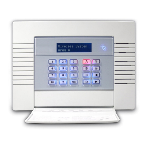
Pyronix Enforcer 32-WE Programming And Installation Manual
Wireless alarm system
Hide thumbs
Also See for Enforcer 32-WE:
- Programming reference manual (52 pages) ,
- User manual (36 pages) ,
- Setup manual (32 pages)
Table of Contents
Advertisement
EN50131-1:2006+A1:2009
EN50131-3:2009
EN50131-6:2008
EN50131-5-3:2005+A1:2008
PD6662:2010
Security Grade 2
Environmental Class II
Software Version >9.13
Programming and Installation Manual
Wireless Alarm System
RINS1549-4
PIEZO WARNING
The Enforcer system contains a
100dBA siren, please be aware
of this after an activation
Page: 1
Advertisement
Chapters
Table of Contents

Related Manuals for Pyronix Enforcer 32-WE


Summary of Contents for Pyronix Enforcer 32-WE
- Page 1 EN50131-1:2006+A1:2009 EN50131-3:2009 EN50131-6:2008 EN50131-5-3:2005+A1:2008 PD6662:2010 Security Grade 2 Environmental Class II Software Version >9.13 Programming and Installation Manual Wireless Alarm System RINS1549-4 PIEZO WARNING The Enforcer system contains a 100dBA siren, please be aware of this after an activation Page: 1...
-
Page 2: Table Of Contents
Enforcer Programming Manual C O N T E N T S P A G E 1. Introduction ..........................4 1.1 System Overview ......................... 4 1.2 Number of Additional Devices ....................4 2. The Engineer Menu ........................5 2.1 Entering The Engineer Menu ....................5 2.2 Exiting The Engineer Menu .................... - Page 3 6. Installation Guide ........................35 6.1 Mains and Earth Wiring ....................... 35 6.2 Inside of the Enforcer 32-WE: Rear ..................36 6.3 Inside of the Enforcer 32-WE: Front ..................36 6.4 Connecting / Replacing the Control Panel Battery ..............37 6.5 Important Installation Notes ....................
-
Page 4: Introduction
1 . I n t r o d u c t i o n The Enforcer 32-WE is a wireless alarm system that has been designed to enable easy installation and minimal maintenance. The Enforcer 32-WE protects the property (domestic or commercial) with a multitude of unique features: •... -
Page 5: The Engineer Menu
2.1 Entering The Engineer Menu Access to the Engineer menu will be allowed if the Enforcer 32-WE is unset. If set, the Enforcer 32- WE must be unset first via a valid user code/tag/keyfob in order to gain access. If the 'Allow Engineer Menu' function in the Master Manager Menu is set as 'No', the message ‘Authorisation Required’... -
Page 6: General Information
10 seconds after the key is released. 3.4 Keypads / Readers 3.4.1 The Enforcer Keypad and additional keypads (EUR-068) 3 additional wired keypads may also be connected to the Enforcer 32-WE. Refer to page: 39 for installation details. Enforcer... -
Page 7: Text Programming
The Enforcer 32-WE incorporates predictive text, so the system will predict the word that is being spelt. For example, if ‘B’ is pressed, and then and ‘e’ is pressed, Bedroom will be displayed, to accept this press . -
Page 8: Set / Unset System
3.7 Forced Arm On Inputs The 'Force Arm On Inputs' function enables two nominated inputs on the Enforcer 32-WE to be set. Either input can be triggered to allow real life signalling or alarm testing. This function is useful when a building is full of people and these tests are needed. -
Page 9: The Engineer Menu
NOTE: The HUB software version is labelled on the PCB. 4.2 Choose Mode If an Enforcer 32-WE I/O board or any Zone Expander Module (Input Expanders: ZEMs) are used, the resistance, EOL mode and response time of the inputs can be programmed. -
Page 10: Install Zems
Enforcer Programming Manual 4.3 Install ZEMs The Enforcer 32-WE supports up to 66 inputs. This is mapped by 32 wireless inputs and 34 wired inputs. 4.3.1 ZEM Address [0] ZEM Address 0 (Inputs 35-42) [1] ZEM Address 1 (Inputs 43-50) - Page 11 3. 'Learn Devices' will be displayed. Press . Control Inputs? 4. Press [ or ] to select the input (1-32) to learn and press . 5. Open the Enforcer 32-WE wireless device and press and hold the 'LEARN' button until all LEDs flash Learn Devices?
- Page 12 4. 'Learn Devices' will be displayed. Press . 5. Press [ or ] to select the bell (1 or 2) to learn and press . Control Bells? 6. Open the Enforcer 32-WE wireless Deltabell and press and hold the 'LEARN' button until all LEDs flash Learn Devices?
-
Page 13: Change Inputs
Select Button Lock 4.5 Change Inputs A total of 66 inputs can be programmed on the Enforcer 32-WE system. All inputs are unused by default. To save any programming the Engineer menu must be exited. 4.5.1 Input Types See Appendix B, page 49 for all input type options. -
Page 14: Assign Keypads/Readers
4.6 Assign Keypads/Readers Any additional keypads or readers must be addressed correctly before enabling them in this function. The Enforcer 32-WE keypad is automatically addressed as 0 on initial power up. Refer to page: 39 for more information. 4.6.1 Address Up to 3 x additional keypads or readers may be installed. - Page 15 programmed as this type. The lock open time and door open time can be programmed (in seconds). [3] Unset Only: If the Reader is to be used as an unset device only, select this type. [4] Entry Control: Used to lock/unlock doors. The external or internal reader can have magnetic locks connected to them.
-
Page 16: System Displays
Enforcer Programming Manual Programming Readers for Entry Control or Access Control: ASSIGN KEYPADS/ Assign Keypads/Readers READERS? 1. Press or to scroll to 'ASSIGN KEYPADS/READERS'. Press . Address 2. Press [ or ] to select the address. Press . 3. 'Type' will be displayed. Press 1 to select the reader.Press 4. -
Page 17: Change Timers
NOTE: This is NOT suitable for systems installed to comply with BS8243. [3] Push to Set (PTS): The Enforcer 32-WE system will only Set when a ‘Push to Set’ button has been pressed. This function will override the programmed Exit Time. -
Page 18: Change Codes
4.11.2 Change Duress Codes [2] Duress Code: If the Enforcer 32-WE is unset using a 'Duress' code, a silent 'Duress' or 'Hold Up' signal is sent. NOTE: ACPO policy prevents use of Duress codes for police call purposes. -
Page 19: Volume Control
4.12 Volume Control The Volume Control function applies to the loudspeaker output only. Volume levels at the keypad are programmed individually – refer to page: 14 on how to access the menu. 4.12.1 Volume Controls The following volume on each sound can be controlled: Entry, Exit, Alarm, Fire, Tamper, Day alarm, Chime, and Intelligent Set. -
Page 20: Change Outputs
'Confirmed Alarm'. The Enforcer 32-WE can operate on a combined Area basis, for example if both Areas ‘A’ and ‘B’ are set; you may want the process of the alarm responses to change. Therefore The ‘If Areas set’... -
Page 21: Intelligent Set
A and B assigned), but if a final exit input is activated (such as a front door) on level set A, the Enforcer 32-WE will automatically switch to setting level set A, If no input is activated, the Enforcer 32-WE will just set level set B. - Page 22 32-WE will display a wireless polling fault but will allow the user to set the system. If 'NO' the user will not be able to set the Enforcer 32-WE with a polling fault. The Enforcer 32- WE will display a fault and the arming procedure will be stopped.
-
Page 23: Engineer Reset Options
'Secure Intruder' should not be used. 4.17.2 Engineer Restore of Hold Up If 'YES', an Engineer code must be used to reset the Enforcer 32-WE after an Hold Up, Input Hold Up, or Duress activation. 4.17.3 Engineer Restore of Tamper If 'YES', an Engineer code must be used to reset the Enforcer 32-WE after a tamper activation. -
Page 24: Engineer Tests
Chime, Chime Follow, Exit, Exit Fault, Entry, Tech Fault, Tamper, Alarm, PA, and Fire. 4.19.2 Walk Test The walk test feature is used to test all the inputs programmed on the Enforcer 32-WE. It is recommended that after programming any inputs, the Engineer menu is exited to save all data, after this point a walk test should be performed. - Page 25 into Engineer Mode. If the test is aborted, it will NOT be performed until the next day. This is selected in SITE OPTIONS under “Do Battery Load Test”. The test may also be performed as required, under engineer control. 4.19.6 Test Outputs The engineer can test all the Programmable Outputs on the Input/Outboard board and the output module.
-
Page 26: Diagnostics
4.20.2 View Inputs This function shows all the input statuses on the Enforcer 32-WE (including Wireless and any expanders connected). The resistances can be shown, or just the status; C = Closed, O = Open, T = Tamper, - = Not learnt and F = Resistance fault. For wireless inputs; S = Supervision fault. - Page 27 Signal Strength One of the most important factors for a reliable wireless installation is the signal strength between a wireless device and the Enforcer 32-WE. If a device is out of range it will not be able to send events.
-
Page 28: Set Up Downloading
When this section refers to 'dials the software', this means the PC that the software is installed. 4.21.1 Download By A download from the Enforcer 32-WE to the PC can be done either by RS232 (direct connection - see page: 38) or Modem (remote dial in connection - see page 38). - Page 29 PC be called. Once answered, both the Enforcer 32-WE and the software will hang up. After a few seconds the Enforcer 32-WE will call the software and connect. 4.21.3 Telecom Line [0] Dedicated Line: When the software dials the Enforcer 32-WE, it will answer immediately.
-
Page 30: Program Arc / Sms
UDL Password 4.22 Program ARC / SMS? A PSTN modem (Digi 1200) or GSM modem (Digi-GSM) can be connected to the Enforcer 32-WE. The PSTN will signal Fast Format or SMS, and the GSM will signal SMS only. 4.22.1 Program ARC/SMS Calls Enabling the ARC/SMS will trigger the Enforcer 32-WE to look for a modem. -
Page 31: Way Calling
(CHC) number. To have this access please contact customer support. 4.22.4 Prefix Number The prefix telephone number is an extra digit required to reach the Enforcer 32-WE if needed, For example, dial 9 to get an ‘outside’ line. 4.22.5 3 Way Calling For future use. -
Page 32: Dial Out Menu
Data from PC, Data to PC, Diagnostics and Commissions. 4.23.1 Select PC to dial In the Enforcer 32-WE function 'Set Up Downloading', the PC number of where the UDL software is installed is programmed. To dial this number, so the Enforcer 32-WE connects to the software, use this function. -
Page 33: Clean Start
Enforcer 32-WE. 4.24.3 Clear Logs If this function is not accepted, then all event logs will be still present on the Enforcer 32-WE. NOTE: If everything is defaulted, the system memory will also be restored to factory defaults except the following: ... -
Page 34: Specification And Warranty
This product is sold subject to our standard warranty against defects in workmanship for a period of two years. In the interest of continuing improvement of quality, customer care and design, Pyronix Ltd reserve the right to amend specifications without giving prior notice. -
Page 35: Installation Guide
NOTE 1: Do not locate the mains cables next to internal cabling. NOTE 2: Ensure that the Enforcer 32-WE is not mounted on any metal surfaces. NOTE 3: That the mains cables should not be internally 'looped' as shown. This may interfere with the wireless antenna's. -
Page 36: Inside Of The Enforcer 32-We: Rear
4. The rear tamper adjustment screw is used if the tamper from the front of the Enforcer 32-WE isn't sitting flush to the back plate - this may happen if the Enforcer 32-WE is installed on an uneven surface. -
Page 37: Connecting / Replacing The Control Panel Battery
Ensure that the Input and Output Board (I/O Board) used to connect wired keypads, readers, inputs and outputs to the Enforcer 32-WE, and is only connected to circuits operating at SELV voltage. ... -
Page 38: Rs232 Connection / Uploading And Downloading Software
Enforcer Programming Manual 6.6 RS232 Connection / Uploading and Downloading Software The Enforcer PC software (InSite) can be downloaded from http://www.pyronix.com/pyronix- downloads.php. To enable the Enforcer to receive upload/download commands, refer to page: 28. 6.6.1 Serial Connection (RS232) 1. Open up InSite. -
Page 39: Input / Output Board
6.8 Connecting Peripherals to the I/O Board 6.8.1 Connecting Keypads (EUR-064) Up to 3 additional keypads can be connected to the Enforcer 32-WE. These will be addressed individually and also addressed in the Engineer function '‘Assign Keypads / Readers’. Addressing at the keypad Each keypad will also need to be addressed individually, press and hold the D key until ‘SECURITY CODE’... - Page 40 Enforcer Programming Manual 6.8.2 Connecting Internal Tag Readers (EUR-107) Up to 3 readers can be connected to the Enforcer 32-WE. Each keypad are reader needs to be addressed as described below. These will also need assigning in the Engineer function '‘Assign Keypads / Readers’.
- Page 41 The resistor value will correspond to the value selected in ‘WIRING CHOICE’. IMPORTANT: THE BELL BOX CONNECTED WILL NEED TO BE IN SCB MODE. Unless the bell box is a Pyronix Deltabell. 6.8.5 Wiring Wired Inputs The End of Line value for all wired inputs is programmed in ‘PROGRAM EOL. At default they are set to DEOL and the resistor values are 4K7 for Alarm and 2k2 for tamper.
-
Page 42: Connecting An Input Expander
ZEM Address 2 (Inputs 51-58), ZEM Address 3 (Inputs 59-66). 6.10 Connecting an Output Expander 1 x Remote Output Expander can be connected to the Enforcer 32-WE. Each output expander allows 16 additional outputs. NOTE: The above shows the I/O board connected to a EURO-OEM8R8T. If using a EURO- OEM16R+PSU, the D2+ MUST NOT be connected. -
Page 43: Pstn Modem
IMPORTANT NOTE: TURN OFF THE MAINS BEFORE DISCONNECTING THE PSTN MODEM The PSTN modem card is used to enable the Enforcer 32-WE to communicate either via contact ID, Fast Format, SIA or SMS texts via a telephone line. It will also enable remote uploading/downloading. - Page 44 Enforcer Programming Manual 6.12.3 Digi GSM connection NOTE: The product has been approved as supplied. If the communications module is replaced with a different model, then the certification will be void. Page: 44...
-
Page 45: Appendix A. Defaults
Area A Text Full Set Area B Text Night Set Area C Text Area C Area D Text Area D Sign on Message Enforcer 32-WE Site Name Display When Set No [0] Display Alarms No [0] Display Hus No [0] Display Inputs... -
Page 46: Abcd
Enforcer Programming Manual Clean Start 2000 Clean Start 2020 Engineer Menu’s (Ungraded) (PD6662 EN Grade 2) A, B, C, D: Siren Time [04] Confirm Time [30] HU Confirm Time [08] Strobe Time [00] Re-Arm No AC Signal Delay [040] Settle [005] Double Knock [10]... - Page 47 Clean Start 2000 Clean Start 2020 Engineer Menu’s (Ungraded) (PD6662 EN Grade 2) Fire, Gas, HU Start At Digi [3] Fire Stops At Digi [3] HU Stops at Confirm [4] Day Alarm Starts Sirens Only [2] Day Alarm Stops Sirens Only [2] CHANGE OUTPUTS Endstation Outputs BELL O/P...
- Page 48 Enforcer Programming Manual Clean Start 2000 Clean Start 2020 Engineer Menu’s (Ungraded) (PD6662 EN Grade 2) Program ARC/SMS Calls ARC/SMS is Disabled [1] Active No [0] Format SMS Message [133] (PSTN ONLY) 1st ARC/SMSC 07785499993 Mobile Number Valid Areas ABCD Content 1-16 Content 17-32 Redials...
-
Page 49: Input Types
A p p e n d i x B . I n p u t T y p e s Number & Type Operation Unused Factory default. Input is programmed out of operation. Active at all times. Audible response: Full (differentiated). Fire Communicator: ‘Fire’... -
Page 50: Appendix C. Timers
Enforcer Programming Manual A p p e n d i x C . T i m e r s Timer Function Range Entry Time Entry time for each area. (if programmed as the input type ‘Final Exit’) 0 – 255 seconds Exit Time Exit time for each area. -
Page 51: Appendix D. Output Types
A p p e n d i x D . O u t p u t T y p e s Type Active Restore 0000 Not Used (permanently off) 0001 Fire At alarm When a valid code is entered At a HU or Duress alarm 0002 Hold Up Any When a valid code is entered... - Page 52 Enforcer Programming Manual Type Active Restore 20 seconds after set/unset 0034 Lights When exit or entry timer starts procedure completed 0035 Follow Input When input triggers Dependent upon programming 0037 Restore 1 At code entry to set After 3 seconds At code entry to set When unset 0038...
-
Page 53: Tamper Any
When input is 1xxx Follow input xxx When input clears activated Default Digi Channels Digi Channel Enforcer 32-WE Fire (0001) HU Device Any (0009) Unconfirmed Any (0018) Final Set Any (0022) Tamper Any (0007) Omit Rearm Any (0017) Confirmed Any (0006) -
Page 54: Appendix E. Content Types
Enforcer Programming Manual A p p e n d i x E . C o n t e n t T y p e s Description Final Set, System Rearm, ATM set, Secure set system System set by auto set, Auto set cancelled by user, Forced Set, System unset by auto unset ATM disarmed Access Exit Request, Special Unset Set Fail, Set Fail (with zone) -
Page 55: Fault Codes
A p p e n d i x F . F a u l t C o d e s If a device on the Enforcer 32-WE is not installed correctly or has lost its communication with the panel, “DEVICE FAIL” will be shown on the keypad as shown: Co nt ro l Pan el Mai n pa ne l fau lt (e .g . -
Page 56: Mains Fail
Enforcer Programming Manual Fault Indications RS-485 BUS PROBLEMS Fault Description Solution 485 Fail xxx Device on RS-485 Identify device from the location/name and the device communications bus is type. Check device addressed correctly to match failing to communicate programming. Ensure that 2 devices of the same type correctly with the control do not share the same address. - Page 57 DETECTION FAULTS Fault Description Solution Case Tamper Case tamper switch open Secure switch closed. Same method of showing the device as battery fault. COMMUNICATION FAULTS Fault Description Solution Control End Station unable to If modem not present, ensure that “Disable Digi” option Panel communicate with Digi is set to ‘YES’...
- Page 58 Enforcer Programming Manual Page: 58...
- Page 60 Secure Holdings Pyronix House Braithwell Way Hellaby Rotherham S66 8QY Customer Support line (UK Only): +44(0)845 6434 999 (local rate) or +44(0)1709 535225 Hours: 8:00am - 6:30pm, Monday to Friday Email: customer.support@pyronix.com Website: www.pyronix.com...
Need help?
Do you have a question about the Enforcer 32-WE and is the answer not in the manual?
Questions and answers