
Related Manuals for Pyronix EURO 46 V10


Summary of Contents for Pyronix EURO 46 V10
- Page 1 EURO 46 V10 Installation Manual PD6662:2010+IA501:2015 EN50131-1:2008+A1:2009 EN50131-3:2009 Security Grade (SG) 3 - Large Security Grade (SG) 2 - Small Environmental Class (EC) II Software Version >10 RINS1941-2...
- Page 2 EURO 46 V10 Installation Manual...
-
Page 3: Table Of Contents
Access Levels Compliance Warranty Additional Device Manuals Wired Setting Devices Wireless Setting Devices Zone Expansion Modules Output Expansion Modules External Wired Sounders Customer Support Pyronix Training Academy Online Pyronix Training Academy Training Videos Technical Support EURO 46 V10 Installation Manual... -
Page 4: System Overview
110 x 170 x 40 mm (H x W x D) Large Case 390 x 305 x 100 mm EN grading 2 (small metal) 3 (large metal) Environmental class Default Codes Engineer - 1111 Master Manager - 2222 EURO 46 V10 Installation Manual... -
Page 5: Input Mapping
75-76 TOTAL PLEASE NOTE: 2 x EURO-ZEM32-WE can be connected to the EURO 46 V10. Each expander allows 32 inputs which are separated into 4 addresses (each address enables 8 wireless inputs). It is possible to mix the wired and wireless remote expanders. -
Page 6: Output Mapping
Output Mapping Devices Address Outputs Numbers EURO 46 V10 APP PCB 5 (2 shared) Digi/ATE Outputs (using communication loom) EURO-OEM8R8T / EURO-OEM16R+PSU 1-16 EURO-OEM8R8T / EURO-OEM16R+PSU 17-32 EURO-ZEM8+/ EURO-ZEM8+PSU EURO-ZEM8+/ EURO-ZEM8+PSU EURO-ZEM8+/ EURO-ZEM8+PSU EURO-ZEM8+/ EURO-ZEM8+PSU EURO-ZEM8+/ EURO-ZEM8+PSU EURO-ZEM8+/ EURO-ZEM8+PSU EURO-ZEM8+/ EURO-ZEM8+PSU... -
Page 7: Technical Specification
SD Voltage which the deep discharge protection function will operate at: 10V Over Voltage Protection Trigger Voltage: 18V Battery Charging Specification Float voltage 13.8VDC Recharge time <24 hours 300mA (3A to 6A) Standby battery capacity Battery low voltage cut off 10.5V current 700mA (7A to 17A) EURO 46 V10 Installation Manual... - Page 8 PLEASE NOTE: EURO 46 V10 power supplies are NOT designed for use with multiple batteries connected. System load should not exceed the panel power supply output shown above, or the maximum load supportable by the battery for the specified backup time, as in the table shown below.
-
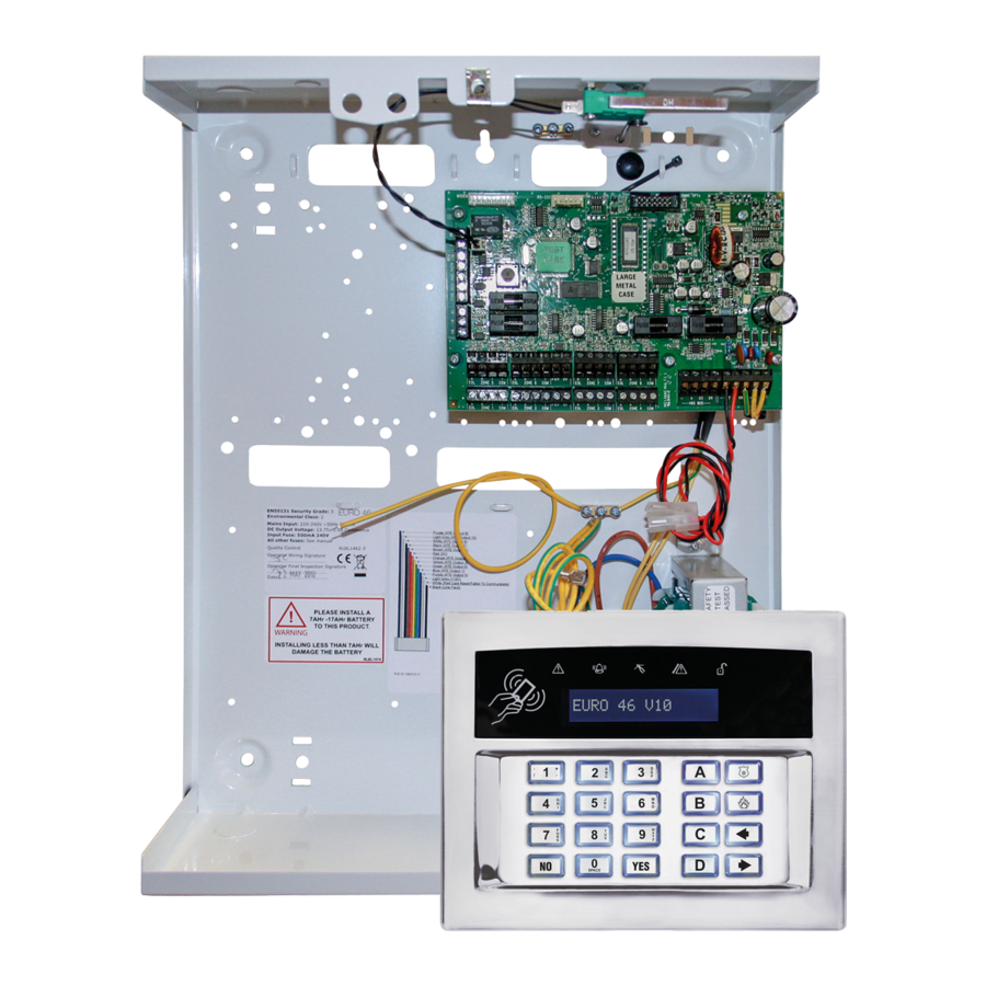
Page 9: Out Of The Box
Unscrew and remove the cover of the EURO 46 V10 (Figure Figure 1 1). The EURO 46 V10 printed circuit board is located to the top right hand side. (Figure 2) Install the supplied stand-offs if needed before mounting the metal case to the wall (Figure 3). -
Page 10: The Printed Circuit Board
10: RS485 bus terminals communicator to the panel. Connects peripherals. 18: Bell Fuse 11: Battery connection 19: Auxiliary Fuse For battery back up. 20: Bus Fuse 12: Earth connection 21: Battery Fuse Connects the earth. EURO 46 V10 Installation Manual... -
Page 11: Communication Loom
‘Invert ATE O/Ps’ and can be found as a sub menu in ‘SYSTEM OPTIONS’ then ‘Site Options’. This will invert the polarity of all the programmable ATE outputs, they cannot be done individually. EURO 46 V10 Installation Manual... -
Page 12: Power And Battery Connections
PLEASE NOTE: Ensure that the ‘battery jumper’ is in the correct position for the capacity of battery that you have connected – otherwise the panel may under-charge a large battery or over-charge and damage a smaller battery. EURO 46 V10 Installation Manual... -
Page 13: 485 Bus Wiring
NOTE 4: There must be a ferrite bead fitted to one of the outgoing data lines and secured inside the EURO 46 V10 case itself. The Ferrite bead is supplied packaged with a cable-tie which must be used to secure it in the case and prevent it shorting any electrical contacts (Ferrite as shown). -
Page 14: Star And Daisy Chain Wiring
Use this type of cable 6 core alarm cable when the wiring of the (doubling D1 (0v) and 485 bus is located near 1000 50 m 1 km D2 (+12V)) 230VAC mains power wiring Twisted Pair 1000 EURO 46 V10 Installation Manual... -
Page 15: Input Connections
This is added on to the end of the alarm tolerance in order to create a wider alarm tolerance range. EURO 46 V10 panels are set to 4k7/2k2 at default and would typically used a 2k2 resistor for tamper, 4k7 resistor for alarm and finally a 6k8 resistor for mask. -
Page 16: Output (Pgm) Connections
If Inputs 7 and 8 are programmed as ‘unused’, these inputs can be used as 2 further outputs (known as XPGM1 and XPGM2). Which are programmed in ‘CHANGE OUTPUTS’ in the Engineer Menu. Normal State: 12V Active State: 0V Current: 50mA switched to 0V EURO 46 V10 Installation Manual... -
Page 17: External Sounder Connections
External Sounder Connections Grade 3 Wiring FOR FUTURE Grade 2 Wiring FOR FUTURE EURO 46 V10 Installation Manual... -
Page 18: Modems
For programming instructions please refer to the ‘Communications Guide’. UDL Software The EURO 46 V10 control panel can be programmed by the LCD menu or the UDL InSite Software, provided free of charge. It can be downloaded from https://www.pyronix.co.uk/help-and-support/ installers-distributors/insite-software-download/insite-software-download. The connection between... -
Page 19: Connecting Insite To The Panel Via Rs232
Now on the ‘Site Name’ screen, this is compulsory, make sure that you take a note of it for use later in the Insite software then press . Now on the ‘UDL Priority’ screen – we recommend setting this to ‘High [0]’. PLEASE NOTE: This prevents HomeContol+ App events / notifications from disconnecting the UDL connection. EURO 46 V10 Installation Manual... -
Page 20: Connecting Insite To The Panel Via The Cloud
Click ‘Dial’. If connection is successful, the Cloud Icon will become blue, and a dialogue box will appear asking if you would like to create a customer – click ‘Yes’ to continue. The EURO 46 V10 control panel is now successfully connected to the Insite UDL software. EN 50131 Terminology... -
Page 21: Access Levels
key. Compliance As per EN 50131-1 the EURO 46 V10 is capable of supporting all conditions A,B and C: - In Grades 1 & 2 I&HAS when an I&HAS or part thereof is in a set state: A) access to the supervised premises or part thereof, via an entry/exit route, shall be prevented, or B) opening the door to the entry/exit route shall initiate an entry procedure, or C) indication of the set/unset status shall be provided. -
Page 22: Additional Device Manuals
Please scan the relevant QR code below to download the manual on a specific product. In order to download any of our manuals you will be required to sign up to the website. This can be done simply by going to www.pyronix.co.uk/register or scanning the QR code to the right. -
Page 23: Customer Support
Email your full contact details and company name to videot@pyronix.com now and you can watch, learn and install whenever you want. You will receive an email confirmation once your application has been approved.
Need help?
Do you have a question about the EURO 46 V10 and is the answer not in the manual?
Questions and answers