Pyronix Enforcer 32WE Setup Manual
Hide thumbs
Also See for Enforcer 32WE:
- Programming and installation manual (60 pages) ,
- Programming reference manual (52 pages) ,
- User manual (36 pages)

Related Manuals for Pyronix Enforcer 32WE


Summary of Contents for Pyronix Enforcer 32WE
- Page 1 Wireless Setup Guide EN50131-3 : 2009 EN50131-6 : 2008 EN50131-5-3 : 2005 Security Grade 2 Environmental Class II RINS1348-3...
- Page 2 Default codes: User code:1234 Master Manager Code: 2222 Engineer Code: 1111...
-
Page 3: Table Of Contents
Contents Page The Enforcer Wireless Devices Simple Learning Guide Powering Up / Entering & Exiting Engineers Learning Contacts and Detectors Learning Bells Learning Keyfobs Deleting Inputs / Bells Diagnostics Wireless Functions Fault Displays MC1-WE KX12DQ-WE KF4-WE SHOCK-WE DELTABELL-WE... -
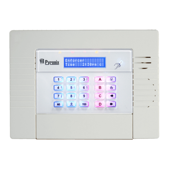
Page 4: The Enforcer
The Enforcer The Enforcer Control Panel SPACE a = Exit manager menu b = Moves backwards to the previous menu item c = Enables chime and displays additional information in the log d = Moves forward in the log, scrolls between options/enters the master manager menu/bypasses inputs f p = Not used [ ] = Directional buttons. -
Page 5: Wireless Devices
Wireless Devices Wireless Detectors Status LEDs ALARM PIR Sensitivity Learn Button High Please note: that if learning smoke/carbon sensors only a learn button and 1 LED will be present. Wireless Contacts Status LEDs ALARM Enable contact 1 Disable contact 1 Learn Button Learn Button... -
Page 6: Simple Learning Guide
Simple Learning Guide Learning Inputs (In Engineer’s Mode) Use b and x to scroll to: RADIO DEVICE CONTROL? Control Inputs? Learn Devices? Press t Input 01 Learning... Available [01] Press t Press t Enter Input. Press t Learning Bells (In Engineer’s Mode) Use b and x to scroll to: RADIO DEVICE CONTROL? - Page 7 The input types will then Input Learnt need to be programmed. Please see ‘Change Inputs’ Input learnt in the programming manual. successfully Press the ‘LEARN’ button on the detector/ contact until the LEDs cycle, then release. Please note: that if learning smoke/carbon sensors only a learn button and 1 LED will be present.
-
Page 8: Powering Up / Entering & Exiting Engineers
Powering Up / Entering & Exiting Engineers Please note that the initial power up may take a Please Wait... few minutes. Once the time is displayed, programming can Enforcer begin. Time 03:21c Day Mode Entering the Engineer Menu Exiting the Engineer Menu SOFTWARE Enforcer REVISION? -
Page 9: Learning Contacts And Detectors
Learning Contacts & Detectors It is recommended that all detectors, door contacts or Use b and x to scroll to: smoke detectors are learnt at the Enforcer before any installation/mounting is done. This makes learning RADIO DEVICE much quicker. CONTROL? ... -
Page 10: Learning Bells
Learning Bells Use b and x to scroll to: It is recommended that all wireless bells are learnt at the Enforcer before any installation/mounting is done. RADIO DEVICE This makes learning much quicker. CONTROL? Press t Control Inputs? Press x ... -
Page 11: Learning Keyfobs
Learning Keyfobs Day mode The master manager menu has to be used to assign keyfobs to the user codes. Follow the Enforcer instructions to the right to enter the master manager Time 8:30am c menu (for more information please see the user manual). -
Page 12: Deleting Inputs / Bells
Deleting Inputs / Bells Deleting inputs and bells from the Enforcer can either be done collectively or individually. Deleting Inputs Deleting Bells Use b and x to scroll to: Use b and x to scroll to: RADIO DEVICE RADIO DEVICE CONTROL? CONTROL? Press t... -
Page 13: Diagnostics
Diagnostics Use b and x to scroll to: The diagnostics function shows all wireless (radio) input and bell signal strengths and battery strengths. DIAGNOSTICS? Signal Strength (Inputs and Bells) One of the most important factors for a reliable Press t wireless installation is the signal strength between a wireless device and the panel. - Page 14 Diagnostics Diagnostics Continued... Battery Status The diagnostics function also monitors the battery of Bell No Signal [000] each of input and bell so that any low/bad batteries can be quickly recognised and replaced. Press t The Enforcer has an advanced battery test mechanism Battery? that operates by monitoring all inputs/bells after 5 minutes from the start of the test.
-
Page 15: Wireless Functions
Wireless Functions Site Options Use b and x to scroll to: In the site options function there are 3 functions for the SITE OPTIONS? Enforcer: • Radio Force Set: If any radio device is in fault Press t until: (e.g. has failed supervision or the signal is jammed) and if this option is enabled, the user can Radio Force Set force the Enforcer to set regardless. -
Page 16: Fault Displays
Fault Displays Radio Mismatch: If an input is assigned as a type (final exit, intruder, etc) but a detector has not been learnt on this input Radio mismatch Input 01 number or a detector has been learnt but not assigned an input type, this fault will be displayed. -
Page 17: Mc1-We
CR2 Battery installed MC1-WE Wireless magnetic contact/universal transmitter with 1 reed, 1 input & tamper Technical Specifications Model: MC1-WE Colour: WHITE Casing: 3mm ABS, 0.4mm HDPE in Lens Area Transmission Frequency: 868MHz, FM Transceiver Narrow Band Transmission Method: Fully Encrypted Rolling Code Transmission Range: 300m Free Space Three LED Combinations... - Page 18 MC1-WE Wireless magnetic contact/universal transmitter with 1 reed, 1 input & tamper Back view of the MC1-WE Tamper Switch Detection point Using Magnetic Contact 1 on a window Magnet ng Magnetic Contact 1 (S1) WINDOW To enable Magnetic Contact 1 you must remove the jumper link from the S1 enable pins: Frame Reed Switch...
- Page 19 Magnetic Contact 1 Universal Transmitter Tamper Zone ZONE Learn Enable/ Enable/ Enable/ Magnet Example: Disable Disable WINDOW Disable MC1-WE Door Wireless magnetic contact/universal transmitter Contact with 1 reed, 1 input & tamper Learn Contact / Sensor Butto S1 Enable Applying the battery TAMPER Test Result Universal Transmitter...
-
Page 20: Kx12Dq-We
CASE LID CR123A SCREW FITTING LITHIUM mponents, BATTERY eds to be 2m 3m 5m 6m 8m 9m ide of the KX12DQ-WE 12m Wireless PIR Detector touching onductor Part number: FPKXBRACKET ediately Wall Ceiling 2.4m Technical Specifications Header for Rear Tamper 2m 3m 5m 6m 8m 9m... - Page 21 KX12DQ-WE 12m Wireless PIR Detector Wall Ceiling Installation & wall mounting ng the it is NOTE: When mounting the CASE LID detector, ensure that it is SCREW FITTING not tilting backwards. Part number: FPKXBRACKET Optional bracket fitting Header for Rear Tamper Wall Ceiling (0.12")
-
Page 22: Avoiding False Alarms
KX12DQ-WE 12m Wireless PIR Detector DIGITAL SIGNAL PROCESSING SELECT Learn Button Avoiding false alarms SENSITIVITY Header On = HIGH) 1. Avoid placing the detector in direct sunlight. 2. Do not let pets and other animals wander freely whilst the alarm system is armed. Piro Sensor Header Off 3. -
Page 23: Kf4-We
KF4-WE 4 Button, two way Specifications Transmission Frequency: 868MHz Transmission Method: Fully encrypted rolling code Transmission Range: 300m free space Battery: CR-1/3N Li-Mn Cell (3 volts) Battery Life: Up to 2 years Operating Temperature: -10 to +40 °C Emissions: EN55022 Class B Immunity: EN50130-4 Dimensions:... - Page 24 KF4-WE 4 Button, two way II Button Changing The Battery The batteries supplied have been chosen to provide long service life whilst, for safety reasons, having limited output current. Replace only with approved batteries. (Negative) To prevent possible damage to components, any static charge on your body needs to be (Positive) eliminated before touching the inside of the...
-
Page 25: Shock-We
Battery SHOCK-WE LEDs Wireless transmitter with wall tamper and shock sensor The wireless transmitter with wall tamper and shock sensor is used on the Enforcer Radio Control Panel along with the current range of detectors, receivers and transmitters. The function of the shock sensor wireless transmitter is to provide an alarm signal if vibrations picked up from its mounting surface exceed a predetermined level, which can be easily adjusted. - Page 26 Sensitivity High range sensitivity band SHOCK-WE Low range sensitivity band Wireless transmitter with wall tamper and shock sensor Disturbance: Rolling 30s period Sensitivity Descriptions High range sensitivity band Operating Environment Electrical Specification Sensitivity Low range sensitivity band 1. Tri-Colour LED: When the sensor detects a vibration, the LED will illuminate in one of two colours: -10 to 50°C Voltage: >2.5V High range sensitivity band...
- Page 27 Test Result SHOCK-WE S1 Enable Wireless transmitter with wall tamper and shock sensor TAMPER Learning the SHOCKWE to the Enforcer control panel Universal Transmitter ZONE Learn Example: When you are ready to learn the device to the control panel receiving equipment, and when the equipment is in the learn mode (see Enforcer Programming Manual) follow the procedure below.
-
Page 28: Deltabell-We
DELTABELL-WE External sounder Technical specification Battery CR3 3.0 volt 11000MAh Lithium battery Strobe duration 10mS Strobe Frequency Sound pressure level 101dBA Dimensions 290 x 285 x 50 mm Reverse polarity protected Installation Steps: Step 1 Slide the PCB module upwards. The sprung back-tamper arm can be retracted to allow removal. - Page 29 Tampe levellin screw DELTABELL-WE External sounder Step 4 Place the PCB module, ensuring that the arrow is aligned with the marker (on the left of the module). Expose the terminals by releasing the latch on the top of the PCB module. Tamper levelling screw...
- Page 30 DELTABELL-WE External sounder Battery Using Magnetic Contact 1 (S1) To enable Magnetic Contact 1 you must remove jumper link from the S1 enable pins: Battery Door Frame Reed Switch Door Test Result S1 Enable The batteries supplied have been Back view of the MC1-WE chosen to provide long service life whilst, for safety reasons, having limited output current.
- Page 32 Customer support: Customer support line (UK only): +44(0)845 6434 999 (local rate) Or telephone: +44(0)1709 535225 Hours: Mon to Fri, 8:00am till 6:30pm Email: customer.support@pyronix.com Website: www.pyronix.com Email: support@castle-caretech.com Website: www.castle-caretech.com...
Need help?
Do you have a question about the Enforcer 32WE and is the answer not in the manual?
Questions and answers