Table of Contents
Advertisement
Advertisement
Table of Contents

Related Manuals for Sartorius Combics Series


Summary of Contents for Sartorius Combics Series
- Page 1 Presented By Dallas Ft Worth Austin Houston NicolScales.com 800.225.8181 Contact Us Nicol Scales & Measurement is an ISO Accredited Calibration Company that has provided calibration, repair and sales of all types of weighing and measurement products since 1931.
-
Page 2: Connect Weighing Platforms: Combics
Operating Instructions Sartorius Combics Series Indicator Models CAISL1, CAISL2, CAIS1, CAIS2 98648-018-24 98648-018-24... -
Page 3: Table Of Contents
Entering Adjustment and Linearization Weights Repairs Function Allocation of the J Key Cleaning External Linearization Safety Inspection Setting the Preload Disposal Clearing the Preload Specifications Device Dimensions Adjustment Without Weights Operating Design Accessories Turning on the Device Documents List Sartorius Services Menu Operating Design Declarations of Conformity Configuration Setting up Password Protection EC Type-Approval Certificate Operation Test Certificate Weighing Plates and Markings Menu Structure Calibration, Adjustment Index SQmin Function Appendix: Data ID Codes Guide to Verification of Weighing Instruments... -
Page 4: Notes On Using This Manual
Notes on Using this Manual Notes on Using this Manual t P lease read this entire manual carefully and completely before using the device. t Read the safety precautions carefully. t T his manual is part of the product. Keep it in a safe and easily accessible location. t I f the manual should be lost or misplaced, please contact Sartorius for a replacement or download the latest manual from our website: www.sartorius. Symbols and Signs The following symbols are used in this manual: Warning symbol for various types of dangers. These symbols are explained in more detail in Section “Safety Instructions." This symbol indicates useful information and tips. Dieses Symbol kennzeichnet Hinweise für den eichpflichtigen Verkehr im Gültigkeitsbereich der EG-Richtlinie 2009/23/EG. , This and similar symbols mean that the respective key should be pressed. T T ... -
Page 5: Warnings And Safety Precautions
Warnings and Safety Precautions Warnings and Safety Precautions Combics indicators comply with the European Council Directives as well as international regulations and standards for electrical equipment, electromagnetic compatibility, and the stipulated safety requirements. Improper use or handling can, however, result in damage and/or injury. t R ead these operating instructions carefully before use. This will prevent damage to the equipment. The protective conductor must not be disconnected for any reason. Use only stand- ard cables that have protective grounding conductors. If there is visible damage to the equipment or power cord: unplug the equipment and secure it against further use. Make absolutely sure to unplug the indicator from power before you connect or disconnect any electronic peripheral devices to or from the interface port. The device should only be opened by personnel trained in accordance with Sartorius guidelines. If you use electrical equipment in installations and under ambient conditions requiring higher safety standards, you must comply with the provisions as specified in the applicable regulations for installation in your country. The operator shall be responsible for any modifications to the equipment and for any connections of cables or equipment not supplied by Sartorius and must check and, if necessary, correct these modifications and connections. Information on operational quality is available upon request from Sartorius (in line with norms pertaining to immunity). Do not expose the equipment to aggressive chemical vapors or to unnecessarily extreme temperatures, moisture, shocks, or vibration. Only clean the device as stipulated in the cleaning instructions: Refer to the “Care and Maintenance" chapter. The display value can be affected by extreme electromagnetic influences. Once the disturbance has ceased, the instrument can be used again in accordance with its intended purpose. - Page 6 Installation Warning when using pre-wired RS-232 connecting cables: RS-232 cables purchased from other manufacturers often have pin assignments that are incompatible with Sartorius products. Be sure to check the pin assignments against the chart in this manual before connecting the cable, and disconnect any lines identified differently from those specified by Sartorius. Connect only Sartorius accessories and options, as these are optimally designed for use with your device. Therefore, do not use any proprietary solutions. The operator shall be solely responsible for installation and testing of any modifications to Sartorius equipment, including connection of cables or equipment not supplied by Sartorius. Information on operational quality (in line with norms pertaining to immunity) is available on request. t I f you have any problems with your device, contact your local Sartorius office, dealer or service center. IP Protection Rating IP Rating: – All models are rated to IP44 (IP65 as an accessory). – “IP65" models are rated to IP65. – T he IP65/IP69K protection rating is ensured only if the rubber gasket is installed and all connections are fastened securely (including the caps on unused sockets). Weighing platforms must be installed and tested by a certified technician. – I f you install an interface port or battery connection after setting up your indicator, keep the protective cap in a safe place for future use. The cap protects the interface connector from vapors, moisture and dust or dirt. Use in Legal Metrology – W hen the indicator is connected to a weighing platform and this equipment is...
-
Page 7: Device Description
Device Description Device Description Combics indicators: – Are robust and durable, thanks to their stainless steel housing – Are easy to clean and disinfect – Are easy to operate, thanks to the following features: – Large, backlit display elements (14 segments) – Large keys with positive click action – Can be operated independently of the weighing platform location – Have a range of interfaces for flexible use – Have optional password protection for operating parameters Combics 1 offers these practical functions: – Easy calibration via a separate key – Automatic tare for loading – Alibi memory connection option available – Internal rechargeable battery – Automatic printing for loading – Configurable printout – Flex print Combics 2 speeds up your routine procedures with: – Integrated programs for applications (some can be combined): – Counting – Neutral measurement – Averaging (animal weighing) – Weighing in percent... -
Page 8: General View Of The Equipment
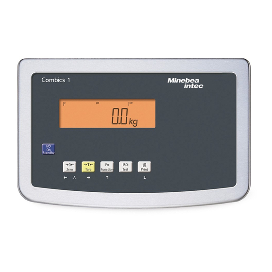
Device Description General View of the Equipment Combics 1 and 2 1 D isplay (for a detailed diagram, please see the chapter “Operating Design") 2 On/Off key 3 G eneral function keys: Zero, Tare, Switch function, Adjustment/Calibration, Print/Data output (see “Operating Design") Combics 2 only 4 1 0 digit keypad for entering values 5 L EDs (for checkweighing and classification) 6 A dditional function keys (see “Operating Design") 7 Toggle between weighing platforms (WP) Back CAIS1 | CAIS2 8 C onnection options for... -
Page 9: Installation
Installation Installation When a Combics indicator is ordered with special equipment, the desired options come pre-loaded from the factory. Storage and Shipping Conditions Once the equipment has been removed from the packaging, it may lose accuracy if subjected to strong vibration. – D o not expose the equipment to unnecessarily extreme temperatures, moisture, shocks, blows or vibration. – Permissible storage temperature: –10°C to +40°C Installation Location Avoid adverse influences at the place of installation: – E xtreme temperatures (operating temperature: –10°C to +40°C) – Aggressive chemical vapors – Extreme moisture (according to IP protection class) Unpacking t A fter unpacking the device, check it for any visible damage as a result of rough handling during shipment. y I f you detect any damage, proceed as directed in the chapter entitled “Care and Maintenance" under “Safety Inspection." t S ave the original packaging for any future transport. Unplug all connected cables before packing the equipment. -
Page 10: Getting Started
Getting Started Getting Started Steps 1.) C onnect weighing platform to the indicator. 2.) C onfigure the analog/digital converter (ADC): see page 19 3.) C arry out an alignment: for adjustment, see page 26, for linearization see page 27 4.) C onnect peripheral devices, e.g. printer to the COM1 or UNICOM interface: see Data Interfaces chapter starting on page 102 Connecting Weighing Platforms to WP1 An analog Sartorius platform (CAPP, CAPS, IU or IF) or a commercially-available DMS load cell can be connected to the Combics indicator WP1 input. The load cell should be connected by a certified technician who has received specialized training from Sartorius. Any installation work that does not conform to the instructions in this manual results in forfeiture of all claims under the manufacturer’s warranty. Peripheral devices should be connected by a certified technician who has received specialized training from Sartorius. Any installation work that does not conform to the instructions in this manual results in forfeiture of all claims under the manufacturer’s warranty. Disconnect the equipment from the power supply before starting connection work. t S et up the weighing platform (see Operating Instructions for the weighing plat-... - Page 11 Check the shielding and clamps. t S ecurely connect the wires of the connecting cable in accordance with the terminal assignments. t A fter you close the housing again, use a pressure gauge to check the integrity of the IP69K protection. For details, contact the Sartorius Service Center. Connecting Cables t I nsert all cable wires through the ferrite case, wind them around the ferrite case and then reinsert back through the ferrite case. t S crew the wires tightly into the clamps. See the following pages for terminal pin allocation t R efer to the data sheet or operating instructions of the weighing platform for details on the assignment of wire colors/signals. Ensure any lines that...
-
Page 12: Connecting Weighing Platforms: Combics 1
Getting Started Connecting Weighing Platforms: Combics 1 Interface PCB for ADC 2*3000e (option A8) Com 1 COM1 terminal assignments 1 LOAD_PRINTER 11 Clear to Send (CTS) 2 RESET_OUT 12 Data Terminal Ready (DTR) 6 3: G ND 13 Data Input (RXD) 4 GND 14 Data Output (TXD) 5 5V_OUT 15 GND 6 5V switched 16 Universal In 7 GND... - Page 13 Getting Started Connecting Weighing Platforms: Combics 2 Interface PCB for ADC 2*3000e (option A8) Com 1 COM1 terminal assignments (applies to all PCBs) PS/2 1 LOAD_PRINTER 11 Clear to Send (CTS) 21 5 V switched 2 RESET_OUT 12 Data Terminal Ready (DTR) 22 PS2_Data 3: GND 13 Data Input (RXD) 23 PS2_Timer 4 GND 14 Data Output (TXD)
-
Page 14: Pin Assignment Chart
Getting Started Pin Assignment Chart Models (IP44 protection) CAISL1 CAISL2 COM1 female connectors: 25-pin D-Submini female connector (DB25S) with screw lock hardware for cable gland Recommended interface connector: 25-pin D-Submini (DB25) with shielded cable clamp assembly and shield plate (Amp type 826 985-1C) and fastening screws (Amp type 164868-1) COM1 pin assignments Pin 1: Shield Pin 2: Data output (TxD) Pin 3: Data input (RxD) Pin 4: Pin 5: Clear to send (CTS) Pin 6: Not assigned Pin 7: Internal ground (GND) Pin 8: Internal ground (GND) Pin 9: Not assigned... - Page 15 Getting Started Cabling Diagram - Connection to a PC Use the following cables to connect a PC to the indicator in accordance with the RS-232C/V24 standard (max. cable length 15 m): Models CAISL1, CAISL2: connecting cable 7357312 Models CAIS1, CAIS2: connecting cable YCC02-D9F6 V24 Cable Diagrams Connection assignments for the cable from the indicator to an RS-232 PC interface (COM1). Indicator side PC side Models CAISL1, CAISL2 DSUB connector 25-pin D-Sub male connector 9-pin or 25 pin Sgn GND 5 GND 7 GND TxD 2 RxD 3 RxD RxD 3 TxD 2 TxD DTR 8 CTS...
- Page 16 Re-attach the front panel and secure it with the ten cap nuts. Connecting the Device to AC Power The device is powered through the installed power cord. The power supply is integrated into the indicator. The device can be operated with a voltage of 100 V to 240 V. The power connection must be made in accordance with the regulations applicable in your country. The printed voltage rating (see type label) must match the voltage in the place of installation. If the voltage specified on the label or the plug design of the AC adapter do not match the rating or standard you use, please contact your Sartorius office or dealer. t C heck the voltage rating and plug design. t T he device must be plugged into a properly installed wall outlet. Protection Class 1 Device t T he device must be plugged into a properly installed wall outlet which has a protective grounding conductor (PE). Safety Precautions If you use an electrical outlet that does not have a protective grounding conductor, ensure that an equivalent protective conductor is installed by a certified electrician (as specified in the applicable regulations for installation in your country).
- Page 17 Getting Started Connecting a Barcode Scanner (Accessory, Order No. YBR02CISL) t Disconnect the indicator from AC power (unplug the AC adapter) For CAISL2 models: t C onnect the barcode scanner via PS/2. For CAIS2 models: t P lease see “Pin Assignment Charts," page 13 (implemented via the YCC02-BR02 connecting cable or as option M8) NOTE: This equipment has been tested and found to comply with the limits pur- suant to part 15 of FCC Rules. These limits are designed to provide reasonable protection against harmful interference. This equipment generates, uses and can radiate radio frequency energy and, if not installed and used in accordance with these instructions, may cause harmful interference to radio communications. For information on the specific limits and class of this equipment, please refer to the Declaration of Conformity. Depending on the particular class, you are either required or requested to correct the interference. If you have a Class A digital device, you need to comply with the FCC statement as follows: “Operation of this equipment in a residential area is likely to cause harmful interference in which case the user will be required to correct the interference at his own expense.“ Operating Instructions Combics Indicators...
-
Page 18: Configuring Weighing Platforms
Configuring Weighing Platforms Configuring Weighing Platforms Service Mode Purpose The Service mode enables access to additional menu items in the Setup menu (setup) which are not displayed when the Service mode is not active. The most important calibration and adjustment work for the indicator and for the connected weighing platform can be carried out in the Service menu, e.g. ADC configuration. When the Service mode is active, an “S” is shown in the top right-hand corner of the display. To deactivate the Service mode, restart the indicator (turn the indicator off and back on again). In Service mode, the Setup menu is expanded with the following parameters after entering the user password: – S-DATE for entering the next service date – SER.NO for entering the device serial number – MODEL with the model description – S-SQMIN – ALIB.MEM for deleting the Alibi memory The Setup menu for WP1 and WP2 can be extended to include the following setting options: param1 1.9. CAL./ADJ. Calibration, adjustment Internal linearization (for WP-2 only) 1.9.5 CAL.EXT External linearization with default weights 1.9.6 1.9.7 CAL.E.USR. External linearization with user-defined weights (entered under 1.18) - Page 19 Configuring Weighing Platforms Activating the Service Mode ... t Switch to the Menu mode (see page 35).. t Access the Setup menu. t Select Setup If a password is requested at this point, enter the service password (see Appendix) and continue with “Saving the service password." ... t A ccess the U-Code menu item t Select U-Code t Enter the service password (see Appendix). t Apply the service password y The Service mode is active: an “S" appears in the top right-hand corner of the display. t Return to Setup in the Service mode. Operating Instructions Combics Indicators...
-
Page 20: Analog/Digital Converter (Adc)
Configuring Weighing Platforms Analog/Digital Converter (ADC) Purpose Adjust the parameters of the analog/digital converter to the connected load cell or weighing platform. After ADC configuration, the ADC in connection with the load sensor is defined as a scale. Once the ADC configuration has been locked, the indicator can no longer be used to influence weighing results. The scope of functions available in the weighing instrument is defined by the A/D converter. Weighing functions that can be activat- ed include reading weight values, taring, adjustment, reading the tare value, saving/ deleting the tare entry Setup information – ADC configuration is only possible when the menu access switch is open. Close the menu access switch after ADC configuration, as otherwise there will not be any display of the conditions “overload” (“H”) and “underload” (“L”). – Before ADC configuration, you must first set whether or not the weighing platform will be used as a standard or verifiable weighing platform under menu item 9.1. – When the Service mode is activated, ADC configuration can be carried out in the Setup menu under “WP-1" for the first weighing platform and COm1 / WP-2, UNICOM / WP-2 or COm-WP for the second weighing platform. If you return to the highest level of the Setup menu without saving the configura- tion parameters beforehand (menu item 11.10) any settings that have been made will be deleted. – The settings are made in the corresponding Setup menu under menu item 11. – Enter the maximum capacities in a suitable weight unit, without any decimal places (decimal places will be truncated by the rounding function). – Entries made in the ADC configuration will not be affected by a menu reset (returning the setup parameters to their factory settings). - Page 21 Configuring Weighing Platforms User-defined / o 11.8.1 FREE Grams /g 11.8.2 Kilograms /kg 11.8.3 ... Tons /t 11.8.21 SAVE Save configuration parameters 11.10 Yes 11.10.1 YES 11.10.2 Factory settings/Reset menu wt.para Verifiable configuration 9.1.4 VERIF. CLASS Accuracy class 11.1 Class 11.1.4 RANGES Ranges 11.3 Single-range scale 11.3.1 SINGLE MULT.INT Multi-interval scale 11.3.2 MULT.RNG Multiple-range scale 11.3.3...
- Page 22 Configuring Weighing Platforms Setting parameters for ADC configuration Standard or verifiable configuration In ADC configuration, you must first select whether the weighing platform should be configured as a standard or verifiable (for use in legal metrology) weighing platform. – Standard configuration STANDRD (9.1.3) – Verifiable configuration VERIF. (9.1.4). Accuracy class CLASS Menu item 11.1 (only displayed in verifiable configuration) Only menu item 11.1.4 (accuracy class l/m) can be selected here. If the menu item is not already marked as being active with a circle (o), the ) key must be pressed once to activate it. Configuration unit 1.WT.UNIT Menu item 1.7 The weight unit used in the ADC configuration must have previously been selected here. Range selection RANGE Menu item 11.3 Depending on the setting under this menu item, the Menu items 11.5, 11.6 and 11.7 will either be displayed or will not be displayed for further configurations. – S ingle range mode (11.3.1) The entire weighing capacity is divided into decimal numbers dependent on the smallest scale interval d and the maximum weight. The readability corresponds to the scale interval d.
- Page 23 Configuring Weighing Platforms Minimum load (min. load) When “Standard configuration” is used, this menu item is not displayed. The minimum load of the connected weighing platform is entered under this menu item. The minimum load for scales of class l is 20 e and 10 e for class Attention: The function of the minimum load setting is to warn operators that below this limit, the summation of tolerances might lead to significant measurement errors. In Germany, for example, initial weights below the minimum load are not allowed. Range 1, Range 2, Range 3 The range limits are entered for the individual ranges. The accuracy changes when these limits are exceeded. The following applies when entering limits: Range 1 < Range 2 < Range 3 < max. load This means that the weighing range can be divided into a maximum of 4 ranges. The resolution changes at intervals of 1, 2, 5, 10, 20 etc., where the lowest resolution is the smallest scale interval entered. Set ranges that are not required for use to zero. Available weight units WT.UNIT Menu item 11.7 This menu item is used to select the weighing units that have been cleared for use in weighing. All units marked with a circle (o) have been cleared for use, multiple selection is possible. Calibration / Adjustment unit Cal.Unit Menu item 11.8 This menu item is used to select the weighing unit that must be used for a calibration/adjustment. The selected unit is then valid as a calibration/ adjustment unit even when a different unit is used during normal weighing...
- Page 24 Configuring Weighing Platforms Configuring the A/D converter (ADC) The weighing platform must already be connected. Open the menu access switch The menu access switch is located on the back of the indicator right next to the weighing platform connection. t Remove the cap. t S lide the switch to the left (= “open" position). t Switch off and restart the device. t While all segments are lit, briefly press the ( key. y ADC-CON appears briefly on the display and the S-CODE y The cursor flashes on the display. t Enter the service password (see Appendix). t Confirm your entry using the ) key. y T he device is in Service mode. This can be recognized by the small S in the top right of the display.
- Page 25 Configuring Weighing Platforms The A/D converter can now be treated like a standard weighing platform in connection with the load sensor. t C lose the menu access switch (right position) and reattach the cap. Once ADC configuration has been completed, an adjustment of the weighing platform (calibration/adjustment and linearization) must be carried out (see page 47 and “Calibration/Adjustment without Weights", page 30). E ntering Geographical Data for Use in Legal Metrology Purpose Entering geographical data allows the external adjustment of weighing equipment at a place (e.g. at the manufacturer or vendor's place of business) that is not the same as the place of installation. If the weighing equipment is adjusted at the place of installation, it is not necessary to enter geographical data. The sensitivity of weighing equipment changes depending on the place of installation as it is dependent on the on-site gravitational force – or, more precisely, on gravitational acceleration. Saving geographical data makes it possible to change the place of installation of the weighing equipment after external adjustment has been carried out. The adjustment of weighing equipment is valid at the place of installation and within a specific tolerance zone. At 3000 e this zone extends ±100 km from the set geographical latitude and ±200 m from the set elevation above sea level. Installation Location in Germany An exception to this is the setting for “Germany (Zone D):” If during external adjustment of weighing equipment within Germany the geographical data – Geographical latitude: 51.00 degrees N – 513 m elevation above sea level are entered, the weighing equipment can be used throughout Germany.
- Page 26 Configuring Weighing Platforms Procedure t O pen the menu access switch. If the device is part of a verified weighing facility, this will only be possible if the verification seal is broken. The weighing equipment must then be verified again. t A ctivate the Service mode. t S elect the weighing platform. t E nter the geographical data for the place of adjustment under menu items 1.20.1 to 1.20.3 and save them under menu item 1.20.4. The data can be obtained from the relevant land registry or Ordnance Survey. t C arry out external calibration. t A fter the calibration, enter the geographical data for the place of installation under menu items 1.20.1 to 1.20.3 and save them under menu item 1.20.4. t C lose the menu access switch. y T he weighing equipment can now be operated at the place of installation, and within the abovementioned tolerance zone.
-
Page 27: Entering Adjustment And Linearization Weights
Configuring Weighing Platforms Entering Adjustment and Linearization Weights Purpose Entering adjustment and linearization weights. Setup information – T he Service mode must be activated in order for linearization weights to be entered under menu items 1.18.2 to 1.18.5 (see page 17). – A djustment and linearization weights can be entered in the Setup menu under “WP-1” for the first weighing platform and COm1 / WP-2, UNICOM / WP-2 or COm-WP for the second weighing platform. The settings are made in the corresponding Setup menu under menu item 1.18. – T he Service mode does not have to be activated in order for external user- defined adjustment weights to be entered under menu item 1.18.1. – T he adjustment and linearization weights must be entered in the unit selected for the ADC configuration under menu item 11.8. Procedure t A ctivate the Service mode (only necessary if linearization weights are going to be entered) t S elect the weighing platform. -
Page 28: External Linearization
Configuring Weighing Platforms Setup information – E xternal linearization when weighing in legal metrology is only possible when the menu access switch is open. – T he “external linearization" function must be allocated to the J key (menu item 1.9.6 or 1.9.7). Once linearization has been completed, the J key must be reallocated back to its original function in the Setup menu, e.g. external calibration/adjustment with default weights (Setup menu item 1.9). Procedure t F or scales used in legal metrology: open the menu access switch. t Z ero the weighing platform. t A ctivate the Service mode (see Page 17). t S tart linearization. t A fter approximately 2 seconds you will be prompted to place the first linearization weight on the platform. t Place the required weight on the platform. -
Page 29: Setting The Preload
Configuring Weighing Platforms Setting the Preload Setup information – S etting the preload when weighing in legal metrology is only possible when the menu access switch is open. – T he “Set Preload" function (menu item 1.9.8) must be allocated to the J key (see page 141). Once the preload has been set, the J key must be reallocated back to its original function in the Setup menu, e.g. external calibration/adjustment with default weights (Setup menu item 1.9). Procedure t Z ero the weighing platform. t P lace the preload weight on the w eighing platform. t S tart the “Set Preload" function. y A fter a short period of time the preload will be applied and the indicator will automatically switch back to weighing mode. -
Page 30: Clearing The Preload
Configuring Weighing Platforms Deleting the Preload Setup information – D eleting the preload when weighing in legal metrology is only possible when the menu access switch is open. – T he “Set Preload" function (menu item 1.9.8) must be allocated to the J key (see page 141). Once the preload has been deleted, the J key must be reallocated back to its original function in the Setup menu, e.g. external calibration/adjustment with default weights (Setup menu item 1.9). Procedure t R emove the preload weight from the weighing platform. hold t S tart the “Delete Preload" function. y A fter a short period of time the preload will be deleted and the indicator will automatically switch back to weighing mode. Operating Instructions Combics Indicators... -
Page 31: Adjustment Without Weights
Configuring Weighing Platforms Adjustment Without Weights In the Service menu, adjustment without weights can be carried out by entering the characteristic data of the load cells. Adjustment without weights may not be carried out on weighing equipment used in legal metrology. Setup information – A djustment without weights is only possible when the menu access switch is open in the Service menu. – W hen the Service mode is activated, you can enter the necessary parameters for adjustment without weights in the Setup menu under “WP-1” for the first weighing platform and COm1 / WP-2, UNICOM / WP-2 or COm-WP for the second weighing platform( only Combics2 ). The settings are made in the corresponding Setup menu under menu item 1.19. – T he “Nominal load” parameter must be entered in the kg unit. – T he “Resolution" parameter must be entered in the kg unit and must correspond to the scale interval d entered for the ADC configuration only for older ADCs). – T he “Sensitivity” parameter is entered in mV/V (see the data sheet for the value). The data entered are saved by selecting menu item 1.19.7. After saving, the data will no longer be able to be read. -
Page 32: Operating Design
Operating Design Operating Design You can use the Combics 2 to record weight values from two weighing platforms, calculate and display weight values through application programs, and assign IDs to the samples weighed. First, use the menu to configure the indicator for the desired application (printer settings, etc.). Then you can begin weighing. The indicator keypad is used for operation. Each key can be assigned a weighing mode function and another function in the menu. Some of the keys also have an additional function when pressed and held for longer than 2 seconds. When a key is pressed that does not have an active operating mode function, an acoustical signal (double beep) sounds and the message “——-—" is displayed for 2 seconds. The display then returns to the previous screen content. Switching on the Device e t Briefly press the e key to turn on the indicator. y T he device carries out a self test every time it is turned on. During this time, all display segments light up for several seconds. y T hen the display for the weighing mode appears. The scale is started in the status it was in when it was turned off, e.g. with the last selected application. The scale starts in the weighing mode. You must open the Menu mode (see page 35) to make settings or set up applications. Operating Instructions Combics Indicators... - Page 33 Operating Design Weighing Operation Combics 1 Combics 2 Keys for all models On/Off key When in Standby mode, STANDBY is displayed. Zero key - Press the key less than 2 seconds: Zero - Press the key longer than 2 seconds: D isplays the adjustment/configuration counter Tare key - Saves the numeric input as the tare weight - Press the key longer than 2 seconds: Start calibration/adjustment Function key: Depends on the configuration in the Setup menu, switches between the - First and second weighing unit - Gross and net values (Combics 1 only) - Normal and 10-fold higher display resolution (Combics 1 only) - Results display and SQmin display ISO test: Start calibration or adjustment Print key - Press the key less than 2 seconds:...
- Page 34 Operating Design Info key: Used to display application parameters and manual tare values (Info after pressing a follow-up key, e. g. )) Number keys: Used to enter numeric values ... t T o apply the value, press the corresponding function key (e.g. key ) to save the entry as a manual tare value. t T o delete the last character entered, press the c key. Application toggle key: Toggles between available applications ID key: Used to enter operator IDs Save key: Used to save values to the product data memory or load to the application Resolution toggle key: Toggles to 10-fold increased resolution Gross/Net value key: Toggles between the gross or net value Saving Settings in Weighing Mode All application parameters saved (e.g., reference values) remain in memory and are available when – the device has been switched off and then on again – y ou return to the originally selected application from a second one (e.g., when you switch from Averaging back to Counting all parameters saved for Counting are available).
- Page 35 Operating Design The Display There are two display modes: – Display for weighing (weighing values and calculated values) – Display in “Menu mode" (device settings) The figure shows the display of the Combics 2 Display in Weighing Mode Appl. 1 Appl. 2 Appl. 3 1* Bar graph showing 10% intervals – S hows the percentage of the weighing platform’s capacity that is “used up” by the load on the scale (0% = lower limit, 100% = upper limit) – S hows the measured value in relation to a target value (with the “Checkweighing" or “Classification" applications) Minimum for checkweighing Maximum for checkweighing Target value for checkweighing 2 Symbol for active print job 3 Displays the active range on multiple-range scales 4 I ndicates active weighing platform; flashes to prompt calibration/ adjustment 5* 1 2...
-
Page 36: Menu Operating Design
Operating Design 17* Symbols for applications: An active application is identified by a line above and below the symbol Appl. 1 Appl. 2 Appl. 3 Application 1*: “Counting"/ “Neutral Measurement" “Weighing in percent" “Averaging" (animal weighing) Application 2*: “Checkweighing" “Classification" “Checkweighing toward zero" Manually batching to a target value Application 3*: “Totalizing" “Net total formulation" 18 a T he zero-setting symbol is displayed after the active scale or weighing platform has been zeroed (verified models only) 19 + - Plus or minus sign of the value displayed 20 l Busy symbol indicates that an internal process is in progress * = for Combics 2 only Menu Operating Design Switching to the Menu t T urn on the device. - Page 37 Operating Design Entering Numbers and Letters (without a number block) – P ress the key less than 2 seconds: Activate character to the left of the currently active character (when first character is active: exit the input mode without saving changes) – Press the key longer than 2 seconds: Exit the input mode without saving changes – P ress the key less than 2 seconds: Confirm currently active character and move 1 position to the right (after the last character: Save input) – P ress the key longer than 2 seconds: Save current input and display the menu item – C ursor in first position, no characters changed yet: Delete character(s) and enter 0 – C hange the displayed character; scroll forward (sequence: 0 through 9, decimal point, minus sign, Z through A, space) – C ursor in first position, no characters changed yet: Delete entire string and enter a space –...
-
Page 38: Configuration
Operating Design Configuration Basic settings are made in the Menu mode by selecting the desired parameters. These are divided into the following groups (menu level 1), menu structure see page 135: – Application parameters APPLIC. – Function key FN-KEY – Device parameters SETUP – Device-specific information Info – User language LANGUAG. When used in legal metrology, not all parameters can be accessed. Only those parameters that can be selected are displayed. Factory-set parameters are identified by an “*” in the list starting on page 136. Printing Parameter Settings t Access the Menu mode (see page 35) t Press the p key The scope of the printout depends on the position in the setup. It may take several seconds. Language, setting Example: Select the language “German." The factory setting for language is “English." Menu: applic. / LANGuag . t Turn on the device. t While all segments are lit, briefly press the ) key. y The first item in the main menu is shown: APPLic.. t P ress the k key until the LANGuag menu item appears for the language setting. -
Page 39: Setting Up Password Protection
Operating Design Use the ( key to exit the menu level to make additional settings if required Press the ) key longer than 2 seconds to exit the menu. Setting up Password Protection t Turn on the device. t While all segments are lit, briefly press the ) key. y The first item in the main menu is shown: APPLIC.. t Press the k key until the SETUP menu item is displayed. t Press the ) key to open the Setup sub-menu. y The first parameter in the Setup sub-menu is displayed: WP-1. t Press the k key until U-CODE is displayed. t Press the ) key to open the menu item. y The position for the first character to be entered flashes. t U se the p and k keys to select the desired character. The p starts the character selection with A alphabetical and the k key starts the character selection with 0 and counts upward. Operating Instructions Combics Indicators... - Page 40 Operating Design t To apply a character, press the ) key. t E nter all additional characters of the password as described above. t P ress and hold the ) key to save the password. Use the ( key to exit the menu level to make additional settings if required Press the ) key longer than 2 seconds to exit the menu. Changing or Deleting Passwords t Open the U-CODE menu item in the SETUP menu as described above. y The old password must be entered to change or delete a password. t To change a password, overwrite the old password. t T o delete a password, enter spaces and press the ) key. Operating Instructions Combics Indicators...
-
Page 41: Operation
Operation Operation Weighing This application is always available during operation. Features: – Zeroing by pressing ( – Storing the weight on the platform as a tare by pressing ) – Tare container weight automatically – Use a barcode scanner to enter tare weight (Combics 2) – Use a 10-key keypad to enter tare weight (Combics 2) – D elete tare values using the numeric entry 0 and ) / c and ) (Combics 2) – Toggle the display using k between: – Combics 1: Gross and net values – 1st and 2nd weight unit or – Combics 1: Normal and 10-fold higher resolution – Weighing with two weighing platforms (for Combics 2 only) – I ndividual numeric ID codes for weight values (Combics 2) – Print weight value: – GMP-compliant printout – Automatic printout – Automatic data output (see Data Interfaces chapter) Automatic taring (APPLIC. menu item 3.7):... - Page 42 Operation Automatic printing (PROTOC menu item 7.15): When the menu item (7.15.2) is active, the first weight value that exceeds the minimum load is printed. If the menu item is also activated for automatic taring, it is only tared when the minimum load is exceeded. In this case, an automatic printout would only be generated when the second weight value exceeds the minimum load. Main scale: first platform displayed on start-up (Combics 2 only) You can select the weighing platform to be displayed first when Combics is turned on in the Setup menu under “UTILIT." (menu item 8.11.). Entering a tare weight using a barcode scanner (Combics 2 only) The tare weight of the container can be entered via a barcode scanner. To do this, the Tare setting must be activated in the menu under Setup/Barcode. The value is applied and saved automatically, the t key does not have to be pressed. The content of the tare memory can be displayed in Info mode (I key). Entering the wRef application parameter using a barcode scanner (Combics 2 only) wRef application parameters can be entered via a barcode scanner. To do this, the wref setting must be activated in the menu under Setup/Barcode. The value is...
- Page 43 Operation Adjustment/Configuration counter for standard scales Purpose Automatic recording of changes to adjustment and weighing parameters using two independent counters. The values remain saved for the life of the component. t T o display both counters, press and hold the ( key for longer than 2 seconds. y T he “Configuration counter" is then shown in the weight display for 3 seconds (identified by a P). Then the “Adjustment counter" is displayed for another 3 seconds (identified by a C). After 6 seconds, the information display turns off automatically. Adjustment counter features: – Counter limited to 9999 – Counter at “C 0000" for hardware commissioning – Counter cannot be reset – Counter is updated automatically when: – linearization, calibration/adjustment is successful – u ser calibration, adjustment or linearization weight is changed (menu 1.18.) – When the following parameters are changed: Function of the q key (menu item 1.9.) Zero setting range (menu item 1.11)
- Page 44 Operation Device Parameters Password protection Access to the device parameters Setup and application parameters APPLIC. (Combics 2) can be password-protected against unauthorized changes in the Setup menu under U-CODE (see page 38). Acoustic signal An acoustic signal (single beep for active, double beep for inactive keys) is emitted when you press a key. In the SETUP menu, the acoustic signal can be turned on/off under UTILIT. / PARAMET(ER) / SIGNAL (menu item 8.2.). Keypad The keypad can be blocked/released for entry in the SETUP menu under UTILIT. / PARAMET(ER) / KEYS (menu item 8.3.). Automatic shutoff of Combics In the SETUP menu, the indicator can be shut off automatically using a timer under UTILIT. / PARAMET(ER) / AUTO.OFF (menu item 8.7.). Display lighting The following settings can be made for display lighting in the SETUP menu under UTILIT. / PARAMET(ER) / BACKLIT: – on (8.8.1) – off (8.8.2) – off automatically using a timer (8.8.3) Timer The timer for turning off the device and/or display lighting can be set to 2, 4, or 10 minutes in the SETUP menu under UTILIT. / PARAMET(ER) / TIMER (menu item 8.9.) Example: Switch on the device, zero the scale, tare the container weight, place sample in the container, toggle display to gross weight or to second weight unit or 10-fold resolution t Turn on the device.
- Page 45 Operation t Place the container on the weighing platform. y The container weight is displayed. t Press the ) key to tare the scale. y The display for a tared scale with a container appears. t Place a sample in the container (in this example 120.2 g) y The display for a tared scale with weighing results appears. t Press the k key to toggle the display. y The following is displayed depending on the configuration: y T he gross weight (in this example, 170.2 g = 50 g for container + 120.2 g for sample) (Combics 1) y Weight value display in 2nd weigh unit (in this example kg) y W eight value display with 10-fold resolution This display switches back automatically after 10 seconds. (Combics 1) t Press the k key to return to the previous display. Operating Instructions Combics Indicators...
- Page 46 Operation y Net weight value display before it was switched. t Press the p key to print a report. ACE HARDWARE GOETTINGEN Date and time for Combics 2 only 12.08.2012 15:10 -------------------- 170.2 g 50.0 g 120.2 g -------------------- Example Combics 2: W eighing: Enter value for tare using the numeric keys; print results. t Turn on the device. t All display segments appear (display test). y T he display for no load on the scale appears. When Combics 2 is turned on, it ready for weighing and zeros itself automatically. With no load on the scale, you can zero the weighing platform at any time by pressing (. t Enter the tare weight in the current weight unit using the keypad (e.g., 250 g). t Press the ) key to save the tare value. t Place the container on the scale.
- Page 47 Operation y The gross value is displayed. You can toggle between the gross and net display using the L key. t Press the p key to print a report. GMP header (only if GMP-compliant -------------------- printout is configured, menu 7.13) 24.08.2012 15:15 Type CW1NP1-30ED-LCE Ser.no. 12345678 Vers. C2 100.200810 BVers. 01-62-01 End of GMP header -------------------- Headers ACE HARDWARE GOETTINGEN Identifier 1 BATCH NO. 123456 Identifier 2 CUSTOMER 6.789 24.08.2012 15:15 -------------------- 2250 g 0000 g 250 g 2000 g --------------------...
-
Page 48: Calibration, Adjustment
Operation Calibration, Adjustment Purpose Perform calibration to determine the difference between the value displayed and the actual weight on the platform. Calibration does not entail making any changes within the weighing equipment. During adjustment, the difference between the measured value displayed and the true weight of a sample is corrected, or is reduced to an allowable level within maximum permissible error limits. Configuration for Use in Legal Metrology Configuration of the weighing instrument for use in legal metrology is set by a switch. The switch is located on the back of the weighing platform and covered by a protective cap. Using a verified scale in legal metrology in the EU: The Type-Approval Certificate for verified scales is only valid for non-automatic weighing instruments. For automatic operation with or without additional, integrated equipment, please follow the applicable national regulations for the installation location. Externally connected IS scales: Before use in legal metrology, the scale should be calibrated via the internal calibration equipment at the installation location: see the “Internal Calibration" section in this chapter. The temperature range (°C) listed on the ID label should not be exceeded during operation. For Servicing: External calibration for verified scales of accuracy class l – E xternal calibration is blocked in legal metrology (switch cover is sealed) – E xternal calibration is only possible by removing the seal. If the seal is broken, the validity of verification will become void and you must have your scale re-verified. - Page 49 Operation Example: External calibration and manual adjustment with default weights (weighing parameters: factory settings) 1.) Zero the scale. T he difference between the measured value and the true weight of the sample 2.) S tart calibration will be displayed with plus/ (e.g., when adjustment minus signs. prompt flashes WP). A printout will be Ext. calibration generated if the process Nom. 10000 g c al.Ext. is displayed for is cancelled using the ( Diff. + two seconds. 4.) A ctivate calibration adjust- ment (press the ( key to cancel). Y ou are prompted to place the required weight on the T he adjustment weight platform (e.g., 10,000 g).
-
Page 50: Sqmin Function
Operation 4.) Place the calibration/adjustment weight on the weighing platform. The adjust- ment weight is displayed once the adjust- ment is finished. Remove the adjustment weight from the weighing platform. SQmin Function Purpose To display the allowable minimum sample quantity “SQmin” (sample quantity minimum) in accordance with the United States Pharmacopoeia (USP). According to USP guidelines, the uncertainty of measurement may not exceed 0.1% of the sample quantity when substances are weighed with the highest degree of accuracy for volume determination. This additional function ensures that weighing results lie within defined tolerance limits corresponding to the requirements of your quality assurance system. System Requirements The scale must be set up by a service technician to be able to use the SQmin function. The technician will determine the permitted minimum sample quantity and load this to your scale using the guidelines of your QA system. He will document this setting via a “Weighing module test as per USP" certificate in which the measurements and min. sample quantity are logged. The SQmin function ensures that the weighing results correspond to USP guidelines. These SQmin settings cannot be changed by the user. Features – D isplaying the minimum sample quality: The value is displayed in the text line for 4 seconds after pressing the k key. – I f the minimum sample quantity has not been reached: The k symbol is displayed and weight values are marked with a “!" in the printout. – G LP header: The minimum sample quantity entered for SQmin can be included on the printout. - Page 51 Operation SQmin operation Example Determining sample weights while monitoring the minimum sample quantity (in this example, SQmin = 100 g) Configuration: The SQmin display must be turned on. t Place the container for the sample on the scale and tare. t. Place the sample on the scale. y The minimum sample quantity is not reached (symbol k). t Print the weight value. 90.0 ! t Place another sample on the scale. y The minimum sample quantity is exceeded. t Print the weight value. + 110.0 g t B riefly press the k key to toggle between the measured value and SQmin value. y The value for the minimum sample quantity is displayed for four seconds. Operating Instructions Combics Indicators...
-
Page 52: Data Id Codes
Operation Data ID Codes This function is only available for Combics 2. You can assign codes (such as product name, batch number, etc.) for identification of measured values on printouts. Features – Assign up to six ID codes. – Assign both a name and a value to each ID code. – Displaying individual IDs: press the d key – T he name is left-justified and the value is right-justified on the printout. If the entire code is too long for one line, additional lines are printed. – E nter ID code names in the Setup menu under: SETUP / PRTPROT , menu item 7.4. The name can have a max. of 20 characters. – E nter up to 40 characters for the value of the ID code. Press the d key to activate the input mode. – I ndividual characters of the ID can be deleted using the c key. – I f both the name and value fields are empty, no ID code is printed. – I n the Setup program, you can configure when and whether ID codes are printed (see “Configuring Printouts" page 96). - Page 53 Operation Using individual ID codes Example Enter ID code names. “Batch number" and “Customer" should be entered for ID 1 and ID 2..t Open menu (see page 35) ..t Select and open SETUP..t Select and open PRINT. t Open PROTOC.. t Open HEADLIN..t Select and open ID 1.. t E nter a name for the first ID (using the k and p keys or use the number block), e.g. “batch number." t To save the entry, press the ) key..t Select and open ID 2.. t Enter a name for the 2nd ID, e.g. “customer." t To save, press the ) key.
-
Page 54: Application Programs
Operation Application Programs Overview of applications and functions Combics 1 Combics 2 Keys 6 keys 1 7 keys plus numeric keypad Display 14-segment 1 4-segment plus pictograms Application Basic weighing Send print job/data record to peripheral device Label printer Connection option for second scale – Counting – Neutral measurement – Averaging (animal weighing) – Weighing in percent – Checkweighing – Classification –... -
Page 55: Counting Z (Combics 2)
Operation Counting Z (Combics 2): With the Counting application, you can determine the number of parts which each have approximately equal weight (APPLIC.1 menu). Features – Save the reference weight “wRef" from the weighing platform – Enter the average piece weight “wRef" via the keypad – Enter the reference sample quantity “nRef" via the keypad – Enter reference sample weight using a barcode scanner – Automatic reference sample updating – Counting with two weighing platforms – Activate Info mode via the I key – Toggle the display between quantity and weight via the W key – D efine the level of accuracy (display resolution) applied when a calculated reference sample quantity is saved – A utomatic taring of container weight. Setting: Applic. / aut.tare, menu item 3.7 – A utomatic initialization when the scale is switched on. The indicator is initialized with the most recently used values for reference sample quantity “nRef” and reference sample weight “wRef.”... - Page 56 Operation Entering the reference piece weight The reference piece weight (i.e., the weight of one piece) can be entered using the keypad and save with the O key. Reading the reference piece weight The reference piece weight can be read using a barcode scanner. The entered value remains active until deleted by pressing the c key or until overwritten by a new value. It remains saved after the scale is switched off. Preparation t Open the APPLIC. / APPLIC.1 / COUNT. menu. Available parameter settings * = Factory setting MIN.INIT Minimum load for initialization 1 digit* 3.6.1 1 digit 2 digits 3.6.2 2 digit 5 digits 3.6.3 5 digit 10 digits 3.6.4...
- Page 57 Operation Resolution The resolution indicates the accuracy used to determine the reference weight. The default setting is “display resolution." The resolution is increased when “10- fold" or “100-fold" is selected. “10-fold" increases the resolution of the net value by one step (display resolution x 10), “100-fold" increases it two steps (display resolution x 100). Setting: Applic./Applic.1/Count./RESOLUT menu item 3.9. Parameter for saving weight values The weight on the platform is saved as a reference value as soon as the platform has stabilized. “Stability" is defi ned as the point at which the fl uctuation of a measured value lies within a defi ned tolerance. The narrower the tolerance, the more stable the platform is at “stability". The “increased stability" setting has a lower tolerance so that the average piece weight saves is more accurate and the results more reproducible; however, the measurement time can take longer. Setting: Applic./Applic.1/Count./SAVE WT. menu item 3.11. Reference sample updating You can defi ne whether or not the reference sample weight is updated automatically during weighing using this setting. The reference sample weight is updated automatically only when the following criteria are met: 1. “ Automatic" must be set for reference sample updating in the menu. 2. The current piece count exceeds the original piece count by at least two.
- Page 58 Operation The system can be confi gured to switch automatically to the reference platform for initialization (the measured value line shows Ref). Following initialization, you can switch to the counting platform. Setting: Applic./Applic.1/Count./REF.WP menu item 3.13. If automatic reference sample updating is enabled, the update is performed on the active platform; in other words, the system does not automatically switch to the reference platform. Example: You need to determine an unknown number of parts and the measurements should be logged. Confi guration: The “Counting" application is selected, and printout has been set up. t Place empty container on the scale. t T are the scale. This is not required if the automatic tare function is active. The tare weight is saved automatically when you place the container on the platform. t P lace a number of parts in the container for the reference quantity (in this example, 20 pcs). t Enter the number of parts using the keypad. t Start the calculation of the reference piece weight. t S et the number of reference parts using r: 1, 2, 5, 10, 20, etc. t Start the calculation of the reference piece weight. t Add a quantity of uncounted parts to the container. Operating Instructions Combics Indicators...
- Page 59 Operation y The result is displayed. y I f automatic reference sample updating is enabled, Opt appears in the display. t Print results (Configuring Printouts see page 96). nRef 38 pcs wRef + 0.003280 kg 0.373 kg 0.248 kg 0.125 kg 38 pcs -------------------- Operating Instructions Combics Indicators...
-
Page 60: Neutral Measurement Z Nm (Combics 2)
Operation Neutral Measurement Z nM (Combics 2) With this application you can measure the length, surface and volume of parts that have roughly the same specific weight. The o symbol is displayed as the unit (menu APPLIC.1). Features – Save the reference weight “wRef" from the weighing platform: – Enter the reference weight “wRef” through the keypad – Enter the factor for calculation “nRef” using the keypad – Enter reference sample weight using a barcode scanner – Measuring with two weighing platforms – Activate Info mode with the I key – Toggle the display between measurement and weight via the w key – T he level of accuracy (display resolution) can be set when the calculated reference weight is applied – A utomatic taring of container weight Setting: Applic. / aut.tare, menu item 3.7 – A utomatic initialization when the scale is switched on. The indicator is initialized with the most recently used values for reference sample quantity “nRef” and reference sample weight “wRef.”... - Page 61 Operation resolution. The resolution settings are either display resolution, display resolution 10-fold or display resolution 100-fold. Entering the reference weight The reference weight (e.g., the weight of one meter of electrical cable) can be entered using the keypad and saved by pressing the O key. Reading the reference piece weight The reference weight can be read using a barcode scanner. The entered value remains active until deleted by pressing the c key or until overwritten by a new value. It remains saved after the scale is switched off. Preparation t Open the APPLIC. / APPLIC.1 / Neutr.M menu. Available parameter settings * = Factory setting MIN.INIT Minimum load for initialization 1 digit 3.6.1* 1 digit 2 digits 3.6.2 2 digit 5 digits 3.6.3 5 digit 10 digits 3.6.4...
- Page 62 Operation Minimum load for initialization You can set the minimum load here, i.e. the load that must be placed on the weighing platform in order to carry out the application. If the load on the platform is too light, the following will occur: – Error code Inf 29 appears, – The weighing platform is not initialized, – The preset reference sample quantity is saved. Setting: Applic./Applic.1/neutr.m/Min.init menu item 3.6. The minimum load can be set in 10 steps from 1 to 1000 digits (see available parameters). The “digits" here refer to the scale intervals for the connected weighing platform. If the interval of the connected platform is 1 g, for example, and 1000 digits are required, you must place at least 1000 g (= 1000 intervals =1000 digits) on the weighing platform for initialization. Resolution The resolution indicates the accuracy used to determine the reference weight. The default setting is “display resolution." The resolution is increased when “10-fold" or “100-fold" is selected. “10-fold" increases the resolution of the net value by one step (display resolution x 10), “100-fold" increases it two steps (display resolution x 100). Setting: Applic./Applic.1/neutr.m/RESOLUT menu item 3.9. Decimal Places In neutral measurement, not only whole numbers but also decimal numbers (for example, 1.25 o electrical cabling) can be displayed. The number of decimal places displayed can range from none up to 3 places. Setting: Applic./Applic.1/neutr.m/DEC.PLCS menu item 3.10. Parameter for saving weight values The weight on the platform is saved as a reference value as soon as the platform has stabilized. “Stability" is defined as the point at which the fluctuation of a measured value lies within a defined tolerance. The narrower the tolerance, the more stable the platform is at “stability".
-
Page 63: Averaging (Animal Weighing) V (Combics 2)
Operation Example: 25 m of electrical cable is to be measured. Configuration: The “Neutral Measurement" application is selected, and printout has been set up (see “Configuration"). t Place empty container on the scale. t T are the scale. This is not required if the automatic tare function is active. The tare weight is saved automatically when you place the container on the platform. 2 4 8 t E nter the weight of 1 meter of cable using the keypad (in this example, 248 t Save the value entered. t S et the number of reference parts using r: 1, 2, 5, 10, 20, etc. t Start the calculation of the reference piece weight. t P lace the desired amount of cable into the container (25 m in this example). y The result is displayed. t Print results (Configuring Printouts: see page 96) nRef wRef 0.248 kg 6.794 kg 0.541 kg 6.253 kg... - Page 64 Operation With this application, you can calculate averages from several weighing operations. It is used when either the object to be weighed (e.g. animals) or the environment during weighing are unstable. Selection and settings in the Applic. / Applic.1 / ANIM.WG menu. Features – A veraging started manually or automatically (.../start menu item 3.18). With manual start selected, the averaging routine begins when you press a key (provided the start conditions are met). With automatic start selected, the application begins when you place the first load on the platform (provided the start conditions are met). – E nter the number of sub-weighing operations using the keypad – U se the r key to select the number of measurements for averaging – Activate Info mode via the I key – T oggle the display from “result of last measurement” to “current weight” by pressing the w key – A utomatic results printout (... /PRINT menu item 3.20). – A utomatic taring of container weight (APPLIC./aut.tare menu item 3.7). – A utomatic start of averaging when the scale is turned on and a sample placed on the platform (provided start conditions are met, APPLIC./aut.Strt menu item 3.8).
- Page 65 Operation Available parameter settings * = Factory setting MIN.INIT Minimum load for initialization 1 digit* 3.6.1 1 digit 2 digits 3.6.2 2 digit 5 digits 3.6.3 5 digit 10 digits 3.6.4 10 digT. 20 digits 3.6.5 20 digT. 50 digits 3.6.6 50 digT. 100 digits 3.6.7 100 diG. 200 digits 3.6.8 200 diG. 500 digits 3.6.9 500 diG.
- Page 66 Operation ..., 50%, 100%), configured in Setup under: Activity menu item 3.19. If the “Averaging” parameter is set to 2%, for example, and the animal or object weighs 10 kg, measurement does not begin until the fluctuation in weight value remains below 200 g during three consecutive measurements. Display A calculated average value is shown continuously on the main display. The G symbol indicates the calculated value. You can toggle between the results display and the current scale display by pressing the w key. Setting: Applic./Applic.1/ANIM.WG/DIS.UNLD menu item 3.21. You can select “Display is static until unload threshold reached” to have the display switch automatically to the weight readout when you unload the weighing platform (i.e., when the load is less than half the minimum load). The result of the most recent averaging operation is not saved. If you select “Display is static until the c key is pressed," the calculated average remains displayed even after the weighing platform is unloaded, until you press the c key to begin a new measurement. Example: The weight of one mouse should be measured. Configuration: The “Animal Weighing" application is selected, and printout has been set up (see “Configuration"). t Place empty container on the scale. t T are the scale. This is not required if the automatic tare function is active. The tare weight is saved automatically when you place the container on the platform. t Place the mouse in the container. t E nter the number of sub-weighing operations using the keypad (in this example, 20 measurements). t Save the value entered and start the averaging. Operating Instructions Combics Indicators...
- Page 67 Operation t S et the number of reference parts using r: 1, 2, 5, 10, 20, etc. t Start the calculation of the reference piece weight. The averaging routine does not begin until the fluctuation in weight value remains below a defined threshold over three consecutive measurements. The number of sub-weighing operations remaining is shown in the numeric display. t T he averaging result is displayed. t Print the results. Note: If automatic printout of results is enabled, you do not need to press the p key. The results are printed automatically. Printout configuration: see page 96. mDef 0.292 kg x-Net + 0.183 kg -------------------- y W hen you unload the weighing platform, the display switches to the weight readout automatically, unless configured otherwise in the menu. The weighing instrument is ready for the next measurement. Operating Instructions Combics Indicators...
-
Page 68: Weighing In Percent L (Combics 2)
Operation Weighing in Percent L (Combics 2) With this application, you can use your weighing platform to obtain weight readouts in percent which are in proportion to a reference weight. L is displayed as the weight unit. Selection and settings in the Applic. / Applic.1 / PERCENT menu. Features – S ave the current weight value as reference weight “pRef” – E nter the reference weight “Wxx%” for 100% using the keypad – E nter the reference percentage “pRef” using the keypad – Enter reference sample weight using a barcode scanner – D isplay result as loss (difference) or residue – D isplay up to 3 decimal places (menu item 3.10) – Weighing in percent with two weighing platforms – Activate Info mode via the I key – T oggle between percent display and weight display using the w key. - Page 69 Operation Entering the reference percentage value The reference weight for 100% is entered using the keypad and the O key is pressed to initialize the application. Reading the reference percentage value The reference weight can be read using a barcode scanner. The entered value remains active until deleted by pressing the c key or until overwritten by a new value. It remains saved after the scale is switched off. Preparation t Open the APPLIC. / APPLIC.1 / PERCENT menu Available parameter settings * = Factory setting MIN.INIT Minimum load for initialization 1 digit* 3.6.1 1 digit 2 digits 3.6.2 2 digit 5 digits 3.6.3 5 digit 10 digits 3.6.4 10 digT.
- Page 70 Operation Setting: Applic./Applic.1/PERCENT/Min.init menu item 3.6. The minimum load can be set in 10 steps from 1 to 1000 digits (see available parameters). The “digits" here refer to the scale intervals for the connected weighing platform. If the interval of the connected platform is 1 g, for example, and 1000 digits are required, you must place at least 1000 g (= 1000 intervals =1000 digits) on the weighing platform for initialization. Resolution The resolution indicates the accuracy used to determine the reference weight. The default setting is “display resolution." The resolution is increased when “10- fold" or “100-fold" is selected. “10-fold" increases the resolution of the net value by one step (display resolution x 10), “100-fold" increases it two steps (display resolution x 100). Setting: Applic./Applic.1/PERCENT/RESOLUT menu item 3.9. Decimal Places The number of decimal places displayed can range from none up to 3 places. Setting: Applic./Applic.1/PERCENT/DEC.PLCS menu item 3.10. Parameter for saving weight values The weight on the platform is saved as a reference value as soon as the platform has stabilized. “Stability" is defined as the point at which the fluctuation of a measured value lies within a defined tolerance. The narrower the tolerance, the more stable the platform is at “stability". The “increased stability" setting has a lower tolerance so that the average piece weight saves is more accurate and the results more reproducible; however, the measurement time can take longer. Setting: Applic./Applic.1/PERCENT/SAVE WT. menu item 3.11. Weighing in percent with You can use two weighing platforms simultaneously with the Weighing in Percent two weighing platforms application. When using two platforms, you can choose from the following operating modes: – Weighing in percent with two platforms of the same type...
- Page 71 Operation Example: 100% of a sample material should be weighed. Confi guration: The “Weighing in Percent" application is selected, and printout has been set up. t Place empty container on the scale. t T are the scale. This is not required if the automatic tare function is active. The tare weight is saved automatically when you place the container on the platform. t A dd reference material to the container in accordance with reference percentage value (in this example, 85 g). t S tart the calculation of the reference weight by pressing the O key. y T he calculation is based on the active net weight value and the reference percentage value entered If the weight is too light, an error code is shown in the main display Inf 29. If this is the case, set the minimum load to a smaller number of digits. t A dd additional material until the reference percentage value has been reached (in this example, 100 g) Operating Instructions Combics Indicators...
- Page 72 Operation t Print the results. Printout Confi guration, see page 96 pRef 20 % wRef 0.085 kg 1.080 kg 0.675 kg 0.423 kg 100 % ------------------- Operating Instructions Combics Indicators...
-
Page 73: H (Combics 2)
Operation Checkweighing (Combics 2) With this application, you can check whether the sample on the weighing platform matches a target value or lies within a given tolerance range. Checkweighing also makes it easy to fill sample materials to a specified target weight. Selection and settings in the Applic. / Applic.2/ CHECK.WG menu. Features – E nter the nominal or target weight (set point) and the tolerance range delimiters either using the keypad or by saving the weight value of a load on the platform. – E nter the tolerance limits as absolute values (Min and Max), as a percentage deviation from the target or as a relative deviation from the target. Setting: Applic./Applic.2/CHECK.WG/CHECK.RG menu item 4.5. – T he target value can be taken over as a weighed value from a weighing platform, and the upper and lower tolerance limits are defined as a percentage deviation from the target value (setting 4.5.2). The following percentages can be selected as the deviation: 0.1%, 0.2%, 0.5%, 1%, 1.5%, 2%, 3%, 5% or 10%, selection using the r key. – T he target value, lower tolerance limit (minimum) and upper tolerance limit (maximum) can applied as weighed values from the weighing platform (menu item 4.5.1). – T he target value can be applied as weighed values and via asymmetrical percent limits (menu item 4.5.3). – T he target value can be applied as weighed values and via relative weight limits (menu item 4.5.4). - Page 74 Operation A tare value entered manually overwrites a stored tare value (weight value). If you enter a tare value manually, a tare value (weight value) stored later overwrites the manually entered value. Setting: Applic. / TARE.FNC menu item 3.25.2 Restore factory default settings: Applic./Reset menu item 9.1. Target Checkweighing entails comparing the current weight value to a defined target. You can enter the value for this target using the keypad, or by saving the weight value indicated. You can also define upper and lower tolerance limits based on this target. You can do this by: – E ntering absolute values using the keypad or placing the desired amount of weight on the platform and saving the value – b y entering each value as a percentage deviation of the target weight – b y entering each value as an asymmetrical percentage deviation of the target weight that is selected via the keypad or using the r key – b y entering a relative weight deviation from the target weight via the keypad. The value remains valid until deleted by pressing the c key or until overwritten by a new value. It remains saved after the scale is switched off. Preparation t Open the APPLIC. / APPLIC.2 / CHECK.WG menu. Available parameter settings * = Factory setting MIN.INIT Minimum load for initialization 1 digit...
- Page 75 Operation CTRL.SET Activate SET control output 4.3. SET output 4.3.1* OUTPUT Ready to operate 4.3.2 OP.READY OUTP.ACT Activation of outputs 4.4. Off 4.4.1 OFF Always on 4.4.2 ALWAY.ON At stability 4.4.3 STABIL. Within checkweighing range 4.4.4* CHECK.RG O n at stability within STAB.CHK checkweighing range 4.4.5 INPUT Parameter input 4.5. Min, Max, target value 4.5.1* TAR.MN.MX Only target value with percent limits 4.5.2 TARG.PER T arget value with asymmetrical TAR.A.PER percent limits 4.5.3...
- Page 76 Operation In the Applic./Applic.2/CHECK.WG/OUTP.ACT menu, menu item 4.4, you can make the following settings for the control outputs: – switched off – always on – on at stability – on within checkweighing range – on at stability within checkweighing range Checkweighing range Checkweighing range 30 % Target weight 170% Target weight 30 % 170% Lower Upper Lower Upper tolerance limit tolerance limit tolerance limit tolerance limit Lighter Lighter Equal Equal...
- Page 77 Operation Example 1: Checkweighing samples with a target weight of 1250 g and a tolerance range from -10 g to +30 g. The tolerance values should be entered as absolute values (lower and upper tolerance limit). Configuration: The “Checkweighing" application is selected using the setting INPUT / TAR.MN.MX, a printout has been set up (see “Configuration"). t Start target value and tolerance entry using the O key. y The target value symbol flashes at the top of the display. t P lace a sample with the target weight (in this example, 1250 g) on the platform. t Save the target value. y The minimum symbol flashes at the top of the display. 1240 t Enter lower limit value (in this example, 1240 g). t Save the lower limit value. y The maximum symbol flashes at the top of the display. 1280 t Enter upper limit value (in this example, 1280 g). t Save the upper limit value. y B ecause the sample with the target weight is still on the weighing platform, the weight is shown on the display with the checkweighing bars. The green LED indicates a value in the target range. t Remove the sample with the target weight from the platform. t T he samples can now be placed on the platform and checked one after the other.
- Page 78 Operation y T he LEDs next to the display indicate the results: yellow LED: sample too heavy green LED: sample in tolerance range red LED: sample too light t Print the results. Note: If automatic printout of results is enabled, you do not need to press the p key. The results are printed automatically. Printout configuration: see page 96 Target Setp 1.250 kg Minimum 1.240 kg Maximum 1.280 kg Gross weight 1.256 kg Tare weight 0.000 kg Net weight 1.256 kg Percentage of deviation from target* 0.48 % Absolute deviation from target W.Diff+ 0.006 kg ------------------- * When displayed in relation to target value: If the weight is lighter than the target, the display shows: LL If the weight is heavier than the target, the display shows: HH...
- Page 79 Operation t Enter the maximum lower deviation (in this example, 10 g). t Save the lower limit value. y The maximum symbol flashes at the top of the display. t Enter the maximum upper deviation (in this example, 30 g). t Save the upper limit value. t Proceed as described in example 1. Example 3: Checkweighing toward zero . Checkweighing samples with a target weight of 1250 g and a tolerance range from -10 g to +30 g. Configuration: The “Checkweighing toward zero" application (APP.ZERO) is selected as well as the TAR.MN.MX entry, and a printout has been set up (see “Configuration"). t Start target value and tolerance entry using the O key. t Place a sample with the target weight (in this example, 1250 g) on the platform. t Save the target value. 1240 t Enter lower limit value (in this example, 1240 g). t Save the lower limit value. 1280 t Enter upper limit value (in this example, 1280 g). Operating Instructions Combics Indicators...
- Page 80 Operation t Save the upper limit value. t Remove the sample with the target weight from the weighing platform. t The samples can now be checked one after the other. y T he LEDs next to the display indicate the results: yellow LED: sample too heavy green LED: sample in tolerance range red LED: sample too light t Print the results. Note: If automatic printout of results is enabled, you do not need to press the p key. The results are printed automatically. Printout configuration: see page 96 Target Setp 1.250 kg Minimum 1.240 kg Maximum 1.280 kg Gross weight 1.256 kg Tare weight 0.000 kg Net weight 1.256 kg Percentage of deviation from target* 0.48 % Absolute deviation from target W.Diff+ 0.006 kg...
-
Page 81: Classification W (Combics 2)
Operation Classification (Combics 2) With this application, you can determine whether the weight of a given sample lies within the limits of a defi ned weight class (Applic.2 menu). Features – C lassifi cation with 3 or 5 weight classes. Setting: Applic./Applic.2/CLASS./PARAM.2/QTY. menu item 4.8. – E nter the upper class limits using the keypad or by saving weight values from a load on the platform – E nter the upper limits of weight classes as absolute values or as a percentage of deviation from the upper limit of Class 1 Setting: Applic./Applic.2/CLASS./PARAM.2/INPUT menu item 4.9. – Activate Info mode via the I key – T oggle the main display between classifi cation display and weight display by pressing the w key. – A utomatic results printout Setting: Applic./Applic.2/CLASS./PARAM.2/PRINT menu item 4.10. - Page 82 Operation Example: Enter 100 g as the upper limit of Class 1. Then enter 15%. When working with 3 classes, this yields the following weight classes: Class 0: up to the minimum load Class 1: > minimum load - 100 g Class 2: > 100 g – 115 g Class 3: > 115 g - maximum load When working with 5 classes, this yields the following weight classes: Class 0: up to the minimum load Class 1: > minimum load - 100 g Class 2: > 100 g – 115 g Class 3: > 115 g – 130 g Class 4: > 130 g – 145 g Class 5: > 145 g - maximum load The values entered remain valid until deleted by pressing the c key or until overwritten by a new value. They remain saved after the scale is switch-off. Preparation t Open the APPLIC. / APPLIC.2 / CLASS. menu. Available parameter settings * = Factory setting MIN.INIT Minimum load for initialization 1 digit 3.6.1* 1 digit 2 digits 3.6.2 2 digit 5 digits 3.6.3 5 digit 10 digits 3.6.4 10 digT.
- Page 83 Operation Minimum load for initialization You can set the minimum load here, i.e. the load that must be placed on the weighing platform in order to carry out the application. If the load on platform is too light, then this is class 0. Setting: Applic./Applic.1/Count./Min.init menu item 3.6. The minimum load can be set in 10 steps from 1 to 1000 digits (see available parameters). The “digits" here refer to the scale intervals for the connected weighing platform. If the interval of the connected platform is 1 g, for example, and 1000 digits are required, you must place at least 1000 g (= 1000 intervals =1000 digits) on the weighing platform for initialization. Display The result of a given measurement is shown as either a weight value or a class number. Weight display: The current weight is shown in the measured value line and the current class in the number display. Display of classes: The current class is displayed in the measured value line. Digital Input/Output Interface The Classification application supports the digital input/output-interface. The four outputs are activated as follows: With 3 classes: With 5 classes: – Class 1 0 red LED (output <) – Class 1/2 (output <) – Class 2 0 green LED (output =) – Class 2/3/4 (output =) – Class 3 0 yellow LED (output >) – Class 4/5 (output >) – Set – – Set The switched outputs can also be galvanically isolated using option A5.
- Page 84 Operation In the Applic./Applic.3/CLASS./Param.2/OUTP.ACT menu, menu item 4.7, you can make the following settings for the control outputs: – switched off – always on – on at stability The “SET” output normally changes its voltage level when the current weight exceeds the minimum load. Alternatively, you can assign the “Ready for use” function to this port. Setting: Applic./Applic.3/CLASS./PARAM.2/CTRL.SET menu item 4.3. Example 2: There should be three classes. Configuration: The “Classification" application is selected, and printout has been set up. t Enter the class limits using the O key. 1 1 0 t E nter the upper limit for Class 1 using the keypad (in this example, 110 g) t Save the upper limit for Class 1. 1 3 0 t E nter the upper limit for Class 1 using the keypad (in this example, 110 g). t Save the upper limit for Class 1. t P lace the sample on the weighing platform. Operating Instructions Combics Indicators...
- Page 85 Operation y T he result is displayed. t Print the results. Note: If automatic printout of results is enabled, you do not need to press the p key. The results are printed automatically. Printout Confi guration, see page 96 Lim1 0.110 kg Lim2 0.130 kg 0.118 kg 0.000 kg 0.118 g Class ------------------- Operating Instructions Combics Indicators...
-
Page 86: Totalizing S (Combics 2)
Operation Totalizing s (Combics 2) With this application, you can add weights to the totalizing memory. In addition to weight values, the number of separate values added to memory is also saved (APPLIC.3 menu). Features – You can weigh up to 999 items. – S ave values automatically: Simultaneous saving of net values and calculated values (if available). Setting: Applic./APPLIC.3 /TOTALIZ menu item 3.16. – S ave weight values and calculated values from either Application 1 (for example, Counting, Weighing in Percent) or Application 2 (Checkweighing). Setting: Applic./APPLIC.3 /TOTALIZ menu item 3.22. – C urrent transaction number displayed in the number display (indicating the transactions already added) – W eighing in up to a defi ned target, with the totalization memory content + current weight displayed in the text lines – Save weight values manually or automatically – Accurate calculation of total of weight values from two weighing platforms... - Page 87 Operation – V alue saved automatically when the weighing platform is stable and the defi ned minimum load is exceeded. If the defi ned minimum load is not exceeded, you can save the item manually by pressing the O key. Regardless of these settings, the current value cannot be saved automatically unless the platform is unloaded before the next sample is placed on it. The weighing platform is considered to be unloaded when the load is less than 50% of the minimum load. The number of items added to memory is shown in the number display. P ress the c key to clear the totalizing memory. A printout is automatically generated. W ith two weighing platforms connected, you can add values from both platforms to the totalizing memory. The displayed result is accurately calculated in the active weight unit. Example: When you add 1.243 g (determined on a weighing platform with three decimal places) to 1.4 g (determined on a platform with 1 decimal place), the display shows 2.643 kg. Preparation t Open the APPLIC. / APPLIC.3 / TOTALIZ menu. Available parameter settings * = Factory setting MIN.INIT Minimum load for initialization 1 digit 3.6.1*...
- Page 88 Operation Example: Totalizing weight values. Confi guration: The “Totalizing" application is selected, and printout has been set up. Setting: SETUP / PRINT/PROTOC. menu item 7.6 Component log: menu item 7.7. Total data record: Menu item 7.8 t Place the fi rst weight on the weighing p latform. y T he weight value is displayed. t Store fi rst weight value in totalizing memory. y Item is printed automatically (component log). 0.250 kg 0.000 kg 0.250 kg y T he transaction counter value is increased by one (to 1). t R emove the fi rst weight from the weighing platform and place the second weight.
- Page 89 Operation t Toggle the display between individual value and total. t End totalizing. y Confi gured total data record is printed. 1.346 kg 0.346 kg 1.000 kg ------------------ Operating Instructions Combics Indicators...
-
Page 90: Net Total Formulation R (Combics 2)
Operation Net Total Formulation R (Combics 2) With this application, you can weigh in different components up to a defi ned total. Each component is saved in the net-total memory (Applic.3 menu). Features – W eigh in up to 999 components in series – N et total formulation cannot be combined with level 1 and 2 applications (Applic.1, Applic.2). – C urrent component number displayed in the number line (indicating the component to be added) – T oggle the display from “component mode” to “additive mode” by pressing the w key – C omponent mode: Display the weight of the component currently on the platform (for 1 second after it is saved; then the platform is tared) – A dditive mode: Display the weight of all components on the platform (after it is saved, the net weight of the last component added is displayed briefl y) – T oggle to a second weighing platform while weighing in – Activate Info mode via the I key... - Page 91 Operation Minimum load The minimum amount that a component must weigh before it can be saved in net- total memory. Setting: Applic./Applic.3/NET TOT menu item 3.6 Once the limit is exceeded by the load, the value can be saved. If the load on platform is too light, the following will occur when you try to save a value: – The error code Inf 29 is displayed – A warning signal is emitted (double-beep) – The weight value is not saved The minimum load required for automatic taring of the container weight on the platform (first weight) is configured under: Applic. / min.tare menu item 3.5 The minimum load can be set in 10 steps from 1 to 1000 digits (see available parameters). The “digits" here refer to the scale intervals for the connected weighing platform. If the interval of the connected platform is 1 g, for example, and 1000 digits are required, you must place at least 1000 g (= 1000 intervals = 1000 digits) on the weighing platform for autotaring (only with the “Autotare first weight" option selected). Net total formulation with This mode is used for weighing large and small components at the same time. two weighing platforms This makes it possible to toggle from the small-component platform to the large- component platform during measurement. Once you toggle to the large-component platform, the ( and ) keys are available until a component is value is saved. For example, you can tare a partially-filled container taken from the small- component platform on the large component platform.
- Page 92 Operation t T are the scale. This is not required if the automatic tare function is active. The tare weight is saved automatically when you place the container on the platform. y T he prompt to fill and save the first component is shown. t P lace the first component into the container (in this example, 1100 g). y T he weight of the first component is displayed. t S ave the weight of the first component using the O key. yThe component record is printed automatically. Cmp001+ 1.100 kg y T he weighing platform is tared and the component counter value is increased by one. The prompt to fill and save the second component is now displayed. t P lace the second component into the container (in this example, 525 g). y T he weight of the second component is displayed. t S ave the weight of the second component using the O key.
- Page 93 Operation y T he value displayed equals the weight of components added up to now plus the current weight on the platform. t P lace the third component into the container until the desired total weight is reached (in this example, 2000 g). y T he total weight is displayed. t S ave the weight of the third component using the O key. yThe component record is printed automatically. Cmp003+ 0.375 kg y T he component counter value is increased by one. The prompt to fill and save the fourth component is now displayed. t E nd component weighing by pressing the c key. y R esults are printed automatically (configured total data record). Number of components Content of component memory Tot.cp+ 2.000 kg Content of tare memory (container weight) Cont.T+ 0.296 kg...
-
Page 94: Combining Application Programs
Operation Combining Application Programs The following table shows how the applications described can be combined. The basic weighing function is available at all times; it does not need to be combined with a computational function. Select programs one after the other: Toggle using the D key Application 1 (Basic Function) Application 2 (Monitoring Function) Application 3 (Cumulative-value Function) Counting – Totalizing Counting Checkweighing Totalizing Counting Checkweighing – Counting Classifi cation – Neutral Measurement – Totalizing Neutral Measurement Checkweighing Totalizing Neutral Measurement Checkweighing –... - Page 95 Operation t P lace a number of parts in the container for the reference quantity (in this example, 10 pcs). t S tart the calculation of the reference piece weight. y I f the weight is too light, an error code is shown in the main display Inf 29. Reduce the minimum load setting or increase the reference sample quantity setting and the number of parts in the container. t T oggle to Checkweighing. t S tart Checkweighing. 1 0 0 t E nter target value, minimum and maximum (in this example, target 100 pieces, minimum 100 pieces, maximum 102 pieces). 1 0 0 1 0 2 t Toggle to totalizing. t Add desired number of pieces.
- Page 96 Operation y The number of pieces is saved automatically. t Unload the scale: Remove the samples t Perform further counting operations as desired. t T oggle display from individual value to total. t End the portioning options and print the fi nal evaluation. Confi gured printout: Total -------------------- nRef 10 pcs wRef + 0.001000 kg Setp 100 pcs 100 pcs 102 pcs 0.600 kg Total + 600 pcs -------------------- Operating Instructions Combics Indicators...
-
Page 97: Configuring Printouts
Operation Configuring printouts Purpose You can individually define each measurement printout. This should be carried out after setting the applications since some data in the printout is application- dependent. In the “Print parameters" menu, single, component and total data records can be configured, which contain the available print items for the respective applications. Using the total data record for “Totalizing" and “Net-total Formulation" applications, you can define which parameters are printed using the c key. Features – S ix lists each with a max. length of 30 print items – Single printout Printer 1 – Component printout Printer 1 – Total data printout Printer 1 – Single printout Printer 2 – Component printout Printer 2 – Total data printout Printer 2 – S ingle, component and total data records can be configured separately – P rint single printout: p key Auto printout of application when Setup menu is activated: – Animal weighing (averaging) – Checkweighing – Classification – P rint component printout (Combics 2 only): Totalizing/Net-total formulation with the O key Setting: Applic./Applic.3/TOTALIZ printout: component printout – P rint totalizing printout (Combics 2 only): For selected application Totalizing/Net-total formulation with c key – W hen switching to another application in Setup, only the application-... - Page 98 Operation Date without time 7.14 DAT/TIM Automatic printout after stability 7.15 AUT.ONCE Flex print 7.16 FLEX.PRN Decimal separator 7.17 DEC.SEP. Alibi memory 7.18 ALIB.MEM Restore factory default settings RESET Setting factory settings – T he rows of the protocol list can be called up and activated individually. Example: see under Confi guration, menu item 7.6 – T he print selection set as active appears with the left selection bar on the display, e.g. gross, tare, net. t E xpand the printout: Press the ) key. The selection bar appears on the right of the display. t S elect print items: Press the k key t S ave the desired print items: Press the ) key t P ress the ( key: to switch to the active print selection. The selection bar appears on the left. The required print item is set as active and appears in the...
- Page 99 Operation Example: Standard printout for data output from the “Counting" application Confi guration: – Application: Application 1: Counting – T hen access Setup: Printout: Printer 1: “Individual: print by pressing p" ... t Select the Setup menu. t Select and open the Print submenu. t Select and open the PROTOC. submenu.. t P ress the ) key until 7.4 appears in the display ... t P ress the k key until 7.6 appears in the display t P ress the ) key. y The list of print items appears. t P ress the ) key to go to the selection list. y The fi rst print item of the selection list is displayed. blank t P ress the k key to scroll through the available print items in the selection list.
- Page 100 Operation y The counter value is increased by one.. t P ress the k key until the “Reference weight" entry appears in the display. t P ress the ) key to save the selection. t Y ou can now select additional print items in the same way.. t T o exit print item entry, press the ( key until APPLIC. appears in the display. t P ress and hold the ) key (2–3 sec) to switch to weighing mode. t Carry out weighing. t P ress the p key to print the results. -------------------- Printout example nRef 5 pcs wRef 8 pcs wRef 0.4000 g Operating Instructions Combics Indicators...
-
Page 101: Product Data Memory (Combics 2)
Operation Product Data Memory (Combics 2) Purpose The product data memory stores initialization data and user data (product and tare values). Features – T he product data memory has 100 memory cells for product or tare values. For example, you can store 80 sets of application data and 20 tare values – E ach memory cell is uniquely identified by a number of up to three digits. – T he product data memory can be used with the following applications: Application 1 Application 2 – Basic Weighing – Checkweighing – Counting – Classification – Neutral Measurement – Animal Weighing – Weighing in Percent – Data records can be created, overwritten and individually deleted – Data remains stored when the scale is switched off Saving product data (in this example in the “Counting" application) - Page 102 Operation Example: Using the Counting application with a stored average piece weight. Confi guration: Application: Counting (COUNT.) Saving the average piece weight Start the application. t D etermine the average piece weight using one of the methods described above. t E nter the memory cell number using the keypad, and press and hold the R key (min 2 seconds). Loading the average piece weight or reference sample quantity t E nter the memory cell number and press the I key. – U se the k key to switch between wRef (average piece weight) and nRef (quantity). – Use the ) key to scroll the displayed value to the right. – U se the R key to activate the displayed memory.
-
Page 103: Data Interfaces
UniCOM interface can be used as an RS-232, RS-485/RS-422, analog output (voltage/current interface), galvanically separated digital I/Os, Profi bus or Ethernet. A barcode scanner can be connected (Combics 2 only) via the PS/2 socket or the corresponding screw terminals (IP69K). Features – C AISL1 and CAISL2 indicators (IP44 protection): Connect via a 25-pin D-Sub female connector. – C AIS1 and CAIS2 indicator (IP69K protection): Route the connecting cable from the peripheral device to the indicator via a cable gland. The free cable ends are connected via the screw terminals. Warning when using third-party RS-232 connecting cables: The pin assignments may not be compatible with Sartorius equipment. Check the pin assignment against the cabling diagrams and disconnect any lines that are not assigned. Failure to do so may cause malfunction, damage or even completely ruin your indicator and/or peripheral device(s). Specifications Serial interface: Interface operating mode: F ull duplex Level: COM1: RS-232, UniCOM : RS-232 or RS-422 Connection: CAISL1, CAISL2 devices (IP44 protection):... - Page 104 – YDP20 (user-defi ned interface parameters) – YDP14IS (strip or label printer) – YDP04IS (strip or label printer) – Universal printer (user-defi ned transmission parameters) The following devices can also be connected to COM1: – Foot / Hand switch – PC (RS-232 interface) – 2nd weighing platform (Combics 2 only, RS-232 interface) – External checkweighing display (stop light) via a digital I/O (Sartorius standard) The following devices can also be connected to the optional UniCOM: – P C (RS-232 interface) – 2 nd weighing platform (Combics 2 only, in RS-232 or RS-485 mode) – 2nd printer (external power source required) – Remote display – Current interface (4-20 mA, 0-20 mA, 0-24 mA, 0-10 V) – Profi bus – Ethernet...
- Page 105 Data Interfaces Connecting a printer The COM1 standard interface, the optional UniCOM universal interface or both can be used as a printer interface. Use as a communications interface The data protocol can be set to the following operating modes for operation as a communications interface: – SBI (factory setting) – XBPI-232 – XBPI-485 (UniCOM only) – MP8 binary (COM1 only) – SMA – Profibus – Ethernet Both communication interfaces can be operated independent of each other (e.g. data transfer and control via a PC using the optional UniCOM interface with simultaneous printing via the COM1 printer interface). During data communication, each interface can use a different protocol, e. g. Com1 with SMA and UniCom with XBPI. In SBI operation, an indicator and connected weighing platform can be controlled using ESC commands from the PC via the communications interface (COM1 or UniCOM) (see page 105). Each device can only be configured once for two interfaces (COM1 and UniCOM). Device include: – WP-2 – Analog output If you attempt to reconfigure a device that has already been configured to another interface (e.g. WP2 to COM-1) a second time (to UniCOM), the error message INF 74 appears.
-
Page 106: Configuring The Data Interface As A Com Port (Datprot)
Data Interfaces Configuring the Data Interface as a COM Port (datprot) You can configure the interface as a COM port in either COM1 or UniCOM, “Data Protocol" (datprot) menu item. SBI communication This is a simple ASCII interface. Data output is configured under menu items 6.1 and 6.3: – M anual output of displayed value with or without stability (menu items 6.1.1 and 6.1.2) – A utomatic output of displayed value with or without stability (menu items 6.1.4 and 6.1.5) at intervals defined by display updates. The number of display intervals is set in menu item 6.3. – O utput of a configurable printout (menu item 6.1.7). Output is linked to the “Printouts” menu item (datprot), (see page 96 “Configuring Printouts") If you do not activate and configure a user-definable data record, the printout simply contains the current value displayed on the display and control unit (weight with unit, calculated value, alphanumeric display). SMA communication Standardized communications protocol of the Scale Manufacturers Association MP8 binary Using the MP8 interface, you can connect MP8 generation peripheral devices with their own power supply to Combics. -
Page 107: Data Input Format
Data Interfaces Data Input Format You can connect a computer to your scale to send commands controlling weighing instrument functions and applications via the interface port. All commands use the same data input format. They start with the ESC character (ASCII 27) and end with a carriage return (CR; ASCII 13) and a line feed (LF; ASCII 10). The total length of a command is anywhere from 4 characters (1 command character between the start and end described above) to max. 7 characters (4 command characters). This number can also be higher when sending texts. The commands listed in the following table must each be supplemented with ESC ... CR LF. Example: The command character for output is “P” (“output to Port”). To trigger this command, send the string: “ESC P CR LF”. Command Meaning Weighing mode 1 Weighing mode 2 Weighing mode 3 Weighing mode 4 Block keys Send display value to data interface Output acoustic signal Unblock keys Tare and zero (combination tare function) f3_ Zero (see also the “kZE_” command) f4_ Tare without zeroing (see also the “kT_” command) Information about the indicator, example of output: “C2/016202/1" E xplanation: Indicator: Combics 2, software version: 016202, active weighing platform: 1 kF1_ F1: Trigger k key function kF2_ F2: Trigger c key function (Combics 2 only) kF3_ F3: Trigger r key function (Combics 2 only) kF4_... -
Page 108: Data Output Format
Data Interfaces Data Output Format Each line in a print job can contain up to 22 characters (up to 20 printable characters plus two control characters). The fi rst 6 characters, called the “data header”, identify the subsequent value. You can suppress the header under menu item 7.2 in the “Printouts” menu; in this case, the print job has up to 16 characters (up to 14 printable characters plus two control characters). Example: Output Without an ID Code + 16 characters are printed 253 pcs Example: Output With an ID Code Qnt 22 characters are printed 253 pcs Display segments that are not activated are output as spaces. Values with no decimal point are output without a decimal point. Data Output Format with 16 Characters (without Data Header) Normal Operation Position 1 2 3 4 5 6 7 8 9 10 11 12 13 14 15 16 + * A A A A A A A A * E E E CR LF – * A A A A A A A A * E E E CR LF * * * * * * * * * * * * * CR LF... - Page 109 Data Interfaces Example: Output weight value of +1255.7 g Position 1 2 3 4 5 6 7 8 9 10 11 12 13 14 15 16 + * * * 1 2 5 5 . 7 * g * * CR LF Position 1: Plus +, or minus - or space Position 2: Space Positions 3-10: W eight value with decimal point; leading zeros are output as spaces. Position 11: Space Positions 12-14: Characters for unit of measure, space or ! sign as a symbol...
- Page 110 Data Interfaces Error message 1 2 3 4 5 6 7 8 9 10 11 12 13 14 15 16 17 18 19 20 21 22 S t a t * * * * * E r r * * # # * * * * CR LF S t a t * * * * * E r r * # # # * * * * CR LF *: Space #: Number (2 or 3 digit error number) Gross value...
-
Page 111: Configuring The Data Interface As A Printer Port
Data Interfaces External Keyboard Functions (PC Keyboard) Setting: Setup /BARCODE / EXT.KEYB The alphanumeric key codes implemented here are specific to the German keyboard layout. The following alphanumeric characters are used (some require the “Shift” key): a - z, A - Z, 0 - 9, <space>, and these characters: ,.\+’<>/»$@%/();=:_?* Function keys: PC keyboard Combics 2 ) key ( key n key c key r key O key w key I key D key I key F10 d key F11 k key F12 p key Print O key Return c key Pos 1 c key Backspace... -
Page 112: Configuring A Printout
Data Interfaces Configuring Printouts Printouts are configured in the Setup menu under “Printouts" (setup / print / protoc.). This should be carried out after configuring the application since some data in the printout is application-dependent. You can configure a separate printout for each interface Each printout is comprised of different information blocks that can be activated or deactivated via multiple selection in the menu. Combics 2 only: For the “Totalizing" and “Net-total Formulation" applications, the totalizing/results printout can be configured independent of the individual/component printout. Headers 2 headers each with a max. of 20 characters are available (e.g. for printing the company name). Input: menu items 7.4.1 and 7.4.2. Empty headers are not printed: Example Print image: ACE HARDWARE GOETTINGEN In this example, the company name is printed centered because there are 4 and 5 spaces before the text. GMP-compliant printouts When this function, the printout is supplemented with a GMP header and a GMP footer (GMP: “Good Manufacturing Practice”). Setting: Menu item 7.13. The GMP header precedes the first measured result. The GMP footer is printed either after each individual measurement result (“GMP-compliant printout always for 1 result." menu item 7.13.2) or after the last result in a series of measurements (“GMP-compliant printout always for several application results,” menu item 7.13.3). To end a series of measured results, press and hold the p key. In this case, the p symbol is displayed after the GMP header is printed and remains in the display until the GMP footer is printed. If you toggle to a different platform (Combics 2 only) while a GMP printout of several measured results is being generated (menu item 7.13.3), the GMP footer for the platform used up to that point is generated when you press the n key. - Page 113 Data Interfaces 1) = Combics 2 only Weighing platform WP 1: -------------------- Dash line 09:43 Date/Time 14.01.2012 CAISL2 Combics type Type 12345678 Combics serial no. Ser.no. C2 100.280810 Software version of application Vers. 01-62-01 Software version of basic version BVers. -------------------- Dash line Weighing platform WP 2 (XBPI protocol): -------------------- Dash line Date/Time 14.01.2012 09:45 CAISL2 Combics type...
-
Page 114: Sample Printout
Data Interfaces Sample Printouts "Neutral Measurement" "Checkweighing" application: application: The initialization data contains the For details on the individual The initialization data block target weight, the min. weight and information blocks, see “Configuring contains the reference sample the max. weight. The results data Printouts”, above. For details on quantity and reference weight. The always contains the gross, net and configuring the header lines, refer to results block contains gross, net and tare weight. Additional results can the chapter of the respective tare weight and the piece count as a be printed in 2 different display application. result. types: – Weight display: -------------------- "Weighing" application: In the OK and nonconforming If selected, an empty line will be range, the deviation from the target wRef 1.200 kg printed. weight is always printed as a percentage and absolute deviation. - Page 115 Data Interfaces Example with 2 transactions: Clearing the preload printout GMP-compliant printouts HEADER LINE1 -------------------- Linearization printout HEADER LINE2 14.01.2012 13:50 -------------------- 14.01.2012 09:43 Type CAISL2 14.01.2012 13:00 -------------------- Ser.no. 12345678 Type CAISL2 1.400 kg Vers. C2 100.280810 Ser.no. 12345678 0.200 kg BVers. 01-62-01 Vers. C2 100.280810 1.200 kg -------------------- BVers.
-
Page 116: Error Codes
Key has no function in this status ------- Flashing k Battery defective or time changed Set time Weighing range exceeded Unload the scale Weighing pan is not in place Position the weighing pan l or Err 54 Err 101 - 104 K ey is stuck R elease key or key pressed when switching on the device Contact your local Sartorius Service Center Operating program memory faulty Contact your local Sartorius Service Center Err 320 V erified weighing platform not compatible with the Connect a compatible weighing platform Err 335 connected terminal New EEPROM loaded (Service) T urn the scale off and then on again. If the error code Err 340 Err340 is still displayed, please contact your local Sartorius Service Center RAM has lost data; battery is dead... -
Page 117: Care And Maintenance
Care and Maintenance Care and Maintenance Service Regular servicing by a Sartorius technician will extend the service life of your device and ensure its continued weighing accuracy. Sartorius offers its customers service contracts with regular maintenance intervals ranging from one month to two years. The frequency of the maintenance intervals depends on the operating conditions and the operator's tolerance requirements. Repairs Disconnect the power supply to the defective equipment immediately (unplug the power cord from the mains supply). Repair work must be performed by author- ized Sartorius service technicians using original spare parts. Repairs performed by untrained persons may result in considerable hazards for the user. If a cable or cable gland is damaged or defective, replace the cable as a complete unit with all its connectors. Do not open the indicator while it is carrying current. Wait at least 10 seconds after disconnecting it from power before beginning to open the equipment. Proper fi tting of all surfaces is essential for the IP rating of the housing; for this reason the device must be opened and closed by a certifi ed technician. Cleaning Indicators are designed in compliance with European Hygienic Equipment Design Group (EHEDG) directives on suitable measures to avoid contamination, so that they are particularly easy to clean and disinfect. Disconnect the power supply to the indicator (unplug the power cord from the mains supply). If necessary, disconnect the data cable. Make sure that no liquid enters the indicator. Do not use aggressive cleaning agents (solvents or similar agents). Do not spray the device with water or blow with compressed air. t C lean the indicator with a cloth lightly moistened with a soap solution. -
Page 118: Safety Inspection
– T he device or the mains connecting lead shows visible damage. – T he integrated power supply for the indicator no longer functions properly. – T he device has been stored for a relatively long period under unfavorable conditions (e.g., excessive humidity) If there is any indication that safe operation of the device is no longer warranted: t D isconnect the power supply to the device (unplug the power cord from the mains supply) and make sure the device cannot be used for the time being. t N otify your nearest Sartorius Service Center. Maintenance and repair work may only be carried out by service technicians: – W ho have access to the required maintenance documents and manuals – W ho have attended the appropriate training workshops T he seals on the device indicate that the device may only be opened and maintained by authorized specialist personnel, so that the correct and safe operation of the device is ensured and the guarantee remains valid. -
Page 119: Disposal
Disposal Disposal The packaging is to be taken to a local waste disposal site if no longer required. The packaging is made of environmentally friendly materials that can be used as secondary raw materials. The equipment, including accessories and batteries, should not be disposed of as regular household waste. EU legislation requires its Member States to collect electrical and electronic equipment and dispose of it separately from other unsorted municipal waste so that it may be recycled. In Germany and several other countries, Sartorius itself assumes responsibility for the return and conformant disposal of its electronic and electrical products. These products may not be placed with household waste or brought to collection centers run by local public disposal operations — not even by small commercial operators. For disposal in Germany and in the other member nations of the European Economic Area (EEA), please contact our local service technicians or our Service Center in Goettingen, Germany: Sartorius Weender Landstrasse 94-108 37075 Goettingen, Germany SWT GÖ: WEEE-Reg.-Nr. DE 49923090 In countries that are not members of the European Economic Area (EEA) or where no Sartorius subsidiaries or dealerships are located, please contact your local authorities or a commercial disposal operator. Prior to disposal and/or scrapping of the equipment, any batteries should be removed and disposed of in local collection boxes. Sartorius will not take back equipment contaminated with hazardous materials (ABC contamination) – either for repair or disposal. Please refer to our website (www.sartorius.com) or contact the Sartorius Service Department for more detailed information regarding repair service addresses or the disposal of your device. Operating Instructions Combics Indicators... -
Page 120: Specifications
Specifications Technical Data ADC scale interface 2*3000e (option A8) When used in standard applications (as opposed to legal metrology): ≤ 31250 d – Display resolution 625 d – Lowest permissible input signal Using the Equipment in Legal Metrology: l, m Accuracy class Verification scale intervals when used as: ≤ 3125e – Single-range scale ≤ 3125e – Multi-interval scale Maximum e1 6250e ≤ 3125e – Multiple-range scale Load cell connection: – Supply voltage 8.4 V (± 4.2 V) – Bridge impedance 83 Ω up to 2000 Ω... - Page 121 Specifications ADC scale interface 10,000e (option A10, A20) When used in standard applications (as opposed to legal metrology): ≤ 100,000 d – Display resolution – Lowest permissible input signal 1510 d Using the Equipment in Legal Metrology: l, m Accuracy class Verification scale intervals when used as: ≤ 10000 – Single-range scale ≤ 3125 – Multi-interval scale ≤ 15100 Maximum e1 ≤ 3125 – Multiple-range scale Load cell connection: – Supply voltage 8.2 V (± 4.1 V) – Bridge impedance 83 Ω up to 2000 Ω...
-
Page 122: Device Dimensions
Device Dimensions Device Dimensions All dimensions are given in millimeters Operating Instructions Combics Indicators... -
Page 123: Accessories
Accessories Accessories Product Order No. V erifiable data printer with date/time and statistics functions YDP20-0CE with LCD display. – 5 + 50 m paper rolls for data printer 6906937 – Replacement ink ribbon cartridge for printer 6906918 Verifiable strip and label printer with barcode printout, paper width 108 mm, with adapter cable (12-pin round male connector) and external power supply. YDP14IS-0CEUV Verifiable strip and label printer with barcode printout, paper width 60 mm, with adapter cable (12-pin round male connector) and external power supply. YDP04IS-0CEUV – A dapter cable for CAISL indicator YCC01-01CISLM3 – A dapter cable for CAIS indicator YCC02-R12F6 Verifiable strip and label printer with thermal print head, paper width 60 mm, with adapter cable (12-pin round male connector) and external power supply. YDP14S-0CEUVTH – A dapter cable for CAISL indicator YCC01-01CISLM3 – A dapter cable for CAIS indicator YCC02-R12F6... - Page 124 YDI02C-WPA RS-232 interface for digital platform YDI02C-WPD RS-485 interface for digital platform YDI02C-WPD External interface adapter Connection cable from RS-232 data interface to USB interface on the PC, D-SUB plug 25-pin, 2 m YCC01-USBM2 Digital input/output module to connect Combics 2 to external control units, with 8 open collector outputs (50 mA) and 7 TTL-compatible inputs (0 - 30 V), YCC02-RELAIS01/02 connection cable required YSB02 Relay box to connect Combics 2 to external control units, YCC02-RELAIS01/02 connection cable required VF3033 Software SNLE Sartorius Nice Label Express Software YAD02IS WinScale for Windows YSW03 SartoCollect YSC02 Other functions Guard covers (x2) YDC01CI IP65 kit for cable connections (D-SUB 25) on request Cable gland for cables with diameter 4.5 to 9 mm, M16 x 1.5 YAS04CIS Kit for control panel installation YAS07CI Plug and socket set to connect similar weighing platforms to indicators (separable connection) YAS99I Stainless steel cable connection box for connecting up to...
- Page 125 Connection cable for CAIS (IP 69K) Connection cable with cable gland, open cable ends on Combics side – for barcode scanner YBR03FC, 5-pin DIN socket, 1m YCC02-BR02 – f or printer YDP12/04IS, 9-pin D-SUB plug, 6 m YCC02-D09M6 – f or printer YDP20-0CE or PC, 9-pin D-SUB socket, 6 m YCC02-D09F6 – for Sartorius scales, 25-pin D-SUB plug, 6 m YCC02-D25M6 – for various accessories, 25-pin D-SUB socket, 6 m YCC02-D25F6 – f or Sartorius scales, 12-pin round plug, 6 m YCC02-R12M6 – f or various accessories and IS platforms, 12-pin. round plug socket, 6 m YCC02-R12F6 – open cable ends, 6 m YCC02-RELAIS02 Ethernet connection cable with cable gland and RJ45 plug, 7 m YCC02-RJ45M7 Connection cable for CAISL (IP 44) Connection cable 25-pin D-SUB plug on Combics side – f or printer YDP12/04IS, 9-pin D-SUB plug, 6 m YCC01-01CISLM3 – f or PC, 9-pin. D-SUB socket, 6 m...
-
Page 126: Documents List
Documents and Services Documents List Operating instructions UniCom interfaces: 98647-004-24 Standard field bus interface 98646-002-04 Verifiable alibi memory 98647-004-40 Installation instructions Use in Zone 2 and 22 potentially explosive atmospheres (option Y2) 98647-003-40 Sartorius Services “Installation” service in Germany Our “Installation" service package provides a range of important services that guarantee satisfactory work from your device: – Installation – Commissioning – Inspection – Instruction You can request these services from our customer service using the “Installation Check No. 2" in the included warranty and service check folder. Re-verification in Germany Scale verification for legal metrology is valid until the end of the calendar year after next. If the scale is used for fill level control in accordance with legislation on prepackaging, verification is valid until the end of the following calendar year. -
Page 127: Declarations Of Conformity
Declarations of Conformity Declaration of Conformity Operating Instructions Combics Indicators... - Page 128 Declarations of Conformity Operating Instructions Combics Indicators...
- Page 129 Declarations of Conformity Operating Instructions Combics Indicators...
-
Page 130: Ec Type-Approval Certificate
Declarations of Conformity Operating Instructions Combics Indicators... -
Page 131: Test Certificate
Test Certifi cate Operating Instructions Combics Indicators... -
Page 132: Plates And Markings
Plates and Markings Operating Instructions Combics Indicators... - Page 133 Plates and Markings Operating Instructions Combics Indicators...
- Page 134 Plates and Markings Typenschilder für Combics mit Option Y2 Kennzeichnung der CAAP.. – Plattformen mit Option Y2: Sartorius Weighing Technology, Goettingen, Germany II 3G Ex nA IIC T6 Gc II 3D Ex tc IIIC T80°C Dc IP6X -10°C ≤ ≤...
- Page 135 Plates and Markings Operating Instructions Combics Indicators...
-
Page 136: Menu Structure
Menu Structure Menu Structure Overview of the complete menu structure; the individual setting parameters are listed on the following pages. The indicator only displays the menus that correspond to the available hardware. Setting and selection applications (see page 136) Applic. Basic weighing function, Counting z , Neutral measurement znM, Animal weighing j, Weighing in - Applic.1 percent % applications Checkweighing + / – , Classification applications - Applic.2 Net-total formulation R , Totalizing s applications - Applic.3 Automatic taring: first weight tared - aut.tare Minimum load for automatic tare and printout - min.tare Automatic start of application - aut.strt Selective deleting with the - CLER.CF Tare function... - Page 137 Menu Structure Combics 1 application menu * = Factory setting Applic. WEIGH. param.1 min.init Minimum load for automatic taring 1 digit* 3.5.1 1 digit 2 digits 3.5.2 2 digit 5 digits 3.5.3 5 digit 10 digits 3.5.4 10 digT. 20 digits 3.5.5 20 digT. 50 digits 3.5.6 50 digT. 100 digits 3.5.7 100 dIG. 200 digits 3.5.8 200 dIG.
- Page 138 Menu Structure 3.13 REF.WP Reference weighing instrument No platform selected 3.13.1* NO WP Weighing platform 1 3.13.2 WP 1 Weighing platform 2 3.13.3 WP 2 Neutral measurement Applic./Applic.1 NEUTR.M min.init Minimum load for application 1 digit 3.6.1* 1 digit 2 digits 3.6.2 2 digit ... see “Weighing" 1000 digits 3.6.10 1000 DI. RESOLUT Resolution for calculation of reference value DISP.ACC Display accuracy 3.9.1* Plus 1 decimal place (10 fold) 3.9.2 10 FOLD 100 FOLD Plus 2 decimal places (100 fold) 3.9.3...
- Page 139 Menu Structure 3.10 DEC.PLCS Decimal places in displayed result None 3.10.1 NONE 1 decimal place 3.10.2 1 Dec.Pl 2 decimal places 3.10.3 2 DEC.PL 3 decimal places 3.10.4 3 Dec.Pl 3.11 SAVE WT. Parameter for saving weight values With stability 3.11.1* STABIL. ACC.STAB With increased stability 3.11.2 3.13 REF.WP Reference weighing instrument No platform selected 3.13.1* NO WP Weighing platform 1 3.13.2 WP 1 Weighing platform 2 3.13.3 WP 2 3.15 CALC.DIS Display of calculated value...
- Page 140 Menu Structure 4.10 PRINT Automatic Printing Manual 4.10.1* MANUAL Automatic 4.10.2 AUTOMAT Applic.3 net.tot. Net total formulation Applic./Applic.3 min.init Minimum load for application 1 digit 3.6.1* 1 digit 2 digits 3.6.2 2 digit ... see “Weighing" 1000 digits 3.6.10 1000 di. 3.17 PRT.SAV. Individual/Component printout when saved OFF Automatic printing off 3.17.1 EACH.TIM. Print the entire standard print confi guration every time when the O key is pressed 3.17.2* ONCE Print the entire standard print confi guration once with the O key 3.17.3 Totalizing Applic./Applic.3...
- Page 141 Menu Structure Resets all applications to factory settings Applic. / Reset RESET Restore all applications to factory default settings Yes (restore factory settings) 9.1.1 YES No (retain user-defi ned settings) 9.1.2* Menu key assignment for the k key * = Factory setting Combics 2: fn-key Display 2nd weight unit* 2ND.UNIT k key not assigned Combics 1: fn-key GRO NET Toggles between the gross or net value 2ND.UNIT Display 2nd weight unit* 10-fold higher resolution RES.X10 k key not assigned* Setup menu (device settings) * = Factory setting setup / WP-1 / RS-232...
- Page 142 Menu Structure AUSTR.CT Austrian carats/K 1.7.17 Tola/tol 1.7.18 TOLA Baht/bat 1.7.19 BAHT Mesghal/MS 1.7.20 MESGHAL Tons/t 1.7.21 TONS 1.DIS.DIG. Display accuracy Show all decimal places 1.8.1* -1.WT.CHA Reduced by 1 digit 1.8.2 10-fold increased resolution 1.8.14 RES.*10 Increase resolution by 2 scale intervals 1.8.15 +DIV. 2 Increase resolution by 1 scale interval 1.8.16 +DIV. 1 CAL./ADJ. Calibration, adjustment External calibration/adjustment with default weight 1.9.1* CAL.EXT. CAL.E.AUT. External cal./adjustment, weight is detected (s. 1.18.1) 1.9.2 CAL.E.USR. External calibr./adjustment with user-defi ned weight 1.9.3...
- Page 143 Menu Structure setup / WP-1 / intern. Param.2 2.WT.UNIT 2nd weight unit (depends on the weighing platform type) not for use in legal metrology Grams /g 3.1.2* GRAMS Kilograms /kg 3.1.3 KILOGR. Carats/ct 3.1.4 CARATS Pounds/lb 3.1.5 POUNDS Ounces/oz 3.1.6 OUNCES Troy ounces/oz 3.1.7 TROY.OZ. Hong Kong taels/tlh 3.1.8 HK TAEL SNG.TAEL Singapore taels/tls 3.1.9 TWN.TAEL Taiwan taels/tlt 3.1.10 Grains/GN 3.1.11 GRAINS PENNY.WT.
- Page 144 Menu Structure DAT.PROT. Data protocols setup /com-1 SBI* Config. BAUD Baud rate 150 5.1.1 150 300 5.1.2 300 600 5.1.3 600 1200 5.1.4 1200 2400 5.1.5 2400 4800 5.1.6 4800 9600 5.1.7* 9600 19200 5.1.8 19200 PARITY Parity Space space Only if 7 data bits is selected 5.2.2 Odd 5.2.3* odd Even 5.2.4...
- Page 145 Menu Structure Printer Printer configuration setup /com-1 YDP20 CONFIG. BAUD Baud rate 1200 5.1.4* 1200 2400 5.1.5 2400 4800 5.1.6 4800 9600 5.1.7 9600 19200 5.1.8 19200 PARITY Parity Space space Only if 7 data bits is selected 5.2.2 Odd 5.2.3* odd Even 5.2.4 even None 5.2.5 none STOPBITNumber of stop bits 1 stop bit 5.3.1* 1 stop 2 stop bits...
- Page 146 SBI standard SBI trade version (for legal metrology) XBPI-232* Menus 1.1 to 1.8 same as for WP1 Calibration/Adjustment 1.9 Ext. calibration/adjustment; default weight 1.9.1* E xternal calibration/adjustment; weight can be selected (1.18.1) 1.9.3 Internal cal./adj. 1.9.4 No function when you press the J key 1.9.10 Menus 1.10 to 9.1 same as for WP1 ADC-232 Menus 1.1 to 9.1 same as for WP1 RS-485* IS-485 Connect Sartorius IS weighing platform Menus 1.1 to 1.8 same as for WP1 Calibration/Adjustment 1.9 Ext. calibration/adjustment; default weight 1.9.1* E xternal calibration/adjustment; weight can be selected (1.18.1) 1.9.3 Internal cal./adj. 1.9.4 No function when you press the J key 1.9.10 Menus 1.10 to 9.1 same as for WP1 ADC-485 Menus 1.1 to 9.1 same as for IS-485 dat.prot. Data protocol SBI SBI standard version* Menus 5.1 to 9.1 same as for COM1 XBPI-232 XBPI-232 XBPI-485 XBPI-485...
- Page 147 Menu Structure Time-dependent automatic data output 1 display update 6.3.1* 2 display updates 6.3.2 10 display updates 6.3.4 100 display updates 6.3.7 Data output: line format For raw data: 16 characters 7.2.1 For other applications: 22 characters 7.2.2* Data output: sign format Plus sign deactivated 7.3.1 Plus sign activated 7.3.2* XBPI Modbus/TCP Printer Printer configuration YDP20 YDP20 Menus 5.1 to 5.4 same as for COM1 YDP14IS YDP14IS Strip printer* LINE Label printer label uni-pri Universal printer Menus 5.1 to 5.6 same as for COM1 YDP04IS* YDP04IS Strip printer* LINE Label printer label...
- Page 148 Menu Structure setup / CTRL IO Input paramet EXT.KEYB Function for external key Trigger p key function* 8.4.1 PRINT PRNT.LNG. Trigger p key function (press and hold) 8.4.2 Trigger ) key function 8.4.3 TARE ISO.TEST Trigger J key function 8.4.4 Trigger k key function 8.4.5 SCALE.NO. Trigger n key function 8.4.6 Trigger O key function 8.4.7 Combined zero/tare function 8.4.8 Z/TARE Trigger ( key function 8.4.9 ZERO Trigger e key function 8.4.10 ON.STBY Trigger c key function (Combics 2 only) 8.4.11 Trigger I key function (Combics 2 only) 8.4.12...
- Page 149 Menu Structure setup / barcode Save value directly as reference* REFERNC. Save value as tare value Tare Save as ID 1 ID1 Enter value on display (triggered when a key is pressed) Input External keyboard ext.keyb Save value as tare or ID code, depending on barcode header Header setup / print PROTOC. Printouts HEADLIN. Header entry Line 1 7.4.1 LINE 1 Line 2 7.4.2 LINE 2 Identifier 1 7.4.3 IDENT. 1 Identifier 2 7.4.4 IDENT. 2 Identifier 3 7.4.5 IDENT.
- Page 150 Menu Structure setup / UTILIT. 8 SIGNAL Acoustic Signal 8.2.1* Off 8.2.2 Keys Release keypad Release all 8.3.1* ALL + All locked 8.3.2 - ALL -NUM.PAD. Number pad locked 8.3.3 -SCALE.N. n key locked 8.3.4 ( key locked 8.3.5 - ZERO ) key locked 8.3.6 - TARE k key locked 8.3.7 - FN -ISO.TST J key locked 8.3.8 p key locked 8.3.9 - PRINT...
- Page 151 Menu Structure setup / SQmin display SQmin value display No* Yes YES GMP PRT. GMP-compliant printout No* Yes setup / alib.mem Deletes the Alibi memory (Service only) clear Entry of the save intervals in days (0 to 255) period Menu info (device information) * = Factory setting Service date info / service Input: d ay.month.year (e.g. 13.08.10), confirm with the ) key U.S. mode: month.day.year (e.g. 08.13.10) Indicator info / term cl20001 Model type Serial number (complete display with the ) key) 12345 01-62-01 Indicator version number (complete display with the ) key)
- Page 152 Menu Structure ADC settings menu * = Factory setting ADC.CON standrd. Standard configuration 9.1.3 Ranges 11.3 RANGES Single-range scale 11.3.1 SINGLE Multi-interval scale 11.3.2 MULT.INT Multiple-range scale 11.3.3 MULT.RNG SINGLE Single-range scale 11.4 Scale interval d 11.4.1 Max. load 11.4.4 MAX. MULT.INT Multi-interval scale 11.5 Scale interval d 11.5.1 Range 1 11.5.4 RANGE 1 Range 2 11.5.5 RANGE 2 Range 3...
- Page 153 Menu Structure Available weight units 11.7 WT.UNIT User-defi ned / o 11.7.1 FREE Grams /g 11.7.2 Kilograms /kg 11.7.4 … Tons /t 11.7.21 Pound:ounces / lb oz 11.7.22 CAL.UNIT Calibration / Adjustment unit 11.8 User-defi ned /o 11.8.1 FREE Grams /g 11.8.2 Kilograms /kg 11.8.3 ... Tons /t 11.8.21 SAVE Save confi guration parameters 11.10 Yes 11.10.1 YES 11.10.2...
-
Page 154: Index
Index Index EC type-approval certifi cate Accessories Entering calibration weight Accessories for connection to a PC Entering geographical data Acoustic signal Entering linearization weights Activating the service mode Equipment settings overview ADC, analog/digital converter Equipment supplied Adjustment without weights Error messages Animal weighing External keys Applications advice External linearization Applications overview External switch Assigning a function to the J key Attaching cables General password Attaching interface cables General view of the equipment Automatic data output GMP-compliant printouts Averaging Guide to verifi cation of weighing instruments 152 Cabling diagram connecting to a PC Identifi ers 41, 51, 148 Calibration Individual identifi ers 2, 40, 51... - Page 155 Index Safety inspection Safety instructions Sample printout SBI communication Service Service menu Service password Setting parameters Confi guration Setting the preload Setting the time Setting up password protection Shutoff, automatic SMA communication Technical data Totalizing Type-approval certifi cate Universal printer Unpacking Using in legal metrology Verifi cation guide Warm-up time Weighing Weighing in percent Weighing platform 1 settings Operating Instructions Combics Indicators...
- Page 156 Declarations of Conformity RoHs EU Operating Instructions Combics Indicators...
-
Page 157: Appendix
Legal Terms and Conditions Phone: +49.551.308.4440 Fax: +49.551.308.4449 Copyright www.sartorius-mechatronics.com This documentation may not be duplicated or transmitted for t S elect the required language version by clicking on the any purpose whatsoever, either in whole or in part, without the corresponding language. express written permission of Sartorius. All rights defi ned under t S elect the required indicator at the top of the page. copyright law are reserved by Sartorius. The program is intended for use by the purchaser only. Transfer Using the program to third parties, whether free of charge or in return for payment, ReadMe file is not permitted. The software may not be modifi ed, reverse Read this fi le before opening the Excel fi le. The ReadMe fi le engineered or changed by assimilation. -
Page 158: Ex-Safety Information
Ex-Safety Information Explosion-safe area Explosion-risk area Zone 2 or Zone 22 Gas: Group IIC, temperature class T4 Dust: Group IIIC, Tmax 80°C Ambient temperature: -10°C … +40°C … 1. Mains Connection Use an explosion-protected connector Connector from equipment supplied Connection alternatives Protect connector from Note 16) - Page 159 Ex-Safety Information Explosion-risk area Zone 2 or Zone 22 Explosion-safe area Gas: Group IIC, temperature class T4 Dust: Group IIIC, Tmax 80°C Ambient temperature: -10°C … +40°C 3. Connecting Weighing Platforms Data output with nominal supply Note 8) Indicator voltage CAIS.
- Page 160 Ex-Safety Information These safety instructions apply to installation, use, maintenance and repair The device (CAIS. indicator, CAAP weighing platform..-……-……, CAW complete scale…-……-…...) is suitable for use in potentially explosive atmospheres of Zone 2 (Group IIC, temperature class T4 or T6 for weighing platforms) and Zone 22 (Group IIIC; surface temperature 80°C) according to EU Directive 94/9/EC and applicable harmonized European standards.
- Page 161 In the event of repair, use only original spare parts supplied by the manufacturer. Any modifications to the instrument (except by persons authorized by Sartorius) cause loss of conformity for use in Zone 2 and Zone 22 explosion-risk areas and invalidate all guarantee claims.
-
Page 162: Appendix: General Password
General password General password Appendix: General password After selecting the “Setup" menu item a request to enter the access password “Code" will be displayed for 2 seconds. y The fi rst digit in the display fl ashes. Combics 2 Numbers and the point can be entered via the number pad. Combics 1 and 2 Select characters using the k and p keys k key displays: N umbers in ascending order (0 to 9) then the characters . and - then letters in descending order (from Z to A) p key displays: L etters in alphabetical order a to Z then the characters - and . then numbers in descending order 9 to 0 or key multiple times t P ress the k or p keys until the desired character is displayed. t Confi rm the displayed character using the ) key. - Page 163 Operating Instructions Combics Indicators...
- Page 164 Operating Instructions Combics Indicators...
- Page 165 Sartorius Industrial Scales GmbH & Co. KG Leinetal 2 37120 Bovenden, Germany Phone +49.551.308.0 Fax +49.551.309.83.190 www.sartorius.com Copyright by Sartorius, Goettingen, Germany. No part of this publication may be reprinted or translated in any form or by any means without the prior written permission of Sartorius. All rights reserved. The status of the information, s pecifications and illustrations in this manual is indicated by the date given below. Sartorius reserves the right to make changes to the technology, features, specifications and design of the equipment without notice. Status: September 2013, Sartorius Industrial Scales GmbH & Co. KG, Goettingen, Germany Printed in Germany. Printed on bleached, chlorine-free paper RS· KT Publication no.: WCA6007-e13098...
Need help?
Do you have a question about the Combics Series and is the answer not in the manual?
Questions and answers