
Related Manuals for Sartorius Combics Series


Summary of Contents for Sartorius Combics Series
-
Page 1: Connect Weighing Platforms: Combics
Operating Instructions Sartorius Combics Series Indicator Models CAISL1, CAISL2, CAIS1, CAIS2 98648-018-24... -
Page 2: Table Of Contents
Clearing the Preload Specifications Adjustment Without Weights Device Dimensions Operating Design Accessories Turning on the Device Documents List Menu Operating Design Sartorius Services Configuration Declarations of Conformity Setting up Password Protection EC Type-Approval Certificate Operation Test Certificate Weighing Plates and Markings... -
Page 3: Notes On Using This Manual
This manual is part of the product. Keep it in a safe and easily accessible location. If the manual should be lost or misplaced, please contact Sartorius for a replacement or download the latest manual from our website: www.sartorius. Symbols and Signs The following symbols are used in this manual: Warning symbol for various types of dangers. -
Page 4: Warnings And Safety Precautions
Make absolutely sure to unplug the indicator from power before you connect or disconnect any electronic peripheral devices to or from the interface port. The device should only be opened by personnel trained in accordance with Sartorius guidelines. If you use electrical equipment in installations and under ambient conditions requiring higher safety standards, you must comply with the provisions as specified... - Page 5 Declaration of Conformity. – A sticker with the “Sartorius" logo was affixed to the indicator as a control seal following verification. This seal will be irreparably damaged if you attempt to remove it. This will nullify the verification's validity. In this case, re-verification would be required in compliance with all relevant national regulations and laws.
-
Page 6: Device Description
Device Description Device Description Combics indicators: – Are robust and durable, thanks to their stainless steel housing – Are easy to clean and disinfect – Are easy to operate, thanks to the following features: – Large, backlit display elements (14 segments) –... -
Page 7: General View Of The Equipment
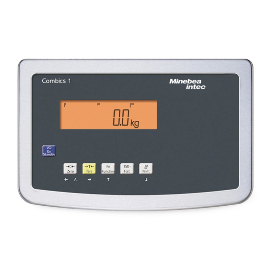
Device Description General View of the Equipment Combics 1 and 2 1 Display (for a detailed diagram, please see the chapter “Operating Design") 2 On/Off key 3 General function keys: Zero, Tare, Switch function, Adjustment/Calibration, Print/Data output (see “Operating Design") Combics 2 only 4 10 digit keypad for entering values 5 LEDs (for checkweighing and classification) -
Page 8: Installation
Installation Installation When a Combics indicator is ordered with special equipment, the desired options come pre-loaded from the factory. Storage and Shipping Conditions Once the equipment has been removed from the packaging, it may lose accuracy if subjected to strong vibration. –... -
Page 9: Getting Started
Data Interfaces chapter starting on page 102 Connecting Weighing Platforms to WP1 An analog Sartorius platform (CAPP, CAPS, IU or IF) or a commercially-available DMS load cell can be connected to the Combics indicator WP1 input. The load cell should be connected by a certified technician who has received specialized training from Sartorius. - Page 10 Securely connect the wires of the connecting cable in accordance with the terminal assignments. After you close the housing again, use a pressure gauge to check the integrity of the IP69K protection. For details, contact the Sartorius Service Center. Connecting Cables Insert all cable wires through the ferrite case, wind them around the ferrite case and then reinsert back through the ferrite case.
-
Page 11: Connecting Weighing Platforms: Combics 1
Getting Started Connecting Weighing Platforms: Combics 1 Interface PCB for ADC 2*3000e (option A8) Com 1 COM1 terminal assignments LOAD_PRINTER 11 Clear to Send (CTS) RESET_OUT 12 Data Terminal Ready (DTR) 6 3: GND 13 Data Input (RXD) 14 Data Output (TXD) 5V_OUT 15 GND 5V switched... - Page 12 Getting Started Connecting Weighing Platforms: Combics 2 Interface PCB for ADC 2*3000e (option A8) Com 1 COM1 terminal assignments (applies to all PCBs) PS/2 LOAD_PRINTER 11 Clear to Send (CTS) 21 5 V switched RESET_OUT 12 Data Terminal Ready (DTR) 22 PS2_Data 3: GND 13 Data Input (RXD)
-
Page 13: Pin Assignment Chart
Getting Started Pin Assignment Chart Models (IP44 protection) CAISL1 CAISL2 COM1 female connectors: 25-pin D-Submini female connector (DB25S) with screw lock hardware for cable gland Recommended interface connector: 25-pin D-Submini (DB25) with shielded cable clamp assembly and shield plate (Amp type 826 985-1C) and fastening screws (Amp type 164868-1) COM1 pin assignments Pin 1: Shield... - Page 14 Getting Started Cabling Diagram - Connection to a PC Use the following cables to connect a PC to the indicator in accordance with the RS-232C/V24 standard (max. cable length 15 m): Models CAISL1, CAISL2: connecting cable 7357312 Models CAIS1, CAIS2: connecting cable YCC02-D9F6 Cable Diagrams Connection assignments for the cable from the indicator to an RS-232 PC interface (COM1).
- Page 15 The printed voltage rating (see type label) must match the voltage in the place of installation. If the voltage specified on the label or the plug design of the AC adapter do not match the rating or standard you use, please contact your Sartorius office or dealer.
- Page 16 Getting Started Connecting a Barcode Scanner (Accessory, Order No. YBR02CISL) Disconnect the indicator from AC power (unplug the AC adapter) For CAISL2 models: Connect the barcode scanner via PS/2. For CAIS2 models: Please see “Pin Assignment Charts," page 13 (implemented via the YCC02-BR02 connecting cable or as option M8) NOTE: This equipment has been tested and found to comply with the limits pur- suant to part 15 of FCC Rules.
-
Page 17: Configuring Weighing Platforms
Configuring Weighing Platforms Configuring Weighing Platforms Service Mode The Service mode enables access to additional menu items in the Setup menu Purpose (setup) which are not displayed when the Service mode is not active. The most important calibration and adjustment work for the indicator and for the connected weighing platform can be carried out in the Service menu, e.g. - Page 18 Configuring Weighing Platforms Activating the Service Mode Switch to the Menu mode (see page 35). Access the Setup menu. Select Setup If a password is requested at this point, enter the service password (see Appendix) and continue with “Saving the service password." Access the U-Code menu item Select U-Code Enter the service password (see Appendix).
-
Page 19: Analog/Digital Converter (Adc)
Configuring Weighing Platforms Analog/Digital Converter (ADC) Purpose Adjust the parameters of the analog/digital converter to the connected load cell or weighing platform. After ADC configuration, the ADC in connection with the load sensor is defined as a scale. Once the ADC configuration has been locked, the indicator can no longer be used to influence weighing results. - Page 20 Configuring Weighing Platforms User-defined / o 11.8.1 FREE Grams /g 11.8.2 Kilograms /kg 11.8.3 Tons /t 11.8.21 SAVE Save configuration parameters 11.10 11.10.1 11.10.2 Factory settings/Reset menu wt.para Verifiable configuration 9.1.4 VERIF. CLASS Accuracy class 11.1 Class 11.1.4 RANGES Ranges 11.3 Single-range scale 11.3.1...
- Page 21 Configuring Weighing Platforms Setting parameters for ADC configuration Standard or verifiable configuration In ADC configuration, you must first select whether the weighing platform should be configured as a standard or verifiable (for use in legal metrology) weighing platform. – Standard configuration STANDRD (9.1.3) –...
- Page 22 Configuring Weighing Platforms Minimum load (min. load) When “Standard configuration” is used, this menu item is not displayed. The minimum load of the connected weighing platform is entered under this menu item. The minimum load for scales of class l is 20 e and 10 e for class Attention: The function of the minimum load setting is to warn operators that below this limit, the summation of tolerances might lead to significant measurement errors.
- Page 23 Configuring Weighing Platforms Configuring the A/D converter (ADC) The weighing platform must already be connected. Open the menu access switch The menu access switch is located on the back of the indicator right next to the weighing platform connection. Remove the cap. Slide the switch to the left (= “open"...
- Page 24 Configuring Weighing Platforms The A/D converter can now be treated like a standard weighing platform in connection with the load sensor. Close the menu access switch (right position) and reattach the cap. Once ADC configuration has been completed, an adjustment of the weighing platform (calibration/adjustment and linearization) must be carried out (see page 47 and “Calibration/Adjustment without Weights", page 30).
- Page 25 Configuring Weighing Platforms Procedure Open the menu access switch. If the device is part of a verified weighing facility, this will only be possible if the verification seal is broken. The weighing equipment must then be verified again. Activate the Service mode. Select the weighing platform.
-
Page 26: Entering Adjustment And Linearization Weights
Configuring Weighing Platforms Entering Adjustment and Linearization Weights Entering adjustment and linearization weights. Purpose Setup information – The Service mode must be activated in order for linearization weights to be entered under menu items 1.18.2 to 1.18.5 (see page 17). –... -
Page 27: External Linearization
Configuring Weighing Platforms Setup information – External linearization when weighing in legal metrology is only possible when the menu access switch is open. – The “external linearization" function must be allocated to the J key (menu item 1.9.6 or 1.9.7). Once linearization has been completed, the J key must be reallocated back to its original function in the Setup menu, e.g. -
Page 28: Setting The Preload
Configuring Weighing Platforms Setting the Preload – Setting the preload when weighing in legal metrology is only possible when Setup information the menu access switch is open. – The “Set Preload" function (menu item 1.9.8) must be allocated to the J key (see page 141). -
Page 29: Clearing The Preload
Configuring Weighing Platforms Deleting the Preload – Deleting the preload when weighing in legal metrology is only possible when Setup information the menu access switch is open. – The “Set Preload" function (menu item 1.9.8) must be allocated to the J key (see page 141). -
Page 30: Adjustment Without Weights
Configuring Weighing Platforms Adjustment Without Weights In the Service menu, adjustment without weights can be carried out by entering the characteristic data of the load cells. Adjustment without weights may not be carried out on weighing equipment used in legal metrology. Setup information –... -
Page 31: Operating Design
Operating Design Operating Design You can use the Combics 2 to record weight values from two weighing platforms, calculate and display weight values through application programs, and assign IDs to the samples weighed. First, use the menu to configure the indicator for the desired application (printer settings, etc.). - Page 32 Operating Design Weighing Operation Combics 1 Combics 2 Keys for all models On/Off key When in Standby mode, STANDBY is displayed. Zero key Press the key less than 2 seconds: Zero Press the key longer than 2 seconds: Displays the adjustment/configuration counter Tare key Saves the numeric input as the tare weight...
- Page 33 Operating Design Info key: Used to display application parameters and manual tare values (Info after pressing a follow-up key, e. g. )) Number keys: Used to enter numeric values To apply the value, press the corresponding function key (e.g. key ) to save the entry as a manual tare value.
- Page 34 Operating Design The Display There are two display modes: – Display for weighing (weighing values and calculated values) – Display in “Menu mode" (device settings) The figure shows the display of the Combics 2 Display in Weighing Mode Appl. 1 Appl.
-
Page 35: Menu Operating Design
Operating Design Symbols for applications: An active application is identified by a line above and below the symbol Application 1*: “Counting"/ “Neutral Measurement" “Weighing in percent" “Averaging" (animal weighing) Application 2*: “Checkweighing" “Classification" “Checkweighing toward zero" Manually batching to a target value Application 3*: “Totalizing"... - Page 36 Operating Design Entering Numbers and Letters (without a number block) – Press the key less than 2 seconds: Activate character to the left of the currently active character (when first character is active: exit the input mode without saving changes) –...
-
Page 37: Configuration
Operating Design Configuration Basic settings are made in the Menu mode by selecting the desired parameters. These are divided into the following groups (menu level 1), menu structure see page 135: – Application parameters APPLIC. – Function key FN-KEY – Device parameters SETUP –... -
Page 38: Setting Up Password Protection
Operating Design Use the ( key to exit the menu level to make additional settings if required Press the ) key longer than 2 seconds to exit the menu. Setting up Password Protection Turn on the device. While all segments are lit, briefly press the ) key. y The first item in the main menu is shown: APPLIC.. - Page 39 Operating Design To apply a character, press the ) key. Enter all additional characters of the password as described above. Press and hold the ) key to save the password. Use the ( key to exit the menu level to make additional settings if required Press the ) key longer than 2 seconds to exit the menu.
-
Page 40: Operation
Operation Operation Weighing This application is always available during operation. Features: – Zeroing by pressing ( – Storing the weight on the platform as a tare by pressing ) – Tare container weight automatically – Use a barcode scanner to enter tare weight (Combics 2) –... - Page 41 Operation Automatic printing (PROTOC menu item 7.15): When the menu item (7.15.2) is active, the first weight value that exceeds the minimum load is printed. If the menu item is also activated for automatic taring, it is only tared when the minimum load is exceeded.
- Page 42 Operation Adjustment/Configuration counter for standard scales Purpose Automatic recording of changes to adjustment and weighing parameters using two independent counters. The values remain saved for the life of the component. To display both counters, press and hold the ( key for longer than 2 seconds. y The “Configuration counter"...
- Page 43 Operation Device Parameters Password protection Access to the device parameters Setup and application parameters APPLIC. (Combics 2) can be password-protected against unauthorized changes in the Setup menu under U-CODE (see page 38). Acoustic signal An acoustic signal (single beep for active, double beep for inactive keys) is emitted when you press a key.
- Page 44 Operation Place the container on the weighing platform. y The container weight is displayed. Press the ) key to tare the scale. y The display for a tared scale with a container appears. Place a sample in the container (in this example 120.2 g) y The display for a tared scale with weighing results appears.
- Page 45 Operation y Net weight value display before it was switched. Press the p key to print a report. ACE HARDWARE GOETTINGEN Date and time for Combics 2 only 12.08.2012 15:10 -------------------- 170.2 g 50.0 g 120.2 g -------------------- Example Combics 2: Weighing: Enter value for tare using the numeric keys;...
- Page 46 Operation y The gross value is displayed. You can toggle between the gross and net display using the L key. Press the p key to print a report. GMP header (only if GMP-compliant -------------------- printout is configured, menu 7.13) 24.08.2012 15:15 Type CW1NP1-30ED-LCE Ser.no.
-
Page 47: Calibration, Adjustment
Operation Calibration, Adjustment Perform calibration to determine the difference between the value displayed and Purpose the actual weight on the platform. Calibration does not entail making any changes within the weighing equipment. During adjustment, the difference between the measured value displayed and the true weight of a sample is corrected, or is reduced to an allowable level within maximum permissible error limits. - Page 48 Operation Features – Block the J key to prevent use of the two functions Which of the following features are available depends on the described above: setup / wp-1menu Menu item 1.9. connected weighing platform. These features are “Calibration, Adjustment." configured in the Setup menu: –...
-
Page 49: Sqmin Function
Operation SQmin Function To display the allowable minimum sample quantity “SQmin” (sample quantity Purpose minimum) in accordance with the United States Pharmacopoeia (USP). According to USP guidelines, the uncertainty of measurement may not exceed 0.1% of the sample quantity when substances are weighed with the highest degree of accuracy for volume determination. - Page 50 Operation SQmin operation Determining sample weights while monitoring the minimum sample Example quantity (in this example, SQmin = 100 g) Configuration: The SQmin display must be turned on. Place the container for the sample on the scale and tare. t. Place the sample on the scale. y The minimum sample quantity is not reached (symbol k).
-
Page 51: Data Id Codes
Operation Data ID Codes This function is only available for Combics 2. You can assign codes (such as product name, batch number, etc.) for identification of measured values on printouts. Features – Assign up to six ID codes. – Assign both a name and a value to each ID code. –... - Page 52 Operation Using individual ID codes Example Enter ID code names. “Batch number" and “Customer" should be entered for ID 1 and ID 2. Open menu (see page 35) . Select and open SETUP. Select and open PRINT. Open PROTOC.. Open HEADLIN. . Select and open ID 1.
-
Page 53: Application Programs
Operation Application Programs Overview of applications and functions Combics 1 Combics 2 Keys 6 keys 17 keys plus numeric keypad Display 14-segment 14-segment plus pictograms Application Basic weighing Send print job/data record to peripheral device Label printer Connection option for second scale –... -
Page 54: Counting Z (Combics 2)
Operation Counting Z (Combics 2): With the Counting application, you can determine the number of parts which each have approximately equal weight (APPLIC.1 menu). Features – Save the reference weight “wRef" from the weighing platform – Enter the average piece weight “wRef" via the keypad –... - Page 55 Operation Entering the reference piece weight The reference piece weight (i.e., the weight of one piece) can be entered using the keypad and save with the O key. Reading the reference piece weight The reference piece weight can be read using a barcode scanner. The entered value remains active until deleted by pressing the c key or until overwritten by a new value.
- Page 56 Operation Resolution The resolution indicates the accuracy used to determine the reference weight. The default setting is “display resolution." The resolution is increased when “10- fold" or “100-fold" is selected. “10-fold" increases the resolution of the net value by one step (display resolution x 10), “100-fold" increases it two steps (display resolution x 100).
- Page 57 Operation The system can be confi gured to switch automatically to the reference platform for initialization (the measured value line shows Ref). Following initialization, you can switch to the counting platform. Setting: Applic./Applic.1/Count./REF.WP menu item 3.13. If automatic reference sample updating is enabled, the update is performed on the active platform;...
- Page 58 Operation y The result is displayed. y If automatic reference sample updating is enabled, Opt appears in the display. Print results (Configuring Printouts see page 96). nRef 38 pcs wRef + 0.003280 kg 0.373 kg 0.248 kg 0.125 kg 38 pcs -------------------- Operating Instructions Combics Indicators...
-
Page 59: Neutral Measurement Z Nm (Combics 2)
Operation Neutral Measurement Z nM (Combics 2) With this application you can measure the length, surface and volume of parts that have roughly the same specific weight. The o symbol is displayed as the unit (menu APPLIC.1). Features – Save the reference weight “wRef" from the weighing platform: –... - Page 60 Operation resolution. The resolution settings are either display resolution, display resolution 10-fold or display resolution 100-fold. Entering the reference weight The reference weight (e.g., the weight of one meter of electrical cable) can be entered using the keypad and saved by pressing the O key. Reading the reference piece weight The reference weight can be read using a barcode scanner.
- Page 61 Operation Minimum load for initialization You can set the minimum load here, i.e. the load that must be placed on the weighing platform in order to carry out the application. If the load on the platform is too light, the following will occur: –...
-
Page 62: Averaging (Animal Weighing) V (Combics 2)
Operation Example: 25 m of electrical cable is to be measured. Configuration: The “Neutral Measurement" application is selected, and printout has been set up (see “Configuration"). Place empty container on the scale. Tare the scale. This is not required if the automatic tare function is active. The tare weight is saved automatically when you place the container on the platform. - Page 63 Operation With this application, you can calculate averages from several weighing operations. It is used when either the object to be weighed (e.g. animals) or the environment during weighing are unstable. Selection and settings in the Applic. / Applic.1 / ANIM.WG menu.
- Page 64 Operation * = Factory setting Available parameter settings MIN.INIT Minimum load for initialization 1 digit* 3.6.1 1 digit 2 digits 3.6.2 2 digit 5 digits 3.6.3 5 digit 10 digits 3.6.4 10 digT. 20 digits 3.6.5 20 digT. 50 digits 3.6.6 50 digT.
- Page 65 Operation ..., 50%, 100%), configured in Setup under: Activity menu item 3.19. If the “Averaging” parameter is set to 2%, for example, and the animal or object weighs 10 kg, measurement does not begin until the fluctuation in weight value remains below 200 g during three consecutive measurements.
- Page 66 Operation Set the number of reference parts using r: 1, 2, 5, 10, 20, etc. Start the calculation of the reference piece weight. The averaging routine does not begin until the fluctuation in weight value remains below a defined threshold over three consecutive measurements. The number of sub-weighing operations remaining is shown in the numeric display.
-
Page 67: Weighing In Percent L (Combics 2)
Operation Weighing in Percent L (Combics 2) With this application, you can use your weighing platform to obtain weight readouts in percent which are in proportion to a reference weight. L is displayed as the weight unit. Selection and settings in the Applic. / Applic.1 / PERCENT menu. –... - Page 68 Operation Entering the reference percentage value The reference weight for 100% is entered using the keypad and the O key is pressed to initialize the application. Reading the reference percentage value The reference weight can be read using a barcode scanner. The entered value remains active until deleted by pressing the c key or until overwritten by a new value.
- Page 69 Operation Setting: Applic./Applic.1/PERCENT/Min.init menu item 3.6. The minimum load can be set in 10 steps from 1 to 1000 digits (see available parameters). The “digits" here refer to the scale intervals for the connected weighing platform. If the interval of the connected platform is 1 g, for example, and 1000 digits are required, you must place at least 1000 g (= 1000 intervals =1000 digits) on the weighing platform for initialization.
- Page 70 Operation Example: 100% of a sample material should be weighed. Confi guration: The “Weighing in Percent" application is selected, and printout has been set up. Place empty container on the scale. Tare the scale. This is not required if the automatic tare function is active. The tare weight is saved automatically when you place the container on the platform.
- Page 71 Operation Print the results. Printout Confi guration, see page 96 pRef 20 % wRef 0.085 kg 1.080 kg 0.675 kg 0.423 kg 100 % ------------------- Operating Instructions Combics Indicators...
-
Page 72: Checkweighing H (Combics 2)
Operation Checkweighing (Combics 2) With this application, you can check whether the sample on the weighing platform matches a target value or lies within a given tolerance range. Checkweighing also makes it easy to fill sample materials to a specified target weight. Selection and settings in the Applic. - Page 73 Operation A tare value entered manually overwrites a stored tare value (weight value). If you enter a tare value manually, a tare value (weight value) stored later overwrites the manually entered value. Setting: Applic. / TARE.FNC menu item 3.25.2 Restore factory default settings: Applic./Reset menu item 9.1. Target Checkweighing entails comparing the current weight value to a defined target.
- Page 74 Operation CTRL.SET Activate SET control output 4.3. SET output 4.3.1* OUTPUT Ready to operate 4.3.2 OP.READY OUTP.ACT Activation of outputs 4.4. 4.4.1 Always on 4.4.2 ALWAY.ON At stability 4.4.3 STABIL. Within checkweighing range 4.4.4* CHECK.RG On at stability within STAB.CHK checkweighing range 4.4.5 INPUT Parameter input...
- Page 75 Operation In the Applic./Applic.2/CHECK.WG/OUTP.ACT menu, menu item 4.4, you can make the following settings for the control outputs: – switched off – always on – on at stability – on within checkweighing range – on at stability within checkweighing range Checkweighing range Checkweighing range 30 %...
- Page 76 Operation Example 1: Checkweighing samples with a target weight of 1250 g and a tolerance range from -10 g to +30 g. The tolerance values should be entered as absolute values (lower and upper tolerance limit). Configuration: The “Checkweighing" application is selected using the setting INPUT / TAR.MN.MX, a printout has been set up (see “Configuration").
- Page 77 Operation y The LEDs next to the display indicate the results: yellow LED: sample too heavy green LED: sample in tolerance range red LED: sample too light Print the results. Note: If automatic printout of results is enabled, you do not need to press the p key.
- Page 78 Operation Enter the maximum lower deviation (in this example, 10 g). Save the lower limit value. y The maximum symbol flashes at the top of the display. Enter the maximum upper deviation (in this example, 30 g). Save the upper limit value. Proceed as described in example 1.
- Page 79 Operation Save the upper limit value. Remove the sample with the target weight from the weighing platform. The samples can now be checked one after the other. y The LEDs next to the display indicate the results: yellow LED: sample too heavy green LED: sample in tolerance range red LED: sample too light Print the results.
-
Page 80: Classification W (Combics 2)
Operation Classification (Combics 2) With this application, you can determine whether the weight of a given sample lies within the limits of a defi ned weight class (Applic.2 menu). – Classifi cation with 3 or 5 weight classes. Features Setting: Applic./Applic.2/CLASS./PARAM.2/QTY. menu item 4.8. –... - Page 81 Operation Example: Enter 100 g as the upper limit of Class 1. Then enter 15%. When working with 3 classes, this yields the following weight classes: Class 0: up to the minimum load Class 1: > minimum load - 100 g Class 2: >...
- Page 82 Operation Minimum load for initialization You can set the minimum load here, i.e. the load that must be placed on the weighing platform in order to carry out the application. If the load on platform is too light, then this is class 0. Setting: Applic./Applic.1/Count./Min.init menu item 3.6.
- Page 83 Operation In the Applic./Applic.3/CLASS./Param.2/OUTP.ACT menu, menu item 4.7, you can make the following settings for the control outputs: – switched off – always on – on at stability The “SET” output normally changes its voltage level when the current weight exceeds the minimum load.
- Page 84 Operation y The result is displayed. Print the results. Note: If automatic printout of results is enabled, you do not need to press the p key. The results are printed automatically. Printout Confi guration, see page 96 Lim1 0.110 kg Lim2 0.130 kg 0.118 kg...
-
Page 85: Totalizing S (Combics 2)
Operation Totalizing s (Combics 2) With this application, you can add weights to the totalizing memory. In addition to weight values, the number of separate values added to memory is also saved (APPLIC.3 menu). Features – You can weigh up to 999 items. –... - Page 86 Operation – Value saved automatically when the weighing platform is stable and the defi ned minimum load is exceeded. If the defi ned minimum load is not exceeded, you can save the item manually by pressing the O key. Regardless of these settings, the current value cannot be saved automatically unless the platform is unloaded before the next sample is placed on it.
- Page 87 Operation Example: Totalizing weight values. Confi guration: The “Totalizing" application is selected, and printout has been set up. Setting: SETUP / PRINT/PROTOC. menu item 7.6 Component log: menu item 7.7. Total data record: Menu item 7.8 Place the fi rst weight on the weighing platform. y The weight value is displayed.
- Page 88 Operation Toggle the display between individual value and total. End totalizing. y Confi gured total data record is printed. 1.346 kg 0.346 kg 1.000 kg ------------------ Operating Instructions Combics Indicators...
-
Page 89: Net Total Formulation R (Combics 2)
Operation Net Total Formulation R (Combics 2) With this application, you can weigh in different components up to a defi ned total. Each component is saved in the net-total memory (Applic.3 menu). Features – Weigh in up to 999 components in series –... - Page 90 Operation Minimum load The minimum amount that a component must weigh before it can be saved in net- total memory. Setting: Applic./Applic.3/NET TOT menu item 3.6 Once the limit is exceeded by the load, the value can be saved. If the load on platform is too light, the following will occur when you try to save a value: –...
- Page 91 Operation Tare the scale. This is not required if the automatic tare function is active. The tare weight is saved automatically when you place the container on the platform. y The prompt to fill and save the first component is shown. Place the first component into the container (in this example, 1100 g).
- Page 92 Operation y The value displayed equals the weight of components added up to now plus the current weight on the platform. Place the third component into the container until the desired total weight is reached (in this example, 2000 g). y The total weight is displayed.
-
Page 93: Combining Application Programs
Operation Combining Application Programs The following table shows how the applications described can be combined. The basic weighing function is available at all times; it does not need to be combined with a computational function. Select programs one after the other: Toggle using the D key Application 1 (Basic Function) Application 2 (Monitoring Function) Application 3 (Cumulative-value Function) - Page 94 Operation Place a number of parts in the container for the reference quantity (in this example, 10 pcs). Start the calculation of the reference piece weight. y If the weight is too light, an error code is shown in the main display Inf 29. Reduce the minimum load setting or increase the reference sample quantity setting and the number of parts in the container.
- Page 95 Operation y The number of pieces is saved automatically. Unload the scale: Remove the samples Perform further counting operations as desired. Toggle display from individual value to total. End the portioning options and print the fi nal evaluation. Confi gured printout: Total -------------------- nRef 10 pcs...
-
Page 96: Configuring Printouts
Operation Configuring printouts You can individually define each measurement printout. This should be carried out Purpose after setting the applications since some data in the printout is application- dependent. In the “Print parameters" menu, single, component and total data records can be configured, which contain the available print items for the respective applications. - Page 97 Operation Date without time 7.14 DAT/TIM Automatic printout after stability 7.15 AUT.ONCE Flex print 7.16 FLEX.PRN Decimal separator 7.17 DEC.SEP. Alibi memory 7.18 ALIB.MEM Restore factory default settings RESET Setting factory settings – The rows of the protocol list can be called up and activated individually. Example: see under Confi...
- Page 98 Operation Example: Standard printout for data output from the “Counting" application Confi guration: – Application: Application 1: Counting – Then access Setup: Printout: Printer 1: “Individual: print by pressing p" Select the Setup menu. Select and open the Print submenu. Select and open the PROTOC.
- Page 99 Operation y The counter value is increased by one. Press the k key until the “Reference weight" entry appears in the display. Press the ) key to save the selection. You can now select additional print items in the same way. To exit print item entry, press the ( key until APPLIC.
-
Page 100: Product Data Memory (Combics 2)
Operation Product Data Memory (Combics 2) Purpose The product data memory stores initialization data and user data (product and tare values). Features – The product data memory has 100 memory cells for product or tare values. For example, you can store 80 sets of application data and 20 tare values –... - Page 101 Operation Example: Using the Counting application with a stored average piece weight. Confi guration: Application: Counting (COUNT.) Saving the average piece weight Start the application. Determine the average piece weight using one of the methods described above. Enter the memory cell number using the keypad, and press and hold the R key (min 2 seconds).
-
Page 102: Data Interfaces
The free cable ends are connected via the screw terminals. Warning when using third-party RS-232 connecting cables: The pin assignments may not be compatible with Sartorius equipment. Check the pin assignment against the cabling diagrams and disconnect any lines that are not assigned. Failure to do so may cause malfunction, damage or even completely ruin your indicator and/or peripheral device(s). - Page 103 – PC (RS-232 interface) – 2nd weighing platform (Combics 2 only, RS-232 interface) – External checkweighing display (stop light) via a digital I/O (Sartorius standard) The following devices can also be connected to the optional UniCOM: – PC (RS-232 interface) –...
- Page 104 Data Interfaces Connecting a printer The COM1 standard interface, the optional UniCOM universal interface or both can be used as a printer interface. Use as a communications interface The data protocol can be set to the following operating modes for operation as a communications interface: –...
-
Page 105: (Datprot)
Data Interfaces Configuring the Data Interface as a COM Port (datprot) You can configure the interface as a COM port in either COM1 or UniCOM, “Data Protocol" (datprot) menu item. This is a simple ASCII interface. SBI communication Data output is configured under menu items 6.1 and 6.3: –... -
Page 106: Data Input Format
Data Interfaces Data Input Format You can connect a computer to your scale to send commands controlling weighing instrument functions and applications via the interface port. All commands use the same data input format. They start with the ESC character (ASCII 27) and end with a carriage return (CR;... -
Page 107: Data Output Format
Data Interfaces Data Output Format Each line in a print job can contain up to 22 characters (up to 20 printable characters plus two control characters). The fi rst 6 characters, called the “data header”, identify the subsequent value. You can suppress the header under menu item 7.2 in the “Printouts”... - Page 108 Data Interfaces Example: Output weight value of +1255.7 g Position 1 2 3 4 5 6 7 8 9 10 11 12 13 14 15 16 + * * * 1 2 5 5 . 7 * g * * CR LF Position 1: Plus +, or minus - or space Position 2:...
- Page 109 Data Interfaces Error message 2 3 4 5 6 7 8 9 10 11 12 13 14 15 16 17 18 19 20 21 22 t a t * * * * * E r r * * # # * * * * CR LF t a t * * * * * E r r * # # # * * * * CR LF *: Space...
-
Page 110: (Printer)
Data Interfaces External Keyboard Functions (PC Keyboard) Setting: Setup /BARCODE / EXT.KEYB The alphanumeric key codes implemented here are specific to the German keyboard layout. The following alphanumeric characters are used (some require the “Shift” key): a - z, A - Z, 0 - 9, <space>, and these characters: ,.\+’<>/»$@%/();=:_?* Function keys: PC keyboard Combics 2... -
Page 111: Gmp-Compliant Printouts
Data Interfaces Configuring Printouts Printouts are configured in the Setup menu under “Printouts" (setup / print / protoc.). This should be carried out after configuring the application since some data in the printout is application-dependent. You can configure a separate printout for each interface Each printout is comprised of different information blocks that can be activated or deactivated via multiple selection in the menu. - Page 112 Data Interfaces 1) = Combics 2 only Weighing platform WP 1: Dash line -------------------- Date/Time 14.01.2012 09:43 Combics type Type CAISL2 Combics serial no. Ser.no. 12345678 Software version of application Vers. C2 100.280810 Software version of basic version BVers. 01-62-01 Dash line -------------------- Weighing platform WP 2 (XBPI protocol):...
-
Page 113: Sample Printout
Data Interfaces "Neutral Measurement" "Checkweighing" application: Sample Printouts application: The initialization data contains the For details on the individual The initialization data block target weight, the min. weight and information blocks, see “Configuring contains the reference sample the max. weight. The results data Printouts”, above. - Page 114 Data Interfaces Example with 2 transactions: Clearing the preload printout GMP-compliant printouts HEADER LINE1 -------------------- Linearization printout HEADER LINE2 14.01.2012 13:50 -------------------- 14.01.2012 09:43 Type CAISL2 14.01.2012 13:00 -------------------- Ser.no. 12345678 Type CAISL2 1.400 kg Vers. C2 100.280810 Ser.no. 12345678 0.200 kg BVers.
-
Page 115: Error Codes
New EEPROM loaded (Service) Turn the scale off and then on again. If the error code Err 340 Err340 is still displayed, please contact your local Sartorius Service Center RAM has lost data; battery is dead Leave the scale connected to power for at least 10 hrs. -
Page 116: Care And Maintenance
Care and Maintenance Service Regular servicing by a Sartorius technician will extend the service life of your device and ensure its continued weighing accuracy. Sartorius offers its customers service contracts with regular maintenance intervals ranging from one month to two years. -
Page 117: Safety Inspection
Disconnect the power supply to the device (unplug the power cord from the mains supply) and make sure the device cannot be used for the time being. Notify your nearest Sartorius Service Center. Maintenance and repair work may only be carried out by service technicians: –... -
Page 118: Disposal
In Germany and several other countries, Sartorius itself assumes responsibility for the return and conformant disposal of its electronic and electrical products. These products may not be placed with household waste or brought to collection centers run by local public disposal operations —... -
Page 119: Specifications
Specifications Technical Data ADC scale interface 2*3000e (option A8) When used in standard applications (as opposed to legal metrology): ≤ 31250 d – Display resolution 625 d – Lowest permissible input signal Using the Equipment in Legal Metrology: Accuracy class l, m Verification scale intervals when used as: ≤... - Page 120 Specifications ADC scale interface 10,000e (option A10, A20) When used in standard applications (as opposed to legal metrology): ≤ 100,000 d – Display resolution – Lowest permissible input signal 1510 d Using the Equipment in Legal Metrology: Accuracy class l, m Verification scale intervals when used as: ≤...
-
Page 121: Device Dimensions
Device Dimensions Device Dimensions All dimensions are given in millimeters Operating Instructions Combics Indicators... -
Page 122: Accessories
Accessories Accessories Product Order No. Verifiable data printer with date/time and statistics functions YDP20-0CE with LCD display. – 5 + 50 m paper rolls for data printer 6906937 – Replacement ink ribbon cartridge for printer 6906918 Verifiable strip and label printer with barcode printout, paper width 108 mm, with adapter cable (12-pin round male connector) and external power supply. - Page 123 7 TTL-compatible inputs (0 - 30 V), YCC02-RELAIS01/02 connection cable required YSB02 Relay box to connect Combics 2 to external control units, YCC02-RELAIS01/02 connection cable required VF3033 Software SNLE Sartorius Nice Label Express Software YAD02IS WinScale for Windows YSW03 SartoCollect YSC02 Other functions...
- Page 124 – for printer YDP12/04IS, 9-pin D-SUB plug, 6 m YCC02-D09M6 – for printer YDP20-0CE or PC, 9-pin D-SUB socket, 6 m YCC02-D09F6 – for Sartorius scales, 25-pin D-SUB plug, 6 m YCC02-D25M6 – for various accessories, 25-pin D-SUB socket, 6 m YCC02-D25F6 –...
-
Page 125: Documents List
For information on verification and legal regulations currently applicable in your country, and to obtain the names of the persons to contact, please contact your local Sartorius office, dealer, or Service Center. -
Page 126: Declarations Of Conformity
Declarations of Conformity Declaration of Conformity Operating Instructions Combics Indicators... - Page 127 Declarations of Conformity Operating Instructions Combics Indicators...
- Page 128 Declarations of Conformity Operating Instructions Combics Indicators...
-
Page 129: Ec Type-Approval Certificate
Declarations of Conformity Operating Instructions Combics Indicators... -
Page 130: Test Certificate
Test Certifi cate Operating Instructions Combics Indicators... -
Page 131: Plates And Markings
Plates and Markings Operating Instructions Combics Indicators... - Page 132 Plates and Markings Operating Instructions Combics Indicators...
- Page 133 Plates and Markings Operating Instructions Combics Indicators...
- Page 134 Plates and Markings Operating Instructions Combics Indicators...
-
Page 135: Menu Structure
Menu Structure Menu Structure Overview of the complete menu structure; the individual setting parameters are listed on the following pages. The indicator only displays the menus that correspond to the available hardware. Setting and selection applications (see page 136) Applic. Basic weighing function, Counting z , Neutral measurement znM, Animal weighing j, Weighing in - Applic.1 percent % applications... - Page 136 Menu Structure Combics 1 application menu * = Factory setting Applic. WEIGH. param.1 min.init Minimum load for automatic taring 1 digit* 3.5.1 1 digit 2 digits 3.5.2 2 digit 5 digits 3.5.3 5 digit 10 digits 3.5.4 10 digT. 20 digits 3.5.5 20 digT.
- Page 137 Menu Structure REF.WP Reference weighing instrument 3.13 No platform selected 3.13.1* NO WP Weighing platform 1 3.13.2 WP 1 Weighing platform 2 3.13.3 WP 2 Neutral measurement Applic./Applic.1 NEUTR.M min.init Minimum load for application 1 digit 3.6.1* 1 digit 2 digits 3.6.2 2 digit ...
- Page 138 Menu Structure DEC.PLCS Decimal places in displayed result 3.10 None 3.10.1 NONE 1 decimal place 3.10.2 1 Dec.Pl 2 decimal places 3.10.3 2 DEC.PL 3 decimal places 3.10.4 3 Dec.Pl SAVE WT. Parameter for saving weight values 3.11 With stability 3.11.1* STABIL.
- Page 139 Menu Structure PRINT Automatic Printing 4.10 Manual 4.10.1* MANUAL Automatic 4.10.2 AUTOMAT Applic.3 net.tot. Net total formulation Applic./Applic.3 min.init Minimum load for application 1 digit 3.6.1* 1 digit 2 digits 3.6.2 2 digit ... see “Weighing" 1000 digits 3.6.10 1000 di. PRT.SAV.
- Page 140 Menu Structure Resets all applications to factory settings Applic. / Reset RESET Restore all applications to factory default settings Yes (restore factory settings) 9.1.1 No (retain user-defi ned settings) 9.1.2* Menu key assignment for the k key * = Factory setting Combics 2: fn-key 2ND.UNIT Display 2nd weight unit*...
- Page 141 Menu Structure AUSTR.CT Austrian carats/K 1.7.17 Tola/tol 1.7.18 TOLA Baht/bat 1.7.19 BAHT Mesghal/MS 1.7.20 MESGHAL Tons/t 1.7.21 TONS 1.DIS.DIG. Display accuracy Show all decimal places 1.8.1* -1.WT.CHA Reduced by 1 digit 1.8.2 10-fold increased resolution 1.8.14 RES.*10 Increase resolution by 2 scale intervals 1.8.15 +DIV.
- Page 142 Menu Structure setup / WP-1 / intern. Param.2 2.WT.UNIT 2nd weight unit (depends on the weighing platform type) not for use in legal metrology Grams /g 3.1.2* GRAMS Kilograms /kg 3.1.3 KILOGR. Carats/ct 3.1.4 CARATS Pounds/lb 3.1.5 POUNDS Ounces/oz 3.1.6 OUNCES Troy ounces/oz 3.1.7...
- Page 143 Menu Structure DAT.PROT. Data protocols setup /com-1 SBI* Config. BAUD Baud rate 5.1.1 5.1.2 5.1.3 1200 5.1.4 1200 2400 5.1.5 2400 4800 5.1.6 4800 9600 5.1.7* 9600 19200 5.1.8 19200 PARITY Parity Space space Only if 7 data bits is selected 5.2.2 5.2.3* Even...
- Page 144 Menu Structure Printer Printer configuration setup /com-1 YDP20 CONFIG. BAUD Baud rate 1200 5.1.4* 1200 2400 5.1.5 2400 4800 5.1.6 4800 9600 5.1.7 9600 19200 5.1.8 19200 PARITY Parity Space space Only if 7 data bits is selected 5.2.2 5.2.3* Even 5.2.4 even...
- Page 145 Menus 1.10 to 9.1 same as for WP1 ADC-232 Menus 1.1 to 9.1 same as for WP1 RS-485* IS-485 Connect Sartorius IS weighing platform Menus 1.1 to 1.8 same as for WP1 Calibration/Adjustment 1.9 Ext. calibration/adjustment; default weight 1.9.1* External calibration/adjustment;...
- Page 146 Menu Structure Time-dependent automatic data output 1 display update 6.3.1* 2 display updates 6.3.2 10 display updates 6.3.4 100 display updates 6.3.7 Data output: line format For raw data: 16 characters 7.2.1 For other applications: 22 characters 7.2.2* Data output: sign format Plus sign deactivated 7.3.1 Plus sign activated...
- Page 147 Menu Structure setup / CTRL IO Input paramet EXT.KEYB Function for external key Trigger p key function* 8.4.1 PRINT PRNT.LNG. Trigger p key function (press and hold) 8.4.2 Trigger ) key function 8.4.3 TARE ISO.TEST Trigger J key function 8.4.4 Trigger k key function 8.4.5 SCALE.NO.
- Page 148 Menu Structure setup / barcode Save value directly as reference* REFERNC. Save value as tare value Tare Save as ID 1 Enter value on display (triggered when a key is pressed) Input External keyboard ext.keyb Save value as tare or ID code, depending on barcode header Header setup / print PROTOC.
- Page 149 Menu Structure setup / UTILIT. 8 SIGNAL Acoustic Signal 8.2.1* 8.2.2 Keys Release keypad Release all 8.3.1* ALL + All locked 8.3.2 - ALL -NUM.PAD. Number pad locked 8.3.3 -SCALE.N. n key locked 8.3.4 ( key locked 8.3.5 - ZERO ) key locked 8.3.6 - TARE...
- Page 150 Menu Structure setup / SQmin display SQmin value display GMP PRT. GMP-compliant printout setup / alib.mem Deletes the Alibi memory (Service only) clear Entry of the save intervals in days (0 to 255) period Menu info (device information) * = Factory setting Service date info / service Input: day.month.year (e.g.
- Page 151 Menu Structure ADC settings menu * = Factory setting ADC.CON standrd. Standard configuration 9.1.3 Ranges 11.3 RANGES Single-range scale 11.3.1 SINGLE Multi-interval scale 11.3.2 MULT.INT Multiple-range scale 11.3.3 MULT.RNG SINGLE Single-range scale 11.4 Scale interval d 11.4.1 Max. load 11.4.4 MAX.
- Page 152 Menu Structure Available weight units 11.7 WT.UNIT User-defi ned / o 11.7.1 FREE Grams /g 11.7.2 Kilograms /kg 11.7.4 … Tons /t 11.7.21 Pound:ounces / lb oz 11.7.22 CAL.UNIT Calibration / Adjustment unit 11.8 User-defi ned /o 11.8.1 FREE Grams /g 11.8.2 Kilograms /kg 11.8.3...
-
Page 153: Index
Index Index EC type-approval certifi cate Accessories Entering calibration weight Accessories for connection to a PC Entering geographical data Acoustic signal Entering linearization weights Activating the service mode Equipment settings overview ADC, analog/digital converter Equipment supplied Adjustment without weights Error messages Animal weighing External keys Applications advice... - Page 154 Index Safety inspection Safety instructions Sample printout SBI communication Service Service menu Service password Setting parameters Confi guration Setting the preload Setting the time Setting up password protection Shutoff, automatic SMA communication Technical data Totalizing Type-approval certifi cate Universal printer Unpacking Using in legal metrology Verifi...
- Page 155 Appendix: Guide to verification Operating Instructions Combics Indicators...
-
Page 156: Appendix
Select the required language version by clicking on the any purpose whatsoever, either in whole or in part, without the corresponding language. express written permission of Sartorius. All rights defi ned under Select the required indicator at the top of the page. copyright law are reserved by Sartorius. -
Page 157: Appendix: General Password
Appendix: General password Appendix: General password After selecting the “Setup" menu item a request to enter the access password “Code" will be displayed for 2 seconds. y The first digit in the display flashes. Numbers and the point can be entered via the number pad. Combics 2 Combics 1 and 2 Select characters using the k and p keys... - Page 158 Operating Instructions Combics Indicators...
- Page 159 Operating Instructions Combics Indicators...
-
Page 160: Ex-Safety Information
Ex-Safety Information Explosion-safe area Explosion-risk area Zone 2 or Zone 22 Gas: Group IIC, temperature class T4 Dust: Group IIIC, Tmax 80°C Ambient temperature: -10°C … +40°C … 1. Mains Connection Use an explosion-protected connector Connector from equipment supplied Connection alternatives Protect connector from Note 16) - Page 161 Ex-Safety Information Explosion-risk area Zone 2 or Zone 22 Explosion-safe area Gas: Group IIC, temperature class T4 Dust: Group IIIC, Tmax 80°C Ambient temperature: -10°C … +40°C 3. Connecting Weighing Platforms Data output with nominal supply Note 8) Indicator voltage CAIS.
- Page 162 Ex-Safety Information These safety instructions apply to installation, use, maintenance and repair The device (CAIS. indicator, CAAP weighing platform..-……-……, CAW complete scale…-……-…...) is suitable for use in potentially explosive atmospheres of Zone 2 (Group IIC, temperature class T4 or T6 for weighing platforms) and Zone 22 (Group IIIC; surface temperature 80°C) according to EU Directive 94/9/EC and applicable harmonized European standards.
- Page 163 In the event of repair, use only original spare parts supplied by the manufacturer. Any modifications to the instrument (except by persons authorized by Sartorius) cause loss of conformity for use in Zone 2 and Zone 22 explosion-risk areas and invalidate all guarantee claims.
- Page 164 Sartorius Weighing Technology GmbH Weender Landstrasse 94–108 37075 Goettingen, Germany Phone +49.551.308.0 Fax +49.551.308.3289 www.sartorius-mechatronics.com Copyright by Sartorius, Goettingen, Germany. No part of this publication may be reprinted or translated in any form or by any means without the prior writ- ten permission of Sartorius.
Need help?
Do you have a question about the Combics Series and is the answer not in the manual?
Questions and answers