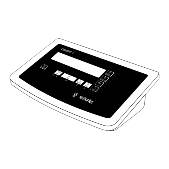
Sartorius combics 1 Operating Instructions Manual

Sartorius combics 1 Operating Instructions Manual

Indicators
Hide thumbs Also See for combics 1:

Advertisement

Operating Instructions
Sartorius Combics 1| Combics 1 plus | Combics 2
Models CISL1 | CISL1N | CISL2 | CIS1 | CIS1N | CIS2
Indicators
98648-010-85

Advertisement

Table of Contents
loading
Need help?

Need help?

Do you have a question about the combics 1 and is the answer not in the manual?

Questions and answers

Summary of Contents for Sartorius combics 1

  • Page 1 Operating Instructions Sartorius Combics 1| Combics 1 plus | Combics 2 Models CISL1 | CISL1N | CISL2 | CIS1 | CIS1N | CIS2 Indicators 98648-010-85...
  • Page 2: Intended Use

    – Equipped with a range of interfaces for flexible use – Password-protected from unauthorized changes in parameters (optional) Combics 1 plus speeds up your routine procedures with: – Input functions for tare values through numeric keypad – Option for 2 alphanumeric lines to identify samples –...
  • Page 3: Table Of Contents

    Contents 2 Intended Purpose 89 Data Interfaces 91 Pin Assignment Charts 3 Contents 93 Installing the Interface Cable 94 Cabling Diagram 4 Warnings and Safety Precautions 95 Connecting the External Rechargeable Battery Pack 5 Getting Started 95 Connecting a Bar Code Scanner 95 Synchronization 6 General View of the Equipment 96 Configuring the Data Interface...
  • Page 4: Warnings And Safety Precautions

    – EU legislation requires that a control seal be affixed to the verified device. The control seal consists of a sticker with the “Sartorius" logo. This seal will be irreparably damaged if you attempt to remove it. If any of the verification...
  • Page 5: Getting Started

    Getting Started Unpacking the Indicator Connecting the Indicator to AC Power If you have a Class A digital device, you § Unpack the equipment and check it § Check the voltage rating and the plug need to comply with the FCC statement immediately for any visible damage.
  • Page 6: General View Of The Equipment

    General View of the Equipment Display and keypad: Combics 1 and Combics 1 plus Display and Keypad: 1 Display (for details, see “Operating Design") 2 Zero key 3 On/off key 4 Tare key 5 Function key (toggle gross/net, weight unit or to 10 + higher...
  • Page 7: Operating Design

    Operating Design Keys Weighing/Measurement I Press to enter data (either ID code The operation of Combics 1, Combics 1 or tare value, depending on sub- plus and Combics 2 involves just a few sequent key; e.g., ) for tare) Input Through the Keypad keys.
  • Page 8 (Counting application) GMP-compliant printing in progress Numeric display; e.g., shows (Combics 1 plus and Combics 2 only) reference value (Combics 2 only) Battery symbol showing status of rechargeable battery (empty outline indicates battery is drained)
  • Page 9: Configuration (Operating Menu)

    10-key numeric keypad Navigation and input in the operating menu are implemented using the keys below the display (on Combics 1 plus, Display of Menu Settings numeric values can be entered using The illustration above shows all of the...
  • Page 10: Operation

    – Delete tare values by pressing 0 50 digits To do this, the “Store value as tare" and ) or E and ) (Combics 1 100 digits (tare) menu item must be selected 200 digits under “Setup >...
  • Page 11 Calibration/Configuration Features of the Configuration Device parameters Counter: Counter on Standard – Limited to a count of 9999 Password Weighing Instruments – Counter set to “P 0000" when the You can prevent unauthorized changes hardware is first put into operation in the device settings (“Setup") and Purpose –...
  • Page 12 Operating Example Switch on the Combics, zero the weighing instrument, tare the container weight, place sample in container, toggle display to gross weight, 2nd weight unit or 10-fold increased resolution Switch on the Combics All display segments are shown for approx. 1 second (self-test) 8888888 Display with no load on weighing instrument Zero the weighing instrument...
  • Page 13 Display with tared weighing instrument and sample in container 1202 Toggle display; readout depends on your settings: gross weight 1702 (in this example, 50 g for container + 120.2 g substrate) or display in 2nd weight unit (in this example, kg) or display with 10-fold increased resolution 12023 Return to previous readout...
  • Page 14 Operating the Combics 1 plus Example: Combics 1 plus: Weighing with tare value entered using the numeric keypad; generate printout of results Switch on the Combics 1 plus The automatic self-test runs. Once a readout is shown, Combics 1 plus is automatically zeroed and ready to operate.
  • Page 15 Toggle to display of net value Print the results -------------------- Start of GMP header (only if GMP-compliant printout is configured) 05.04.2004 10:09 Model CIS1N Ser.no. 12345678 Vers. 1.0001.04.4 BVers. 01-33-01 -------------------- End of GMP header ACE HARDWARE Header lines GOETTINGEN Batch no.
  • Page 16 Operating the Combics 1 plus Example: Combics 1 plus: Weighing with varying tare values; generate printout of results, delete tare values Switch on the Combics 1 plus The automatic self-test runs. Once a readout is shown, the Combics is automatically zeroed and ready to operate.
  • Page 17 Print the results 6.433 kg 4.183 kg 0.250 kg 2.000 kg -------------------- Enter a zero (“0") using the keypad Save the value entered. This deletes tare values; the display shows the gross value Print the results 6.433 kg 0.000 kg 6.433 kg --------------------...
  • Page 18: Individual Id Codes

    Operating the Combics 1 plus Individual ID Codes – Print ID codes: Refer to the Setup menu for menu item numbers. (Identifiers) Data is output to COM1 menu item 7.7.x) or UniCOM (menu item 7.8.x). You can assign ID codes (such as prod- uct name, batch number, etc.) while...
  • Page 19 Example: Entering ID code values. Enter “123.456" and “678.9" as values for ID codes 1 and 2. See “Entering the Password” in the chapter entitled “Configuration" for details on how to enter ID code names. 1 2 3 . Enter value for ID code 1 (in this example, 123.456) 4 5 6 Confirm value for the first ID code 6 7 8...
  • Page 20: Calibration And Adjustment

    Operation Calibration and Adjustment Features – Display altitude and geographical Which of the following features latitude or acceleration of gravity after are available depends on the weighing CAL is shown at the beginning of the Purpose instrument: calibration procedure (menu item The accuracy of weighing results must 8.12.2).
  • Page 21 Position the calibration weight on the weighing instrument The difference between the weight value and the true mass is displayed, with ± sign. External calibration Calibration record is printed, if adjustment was not performed and the process was stopped by pressing ( Nom.
  • Page 22: Counting Z

    Operating the Combics 2 Counting Before the quantity on the weighing Application Parameters: Counting instrument can be calculated, the With the Counting application, you can 3. 5. Minimum Load for Automatic Taring and average piece weight must be entered determine the number of parts that Automatic Printing in the application.
  • Page 23 Storage Parameter Reference Sample Updating Counting with The reference weight is saved when In the Application settings under 3.12, Two Weighing Instruments the weighing instrument has stabilized. you can define whether the reference You can use two weighing instruments “Stability" is defined as the point at sample is updated automatically.
  • Page 24 Operating the Combics 2 Example: Place empty container on the weighing instrument Tare the weighing instrument (repeatedly, if necessary) Set the desired reference sample quantity (in this example, 20) Place the corresponding number of pieces (20) in the container Confirm reference sample weight...
  • Page 25 Add more parts to the container (in this example, 18 pcs) 0pt is displayed if automatic reference sample updating is enabled 0pt 38 Toggle the display from piece count to weight < 2 sec. Toggle to Info mode Piece count is displayed Toggle to the next display mode Reference sample quantity is displayed (>...
  • Page 26: Neutral Measurement Z Nm

    Operating the Combics 2 To calculate the result correctly, the Application Parameters: Neutral Measurement Neutral Measurement Z nm average weight of a reference quantity When the Neutral Measurement 3. 5. Minimum Load for Automatic Taring must be known (in the example below, and Automatic Printing application is selected, you can use your the reference is 1 meter of electrical...
  • Page 27 Storage Parameter Neutral Measurement with The reference weight is saved when Two Weighing Instruments the weighing instrument has stabilized. You can use two weighing instruments “Stability" is defined as the point at simultaneously with the Neutral Measure- which fluctuation of a measured value ment application.
  • Page 28 Operating the Combics 2 Example: Determine the length of an amount of electrical cable after weighing in the defined reference unit value Place empty container on the weighing instrument Tare the weighing instrument (repeatedly, if necessary) Set the desired reference value (in this example, 2) Place a sample corresponding to the reference quantity in the container (in this example, 2 meters of electrical cable) Confirm reference sample weight...
  • Page 29 Remove the reference material and place the sample to be measured on the weighing instrument (in this example, 8 meters of electrical cable Print results 734.1 g 200.0 g 534.1 g --------------------...
  • Page 30: Checkweighing O

    Operating the Combics 2 Checkweighing entails comparing Application Parameters: Checkweighing Checkweighing O the current weight value to a defined When the Checkweighing application is 3. 5. Minimum Load for Automatic Taring and target. The target value has a tolerance Automatic Printing selected, you can check whether sample range which can be entered either as 3.
  • Page 31 Display Digital Input/Output Interface Checking Range The result of a measurement is shown The Checkweighing application supports Target weight 30 % 170% either as a weight value or in relation the digital input/output interface. Lower Upper to the target. You can toggle between There are 4 control lines, or outputs, limit limit...
  • Page 32 Operating the Combics 2 Example: Initialize the Checkweighing application by taking over the weighed value as target; select percentage to define tolerance range (menu item 4.5.2) Delete any existing initialization data Begin initialization The middle segments of the bar graph flash to prompt the placement of the weight on the weighing instrument Place the weight for the target on the weighing instrument (in this example, 100.0 g) 1000...
  • Page 33 Target value is displayed 1000 Optional: Toggle to the next display mode Percentage for limits is displayed Optional: Toggle to the next display mode Weight value for the lower limit (minimum) is displayed Optional: Toggle to next display mode (weight value for the upper limit is displayed) Optional: >...
  • Page 34 Operating the Combics 2 Example: Check the weight of a sample; use Tolerance Limit display mode Place a load of unknown weight on the weighing instrument If the weight is under the lower tolerance limit, LL is shown in the tolerance limit display (load is too light) (the weight display shows the measured weight value) If the weight is within the tolerance range (in this example, 103.2 g), 1032...
  • Page 35: Classification O Cl

    Operating the Combics 2 To use the Classification application, Application Parameters: Classification Classification O cl you need to enter the delimiters that With the Classification application, 3. 5. Minimum Load for Automatic Taring separate one class from another. and Automatic Printing you can determine whether the weight 3.
  • Page 36 Operating the Combics 2 Minimum Load for Initialization and Digital Input/Output Interface Min. load Max. load Defining the Class 1 Lower Limit The Classification application supports Class The minimum load defines the the digital input/output-interface. lower limit for Class 1 (i.e., the delimiter There are 4 control lines, or outputs, between Classes 0 and 1).
  • Page 37 Example: Initialize the Classification application by taking over weighed values (menu item 4.9.1) to define 3 classes (menu item 4.81.) Delete any existing initialization data Begin initialization The minus sign of the bar graph flashes to prompt the weight for the upper limit of the first class.
  • Page 38 Operating the Combics 2 Store the weight value as the upper limit for the second class When initialization is complete, the display shows the class to which the weight on the weighing instrument belongs. Optional: < 2 sec. Toggle to Info mode to view stored values Upper limit of Class 1 is displayed Optional: Toggle to the next display mode...
  • Page 39 Example: Determine the class of a given weight Place a load of unknown weight on the weighing instrument The display shows which class the weight falls into; in this example, Class 2 (10 g – 20 g) Toggle display to weight readout The weight of the load is shown (in this example, 17.3 g) Print results PET STORE...
  • Page 40: Weighing In Percent

    Operating the Combics 2 To determine the weight of a sample Application Parameters: Weighing in Percent Weighing in Percent L relative to a reference weight, you 3. 5. Minimum Load for Automatic Taring must enter the reference weight in the and Automatic Printing With the Weighing in Percent appli- weighing instrument.
  • Page 41 Storage Parameter Weighing in Percent with Display The reference weight is saved when Two Weighing Instruments With the Weighing in Percent application, the weighing instrument has stabilized. You can use two weighing instruments the result can be displayed as a remainder “Stability"...
  • Page 42 Operating the Combics 2 Example: 0 00 Place empty container on the weighing instrument Tare the weighing instrument 0 00 (repeatedly, if necessary) Set the desired percentage (in this example, 50%) 0 50 Place reference material corresponding to the reference percentage in the container Confirm the reference weight...
  • Page 43 Remove the reference material and place the sample to be measured on the weighing instrument The percentage of the reference weight equal to the sample is displayed Print results 641.2 g Residue 200.0 g 441.2 g 21.00 % -------------------- 641.2 g Loss 200.0 g 441.2 g...
  • Page 44: Averaging (Animal Weighing)

    Operating the Combics 2 Averaging – Automatic start with preset number Application Parameters: Averaging (Animal Weighing) of subweighing operations (Animal Weighing) V 3. 5. Minimum Load for Automatic Taring The subweighing operations begin and Automatic Printing With the Averaging application, you when the weight of the sample/animal 3.
  • Page 45 Example: Place empty container on the weighing instrument Tare the weighing instrument (repeatedly, if necessary) Set the desired number of measurements (in this example, 20) Place 1st animal in bowl Start measurement Measurement starts as soon as all criteria are met. The number of subweighing operations remaining is shown in the numeric display.
  • Page 46 Operating the Combics 2 Print results x-Net + 24.6 g Unload weighing instrument Once the weighing instrument is unloaded (i.e., the load = less than 1/2 the minimum load), the current weight value is displayed.
  • Page 47: Net-Total Formulation R

    Net-Total Formulation R Application Parameters: Net-Total Formulation Minimum Load for Automatic Storage/ Transfer of Values 3. 5. Minimum Load for Automatic Taring The minimum load for automatic When the Net-Total Formulation and Automatic Printing storage or transfer of weight values is application is selected, you can weigh 3.
  • Page 48 Operating the Combics 2 Example: Weigh in 3 components, display total weight after 2nd component (Additive mode) Place empty container on the weighing instrument Container weight a prompt for first component are shown Tare the weighing instrument Add the first component (in this example, 68.3 g) The weight of the first component is displayed Store the weight of the first component ACE HARDWARE...
  • Page 49 Add the second component (in this example, 82.7 g) The weight of the second component is displayed Store the weight of the second component Cmp002 82.7 g Component weight is printed The weighing instrument is tared automatically and the component counter value is increased by one (prompting the next component) Toggle to the Additive mode The value displayed equals the weight of all components added up to now plus...
  • Page 50: Totalizing Σ

    Operating the Combics 2 Totalizing Σ The Combics has a totalizing memory Application Parameters: Totalizing for adding individual net and gross 3. 5. Minimum Load for Automatic Taring values. There are two ways to store With the Totalizing application, you and Automatic Printing weight values in the totalizing memory: 3.
  • Page 51 Minimum Load for Automatic Printout Storage/Transfer of Values Under menu item 3.17 you can configure The minimum load for automatic whether a printout is generated manually, by pressing p (3.17.3), or automatically storage or transfer of weight values is configured under menu item 3.6. when a weight value is stored in the Once the load on the weighing instru- totalizing memory (3.17.2 or 3.17.3).
  • Page 52 Place the sample on the weighing instrument Weight value is displayed 1029 Store weight value in totalizing memory Main display: Current weight on the weighing instrument 1029 Numeric display: Transaction counter (in this example: 1) SARTORIUS GOETTINGEN 06.02.2002 12:15 -------------------- 102.9 g 0.0 g 102.9 g...
  • Page 53 SARTORIUS GOETTINGEN 06.02.2002 12:19 -------------------- 215.2 g 0.0 g 215.2 g Main display: Totalizing memory content plus current weight Numeric display: Transaction counter (in this example: 2) End totalizing Total data record is printed, as configured under 7.9. or 7.10.
  • Page 54: Configuration

    = Setting/function available on Combics 1 plus only = Setting/function available on Combics 2 only = Setting/function available on Combics 1 plus and Combics 2 only First level display 2nd level display Function...
  • Page 55 Example: Change language from English to English with U.S. date/time format Switch on the Combics While all segments are lit, press the ) key First level of menu for selecting the application program Appl is shown Select the Lang menu item (press k repeatedly until Lang is displayed) Select Lang device parameter The currently active language is shown Select the U.S.
  • Page 56 Configuration Example: Assign a password to protect the application program settings “Appl" and the device parameters “Setup" from unauthorized changes (in this example: AB2) Switch on the Combics While all segments are lit, press the ) key First level of menu for selecting the application program Appl is shown Select the Setup menu item (press k repeatedly until Setup is displayed) Open the Setup menu...
  • Page 57 Enter the second character using the p and k keys (in this example: b) Store character Enter the third character using the p and k keys (in this example: 2) Store character To enter other characters, use the p and k keys and press ) to confirm Store the password Exit this menu level to configure other menu settings, or >...
  • Page 58: Operating Menu Overview (Parameters)

    Configuration Operating Menu Overview (Parameters) = Setting/function available on Combics 1 plus only = Setting/function available on Combics 2 only = Setting/function available on Combics 1 plus and Combics 2 only * Factory setting Menu Appl Application Programs Basic Weighing Function 3.
  • Page 59 appl Z nm Neutral Measurement 3. 5. Minimum Load for Automatic Taring and Automatic Printing Numeric menu as for Weighing 3. 6. Minimum Load for Initialization Numeric menu as for Counting 3. 7. Automatic Taring: 1st Weight Tared 3. 7. 1 * 3.
  • Page 60 Configuration appl 3.21. Static Display After Load Removed 3.21. 1 * Display is static until unload threshold reached Display is static until c is pressed 3.21. 2 9. 1. Factory Settings for All Application Programs 9. 1. 1 9. 1. 2 * Checkweighing 3.
  • Page 61 appl O CL 4. 8. Number of Classes 4. 8. 1 * 3 classes 4. 8. 2 5 classes 4. 9. Parameter Input 4. 9. 1 * Weight values 4. 9. 2 Percentage 4.10. Automatic Printing 4.10. 1 * 4.10. 2 9.
  • Page 62 Configuration appl 3.17. Printout when Value is Stored in Totalizing Memory 3.17. 1 Automatic printout of results: Off Generate printout with complete standard configuration each time O is pressed 3.17. 2 * Generate printout with complete standard configuration only once when O is pressed 3.17.
  • Page 63 Setup Device Parameters Password prompt displayed, if a password is configured wp-1 Weighing Instrument 1 (Display designation of this menu level: 1) 1. 1. Adapting Weighing Instrument to Ambient Conditions (Adapt Filter) 1. 1. 1 Very stable conditions 1. 1. 2 Stable conditions 1.
  • Page 64 Configuration Setup wp-1 1. 9. Calibration, Adjustment 1. 9. 1 Ext. calibration/adjustment; default weight 1. 9. 3 Ext. calibration/adjustment; weight can be selected under menu item 1.18.1 Press ) -> 2 sec: blocked 1. 9.10 1.10. Calibration/adjustment sequence 1.10. 1 Calibration with automatic adjustment 1.10.
  • Page 65 Setup Com1 Interface 1 (Display designation of this menu level: 2) off * Weighing Instrument 2 rs-232 * RS-232 sbi-std SBI Standard Version sbi-app SBI trade version (for legal metrology) bpi-232 XBPI-232 1. 1. through 1.8. Numeric menu as for WP1 1.
  • Page 66 Configuration Setup Com1 datProt sbi * 6. 3. Time-dependent automatic data output 6. 3. 1 * 1 display update 6. 3. 2 2 display updates 6. 3. 4 10 display updates 6. 3. 7 100 display updates 7. 2. Data Output: Line Format 7.
  • Page 67 Setup Com1 datProt SMA Interface Function 5. 1. Baud Rate 5. 1. 1 150 baud 5. 1. 2 300 baud 5. 1. 3 600 baud 5. 1. 4 1200 baud 5. 1. 5 2400 baud 5. 1. 6 4800 baud 5.
  • Page 68 Configuration Setup Com1 Printer Uni-pri Universal Interface 5. 1. Baud Rate 5. 1. 1 150 baud 5. 1. 2 300 baud 5. 1. 3 600 baud 5. 1. 4 1200 baud 5. 1. 5 2400 baud 5. 1. 6 4800 baud 5.
  • Page 69 ADC-232 1. 1. through 9.1. Numeric menu as for WP1 rs-485 * RS-485 is-485 * Connection of Sartorius IS Weighing Platform 1. 1. through 1.8. Numeric menu as for WP1 1. 9. Calibration, Adjustment 1. 9. 1 * Ext. calibration/adjustment; default weight 1.
  • Page 70 Configuration Setup uniCom1 Printer Printer Configuration YDP01IS YDP01IS line* Strip printer label Label printer lab ff Label printer with manual feed YDP02 YDP02 models 5. 1. through 5.4. Numeric menu as for COM1 YDP03 YDP03-0CE 5. 1. through 5.4. Numeric menu as for COM1 YDP02IS YDP02IS line*...
  • Page 71 Setup crtl in External Switch (Display designation of this menu level: 4 ) 8. 4. Function of Remote Switch (Universal) p key function 8. 4. 1 * p (> 2 sec) function 8. 4. 2 ) key function 8. 4. 3 ) (>...
  • Page 72 Configuration Setup prtprot 7.10. Optional “UniCOM" Interface Print results when c pressed, in “Totalizing" and “Net-Total" applications 7.10. 1 * Header lines 1, 2 7.10. 2 * Date and time 7.10. 4 * Weighing instrument designation 7.10. 5 * Result from the application program 7.10.
  • Page 73: Device Information

    Setup time Time Input example: 10.07.41 (hours.minutes.seconds) date Date Input example: 01.05.02 (day.month.year) U.S. Mode: (month.day.year) code Password Set, change and delete (max. 8 characters); example: 12345678 Info Device Information Service Service Information 10.04.02 Service Date term Indicator CISL2 Model 10405355 Serial number 1.0101.10.01...
  • Page 74: Service

    WP1. The load cell should be connected only by a trained and authorized Sartorius technician. Any installation work that does not conform to the instructions in this manual will result in for- feiture of all claims under the manufacturer's warranty.
  • Page 75 § Connecting the cable: – Guide the wires through the ferrite ring, wrap them around the ring once and guide them through the ferrite ring again – Attach the wires securely to the screw terminals Wiring assignments: Signal name Meaning BR_POS Bridge supply voltage (+) SENSE_POS...
  • Page 76: Service Menu

    Service Service Menu The following advanced functions are available in the service mode: Purpose The following menu items are The “Service" menu contains additional appended to the “Date" (DATE) and configuration options in the operating “Password" (CODE) menu items: menu (setup) that are only available –...
  • Page 77 Activating the Service Mode Select the Setup menu item Open the Setup menu If password input is prompted, enter the service access code (see Appendix) and confirm input to continue If no password prompt is displayed: Select the Code menu item (Press k repeatedly until code is displayed) Select the Code menu item and enter the service access code (see Appendix) Confirm the service access code...
  • Page 78: Configuring The Analog/Digital Converter

    Service Configuring the Analog/ – Configure the A/D converter in the If you return to the highest level of the Setup menu (in service mode) for the numeric menu without saving changes Digital Converter (ADC) first weighing instrument under “WP-1" (menu item 11.10), all changes made and for the second weighing instrument up to that point are lost.
  • Page 79 11.6 Multiple-range Weighing Instrument 11.6.1 Scale interval d 11.6.4 Range 1 11.6.5 Range 2 11.6.6 Range 3 11.6.7 Max. cap. 11.7 Available Weight Units 11.7.1 User-defined / o 11.7.2 Grams /g 11.7.4 Kilograms /kg 11.7.21 Tons / t 11.8 Calibration/Adjustment Unit 11.8.1 User-defined /o 11.8.2...
  • Page 80 Service Descriptions of the Scale Interval d Range 1, Range 2, Range 3 Scale interval d indicates the resolution of Here you can enter the limits for each Individual Menu Items for the weighing instrument. The scale interval of the weighing ranges. When a limit is A/D Converter Configuration d can be entered only in increments of 1, exceeded, the accuracy changes.
  • Page 81 Configuring the A/D Converter (ADC) Open the menu access switch. § Remove the cap that covers the menu access switch on the left-hand side of the back of the indicator housing. § Move the switch to the right (towards the interface connectors; “open" position) Activate the service mode (see page 77) Select the weighing instrument to be configured (in this example, WP-1) Under menu item 9.1, select “standard"...
  • Page 82: Geographical Data

    Service Entering Geographical Data Note on Settings – Following calibration/adjustment, – Geographical data can be entered enter the geographical data for the only in the service mode and only with place of installation under menu items Purpose the menu access switch open. 1.20.1 through 1.20.3 and select menu To perform an external adjustment –...
  • Page 83: Entering Calibration And Linearization Weights

    Entering Calibration/Adjust- – Enter calibration/adjustment and Procedure linearization weights in the Setup menu – Activating the service mode (required ment and Linearization for the first weighing instrument under only for entering linearization weights) Weights “WP-1" and for the second weighing –...
  • Page 84: Function Of The ) Key (> 2 Sec)

    Service Function of the ) Key – External linearization with default Following linearization or after weights (menu item 1.9.6) a preload is set or cleared, the normal (> 2 sec) – External linearization with the function of the ) key (> 2 sec) linearization weights specified under must be reset in the Setup menu (e.g., Purpose...
  • Page 85: External Linearization

    External Linearization Note on Settings Following external linearization, External linearization can only be close the menu access switch and reset the ) key (> 2 sec) to its previous performed on verified weighing instruments when the menu access function (e.g., external calibration/ switch is open.
  • Page 86: Set Preload

    Service Setting the Preload Note on Settings The preload can be set only when the menu access switch is open. – The “set preload" function must be assigned to the ) key (> 2 sec) (menu item 1.9.8) (see page 85). After setting the preload, close the menu access switch and reset the ) key (>...
  • Page 87: Clear Preload

    Clearing the Preload Note on Settings The preload can be cleared only when the menu access switch is open. – The “clear preload" function must be assigned to the ) key (> 2 sec) (menu item 1.9.9) (see page 85). After clearing the preload, close the menu access switch and reset the ) key (>...
  • Page 88: Calibration/Adjustment Without Weights

    Service Calibration/ – The nominal capacity must be entered Procedure in kg. – Open the menu access switch Adjustment without Weights – The resolution must be entered in – Activate the service mode kg and must be in agreement with the –...
  • Page 89: Data Interfaces

    Internal or external The pin assignments in the cable Factory setting: 4 to 20 mA, internal power supply might not be compatible with Sartorius equipment. Check all pin assignments Interface connector: CISL1, CISL1N and CISL2 indicators (IP44 protection): against the cabling diagrams and dis- 25-contact D-Sub female connector connect any lines that are not assigned.
  • Page 90 Connecting a Printer – External rechargeable battery pack The standard COM1 port or the optional – Bar code scanner (Combics 1 plus and universal UniCOM interface (or both) Combics 2 only) can be used as a printer interface.
  • Page 91: Pin Assignment Charts

    Pin Assignment Charts Pin assignments, COM1: Pin Assignment Chart: 2nd Interface: Connection of external rechargeable Pin 1: Shield battery and bar code scanner (optional Models CISL1, CISL1N and CISL2 Pin 2: Data output (T+D) UniCOM interface not installed) (IP44-protected): Pin 3: Data input (R+D) Pin 4: Not connected Pin 1: Shield Female Connectors COM1 and UniCOM:...
  • Page 92 Data Interfaces Models CIS1, CISN1 and CIS2 Models CIS1, CIS1N and CIS2: Connection (IP67-protected): Terminals on the PCB of weighing instrument Connection of open cable ends to COM1: 11-20 1-10 UniCOM: 1- 4 1-10 (page 72) terminal screws inside the indicator COM1 interface connections: 18 19 11 12 13 14 15 16...
  • Page 93: Installing The Interface Cable

    Peripheral devices should be connected to the interfaces only by a trained and authorized Sartorius technician. Any installation work that does not conform to the instructions in this manual will result in forfeiture of all claims under the manufacturer's warranty.
  • Page 94: Cabling Diagram

    Data Interfaces Cabling Diagram (Adapter Cable for PC) (Model CISL1/CISL1N/CISL2: adapter cable 7357312; model CIS1/CIS1N/CIS2: connecting cable YCC02-D9F6). Diagram for connecting a computer or other peripheral device to the indicator using the RS-232-C/V24 standard and cables up to 15 m (50 ft.) long: Indicator Cabling diagram...
  • Page 95: Connecting The External Rechargeable Battery Pack

    Once the mains supply is The weighing instrument interface restored, the Combics automatically <–– XON ––– (Sartorius Balance Interface = SBI) has switches back to normal operation. ––– byte –––> transmit and receive buffers. You ––– byte –––>...
  • Page 96: Configuring The Data Interface As A Com Port

    Data Input Format Command Meaning F6: Trigger I key function kF6_ Interface as a COM Port You can connect a computer to your (Combics 1 plus only) (datProt) indicator to send commands controlling F7: g key function kF7_ weighing instrument functions and...
  • Page 97: Data Output Format

    Data Output Format Error Codes Position 1 2 3 4 5 6 7 8 9 10 11 12 13 14 15 16 You can output the values displayed in the line for measured values and the weight unit with or without a data ID code. * * * E r r * * # # * * * * CR LF The first 6 characters, called the data header, show the data ID code * * * E r r * # # # * * * * CR LF...
  • Page 98 Data Interfaces Error Codes Example (output of value: +1255.7 g): Position 1 2 3 4 5 6 7 8 9 10 11 12 13 14 15 16 17 18 19 20 21 22 Position 1 2 3 4 5 6 7 8 9 10 11 12 13 14 15 16 17 18 19 20 21 22 S t a t * * * * * E r r * * # # * * * * CRLF G # * * * * + * * * 1 2 5 5 .
  • Page 99: Configuring The Data Interface As A Printer Port

    The block is terminated with a blank line. Block 2: Date/Time Example: format of Block 3 (not on Combics 1) (Counting application) Example: format of Block 2: 21.01.2001 16:02 1.402 kg 0.200 kg...
  • Page 100 14.01.2002 09:45 Date/time To generate GMP-compliant printouts Name: Field for operator signature on labels, select menu item 7.11.2. Blank line -------------------- Dotted line ) Not applicable for Combics 1 indicators ) Combics 2 indicators only...
  • Page 101: Sample Printouts

    Sample Printouts Neutral Measurement Application Checkweighing Application The “Initialization data" block contains The “Initialization data" block contains the reference sample quantity and the nominal, minimum and maximum For details on the individual information reference weight. The “Results" block weights. The “Results" block always blocks, see “Configuring Printouts"...
  • Page 102 Data Interfaces Classification Application “Total” printout: Totalizing Application The “Initialization data" block contains -------------------- The “Initialization data" block is empty. the upper limits of Classes 1 through 4. If this block is enabled for the printout, The “Results" block contains gross, net S-Comp+ 3.400 kg a blank line is output.
  • Page 103 Component printout GMP-compliant Printouts “Clear preload” record: (menu item 3.17.2) Linearization record: -------------------- The entire standard printout is gene- -------------------- 14.01.2002 13:50 rated for each component. 14.01.2002 13:00 Model CISL2 Example: 2. Print second transaction: Model CISL2 Ser.no. 12345678 Ser.no. 12345678 Vers.
  • Page 104: Error Codes

    Err 101 - 104 Key is stuck Release key or Key pressed when switching on the Combics Contact your local Sartorius Service Center Err 320 Operating program memory Contact your local (EEPROM) defective Sartorius Service Center...
  • Page 105: Care And Maintenance

    § Notify your nearest Sartorius Service Do not open the indicator while it is Cleaning Stainless Steel Surfaces Center or the International Technical carrying current.
  • Page 106: Recycling

    Recycling Sartorius products are packaged to ensure safe shipment using environ- mentally friendly materials. After suc- cessful installation of the indicator, you should return this packaging for recy- cling because it is a valuable source of secondary raw material. For information on recycling options,...
  • Page 107: Overview

    Overview Specifications When used in standard applications (as opposed to legal metrology): – Display resolution <31,250 d In legal metrology: l, m Accuracy class Verification scale intervals when used as a – Single-range instrument <3125 e – Multi-interval instrument <3125 e –...
  • Page 108: Dimensions (Scale Drawings)

    Dimensions (Scale Drawings) All dimensions are given in millimeters...
  • Page 109: Accessories

    Verifiable strip and label printer with thermal print head, paper width 101 mm, with adapter cable (12-pin round male connector) and external power supply. YDP12IS-0CE-UV Sartorius “NICE Label Express" software required for putting the printer into operation. Adapter cable YCC01-01CISLM3 required for Combics model CISL indicator.
  • Page 110 Information on (e.g., for bar codes with variable font size, graphics, etc.) request Sartorius WinScale driver software for Windows 95/98/2000/NT. Displays the weighing instrument readout on your PC monitor and provides secure memory for storing data that is subject to legal control.
  • Page 111 Product Order No. Retainer for mounting bar code scanner on floor-mounted column, bench stand or column of Combics complete scale YBH01CWS Plate for mounting printer on the floor-mounted column or bench stand YPP01CWS Set of castors for YBP03CIP/S column base, with 2 guide castors, 2 lockable castors YRO03CI Anti-theft locking device...
  • Page 112: Declaration Of Conformity

    Sartorius equipment and waltungsamt – Eichwesen) from February for any connections of cables or equipment 15, 1993. not supplied by Sartorius and must check For additional information on and, if necessary, correct these modifica- the C mark on Sartorius equipment, tions and connections.
  • Page 118: Index

    Index Page Page Key: ) (> 2 sec) A/D converter Access code Keys, functions of 7, 9 Accessories Acoustic signal 11, 72 Language, setting 55, 73 Activating the service mode Legal metrology: use in ADC, configuring Linearization weights, entering Adjustment Linearization, external Analog/digital converter Animal weighing...
  • Page 119: General Password

    General Password When you select “Setup", the password prompt is displayed for 2 seconds. The first cursor position of the password flashes. repeatedly , Entering the password: – Press k to select numbers and press ) to confirm. repeatedly , Press either k (to scroll through numbers from 0 up to 9) or p (to scroll repeatedly ,...
  • Page 120 – Software: MS Excel® version 8 declaration of compatibility. of Sartorius AG. All rights defined under (included with MS Office 97) or later copyright law are reserved by – VGA graphics adapter, 800x600 pixels, Start Sartorius AG.
  • Page 121 Sartorius AG Weender Landstrasse 94–108 37075 Goettingen, Germany Phone +49.551.308.0 +49.551.308.3289 www.sartorius.com Copyright by Sartorius AG, Goettingen, Germany. All rights reserved. No part of this publication may be reprinted or translated in any form or by any means without the prior written permission of Sartorius AG.

Table of Contents

Save PDF