
Related Manuals for Sartorius PT-10


Summary of Contents for Sartorius PT-10
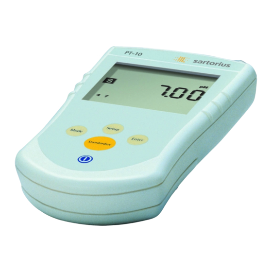
- Page 1 Service Manuals Sartorius Troubleshooting PT-10, PT-10P Portable pH/mV-Meter WPT5005-e02081...
-
Page 2: Table Of Contents
Contents 03 Service Policy for Exchanging Portable pH/mV Meters (PT-10) 03 Troubleshooting PT-10 Testing the UP-10 Meter Testing the pH Electrode 05 Quick Calibration 05 Complete Calibration 06 Changing Keypad 09 Changing Display 12 Changing Main PCB 17 Changing Battery Connector... -
Page 3: Service Policy For Exchanging Portable Ph/Mv
Service Policy for Exchanging Portable pH/mV Meters (PT-10) - Defective meters shall be exchanged for new ones and will be sent to our central repair workshop (ZW) in Goettingen, Germany, for reworking. - At your special request, meters can be sent to ZW in Goettingen for repair. -
Page 4: Testing The Ph Electrode
Testing the pH Electrode Testing the pH Electrode Testing the pH Electrode Testing the pH Electrode Testing the pH Electrode • Connect the pH electrode to the BNC connector • Place the clean electrode into a pH 7 buffer • Place in mV mode: reading should be 0 ± 30 mV Outside of this range indicates a bad electrode •... -
Page 5: Quick Calibration
Quick Calibration 1. Place the shorting cap on the BNC connector. 2. Press the mode and enter keys simultaneously. 3. The instrument will display „CAL“ on the screen. When the countdown is finished the meter is calibrated. 4. If the reading is now 0 +/- 0.1 mV (7.00 pH) calibration was successful. If the reading is outside of this range or unstable, replace the main PCB board. -
Page 6: Changing Keypad
Changing Keypad NOTE: Do not service with power to the instrument! 1. Remove the battery cover. 2. Using a Phillips screwdriver, remove the two screws in the battery compartment and the two screws near the strap opening. screws PT_001.JPG 3. Lift the zif socket labeled „Keypad“ and remove the keypad cable. Keypad zif &... - Page 7 5. Place the new keypad membranes on the cover (outline first followed by the keypad), feeding the cable through the slot. 6. Place the cable back into the appropriate zif socket. PT_003.JPG 7. Place the overlay on top of the membrane keypad. 8.
- Page 8 9. Place silicon drops in four places (both top corners and the bend on both sides). 10.Place the cover on the base. 11.Replace all four screws. PT_002.JPG...
-
Page 9: Changing Display
Changing Display NOTE: Do not service with power to the instrument! 1. Remove the Battery Cover. 2. Using a Phillips screwdriver, remove the two screws in the battery compartment and the two screws near the strap opening screws PT_001.JPG 3. Lift the zif socket labeled „Keypad“ and remove the keypad cable. 4. - Page 10 5. Remove the two screws and washers holding the display with PCB on the cover. screws PT_005.JPG 6. Clean, and make dust free, the display and the cover. 7. Reassemble by following steps 3-5 in reverse order. PT_006.JPG...
- Page 11 8. Before sealing, plug in and confirm display and keypad are working. PT_007.JPG 9. Place silicon drops in four places (both top corners and the bend on both sides). 10.Place the cover on the base. 11.Replace all four screws. PT_002.JPG...
-
Page 12: Changing Main Pcb
Changing Main PCB NOTE: Do not service with power to the instrument! 1. Remove the Battery Cover. 2. Using a Phillips screwdriver, remove the two screws in the battery compartment and the two screws near the strap opening. screws PT_001.JPG 3. - Page 13 6. Remove the main PCB by gently holding back tabs and snapping board out (will be held by silicon on ATC port). 7. Remove tape and clean surface of base. PT_008.JPG 8. Place two pieces of double-sided tape on either side of the indentation taking care that they do not touch the indentation.
- Page 14 9. Place silicon on all three sides of the bottom of the ATC cover. 10.Place the ATC cover onto the main PCB board around the ATC connector. PT_010.JPG 11.Place silicon around the front of the ATC connector filling the gap between the connector and ATC cover, 12.Place the O-ring on the ATC connector.
- Page 15 13.Place the large O-ring around the BNC connector. 14.Gently hold back the tabs and insert the board into place. PT_008.JPG 15.Using silicon completely fill the empty space behind the BNC connector. PT_012.JPG...
- Page 16 16.Reattach the battery connector, display cable and keypad cable to the main PCB. 17.Apply power to the instrument and confirm operation. PT_002.JPG 18.Place silicon drops in four places (both top corners and the bend on both sides). 19.Place the cover on the base. 20.Replace all four screws.
-
Page 17: Changing Battery Connector
Changing Battery Connector NOTE: Do not service with power to the instrument! 1. Remove the Battery Cover. 2. Using a Phillips screwdriver, remove the two screws in the battery compartment and the two screws near the strap opening. screws PT_001.JPG 3. - Page 18 5. Thread the new connector in from the battery compartment to the inside of the instrument. 6. Tie a knot in the cable near the base and pull tight. PT_013.JPG 7. Place Black Max (Loctite 380) around the knot being sure it does not pass though the hole into the battery compartment.
- Page 19 9. Put the connector onto the battery cable. 10.Reattach connector to main PCB. 11.Put in battery and confirm operation before sealing. PT_015.JPG 12.Place silicon drops in four places (both top corners and the bend on both sides). 13.Place the cover on the base. 14.Replace all four screws.
- Page 20 Sartorius AG. The status of the information, specifications and illustrations in this manual is indicated by the date given below. Sartorius AG reserves the right to make changes to the technology, features, specifications, and design of the equipment without notice.
Need help?
Do you have a question about the PT-10 and is the answer not in the manual?
Questions and answers