
Related Manuals for Keysight Technologies CX3300 Series


Summary of Contents for Keysight Technologies CX3300 Series
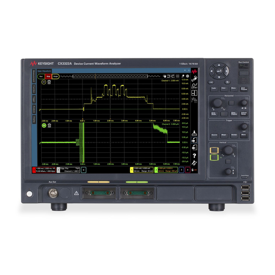
- Page 1 Keysight Technologies CX3300 Series Device Current Waveform Analyzer CX3322A 2-Channel Model CX3324A 4-Channel Model User’s Guide...
- Page 2 Notices Copyright Notice U.S. Government Rights Warranty © Keysight Technologies 2016-2020 The Software is “commercial computer THE MATERIAL CONTAINED IN THIS software,” as defined by Federal Acquisition DOCUMENT IS PROVIDED “AS IS,” AND IS No part of this manual may be reproduced in Regulation (“FAR”) 2.101.
- Page 3 COMPLIANCE WITH GERMAN NOISE REQUIREMENTS This is to declare that this product is in conformance with the German Regulation on Noise Declaration for Machines (Lärmangabe nach der Maschinenlärminformation-Verordnung -3.GSGV Deutschland). Herstellerbescheinigung • GERÄUSCHEMISSION Lpa < 70 dB am Arbeitsplatz normaler Betrieb nach DIN 45635 T.
- Page 4 CX3300 Device Current Waveform Analyzer - At a Glance Input Maximum Dynamic range Analog Digital Model Memory depth channel sample rate (ADC bits) band wid th channel CX3322A 1 GSa/s 14 (high speed mode) and 50 MHz 4/16/64/256 Mpts 16 (high resolution mode) 100 MHz 4/16/64/256 Mpts 200 MHz...
- Page 5 Ease of use with high performance Two operation modes; Scope mode and Data Logger mode (option STG) • Two or four analog input channels with various wide-range and high-resolution • sensors Front-panel interface provides easy access to the controls needed for •...
- Page 6 Removable solid-state drive and USB 2.0 and 3.0 ports Solid-state drive for fast boot-up • Saves the setup data to reuse it another time. • Saves and restores the setup and waveform data. • Saves data in the dedicated report format. •...
- Page 7 In This Guide This guide provides the information you need to begin using Keysight Technologies CX3300 Device Current Waveform Analyzer. This guide consists of the following chapters. "Setting Up the CX3300" This chapter describes the installation requirements and other setup information.
-
Page 9: Table Of Contents
Contents 1 Setting Up the CX3300 Inspection ........... . .14 Installation . - Page 10 User Calibration ..........32 Calibration.
- Page 11 Setting Up Triggers ..........59 Setting the CX3300 for an Edge Trigger .
- Page 12 Forcing a Default Setup ......... . 84 SSD Recovery .
- Page 13 Keysight CX3300 Series Device Current Waveform Analyzer User’s Guide Setting Up the CX3300 Inspection Installation Turning On the CX3300 Changing the Administrator Password Verifying Basic Operation Changing Windows Environment Turning Off the CX3300 Maintenance This chapter describes how to set up your CX3300, connect power and...
-
Page 14: Inspection
If the shipping container is damaged or the cushioning materials show signs of stress, notify the carrier as well as your Keysight Technologies sales office. Keep the shipping materials for the carrier’s inspection. The Keysight Technologies office will arrange for repair or replacement at Keysight Technologies’... -
Page 15: Installation
Setting Up the CX3300 Installation Installation “Safety Considerations” • “Environmental Characteristics” • “Bench Installation” • “Connecting a Mouse, Keyboard, and LAN Cable” • “Connecting Power” • “Connecting the CX1100” • Safety Considerations Refer to “Safety Information” on page 103 for general safety information. Before installation or operation, check the CX3300 and review this guide for safety warnings and instructions. - Page 16 Setting Up the CX3300 Installation Table 1-1 Environmental Characteristics Characteristics Environment Indoor use only Ambient temperature Operating: 0 C to 40 C Storage: 20 C to 60 C Operating: up to 80% relative humidity, non-condensing, at 40 C Humidity Storage: up to 90% relative humidity, non-condensing, at 60 C Altitude Operating: up to 2,000 m (6,561 ft.) Storage: up to 4,600 m (15,092 ft.)
-
Page 17: Bench Installation
Setting Up the CX3300 Installation Bench Installation Position the CX3300 where it will have sufficient clearance for airflow around the back and sides. Fan cools the instrument by drawing air through the sides and exhausting it out the back. Do not block the air intake at the sides and the exhaust at the rear of the CX3300. Minimum clearances for bench operation are 25 mm along the sides and 75 mm along the back. -
Page 18: Connecting A Mouse, Keyboard, And Lan Cable
Setting Up the CX3300 Installation Connecting a Mouse, Keyboard, and LAN Cable A mouse and keyboard can be plugged into the USB host ports. Three host ports are on the front panel and four host ports are on the side panel. If you want to connect the CX3300 to the site LAN, connect your LAN cable to the RJ-45 connector on the side panel. -
Page 19: Connecting Power
Setting Up the CX3300 Installation Connecting Power Connect the power cord to the IEC 60320 connector on the CX3300 rear panel. If the wrong power cord was shipped with your instrument, contact Keysight Technologies. The AC input on the back of the CX3300 is a universal AC input. It accepts nominal line voltages in the range of 100 to 240 VAC. - Page 20 Setting Up the CX3300 Installation Option 904 Option 906 Option 912 Option 917 Plug: SB Plug: NEMA Plug: SEV 1011, • Plug: IS 1293 and • • • 107-2-D1, 250 V, 6-15P, 250 V, 10 A 250 V, 10 A IS 6538, 250 V, 10 A 10 A PN: 8120-3996...
-
Page 21: Connecting The Cx1100
Setting Up the CX3300 Installation Connecting the CX1100 The CX1100 other than the CX1152A can be connected to the analog input channels on the CX3300 front panel. 1. Attach the connector of the CX1100 to the desired channel. 2. Fasten the screws on the connector to assure the contact. 3. -
Page 22: Turning On The Cx3300
Setting Up the CX3300 Turning On the CX3300 Turning On the CX3300 Press the Standby switch to turn on or off the CX3300. The switch is located in the lower left corner of the CX3300 front panel. Standby switch Whenever it is likely that the ground protection is impaired, you must make the instrument inoperative and secure it against any unintended operation. -
Page 23: Changing The Administrator Password
Setting Up the CX3300 Changing the Administrator Password Changing the Administrator Password On the CX3300 with the Windows operating system, the default Administrator user account password is “keysight4u”. Change the Administrator password to something more secure. Keysight CX3300 User’s Guide, Edition 5... -
Page 24: Verifying Basic Operation
Setting Up the CX3300 Verifying Basic Operation Verifying Basic Operation The following procedures verify the basic operation which monitors the Calibration Output signal. “If You Use the CX1101A/CX1102A/CX1103A” • “If You Use the CX1104A” • “If You Use the CX1105A” •... -
Page 25: If You Use The Cx1104A
Setting Up the CX3300 Verifying Basic Operation The 2 mA DC current is applied from the Aux Out terminal. 5. Click the close (x) button located in the upper right corner on the Configuration dialog box to close the dialog box. 6. -
Page 26: If You Use The Cx1105A
Setting Up the CX3300 Verifying Basic Operation 2. Press the 1 (yellow), 2 (green), 3 (blue), or 4 (red) key associated with the channel connected to the Aux Out terminal and enable the channel. 3. Press the Menu key several times to open the Configuration dialog box. The Menu key is located above the Horizontal control on the front panel. -
Page 27: Procedure
Setting Up the CX3300 Verifying Basic Operation Procedure 1. Set the slide switch on the test adapter to the 50 OHM. See Figure 1-6. 2. Connect the coaxial cable between the BNC jack connector on the test adapter and the Aux Out terminal on the CX3300 front panel. 3. -
Page 28: Changing Windows Environment
Setting Up the CX3300 Changing Windows Environment Changing Windows Environment Exit the CX3300 application before changing any Windows operating system settings or installing any software. In the default setting, the Administrator password is “keysight4u”. The Administrator password should be changed for security. Changing Operating System Settings Many Windows operating system settings can be changed to suit your own personal preferences. -
Page 29: Turning Off The Cx3300
Setting Up the CX3300 Turning Off the CX3300 Turning Off the CX3300 Press the Standby switch. The CX3300 will go through a normal Windows operating system shutdown process. If a DUT is connected to the CX3300, do not turn the CX3300 off to prevent damage on the DUT. -
Page 30: Maintenance
Setting Up the CX3300 Maintenance Maintenance Maintenance should be performed periodically to keep the CX3300 in good condition. If problems arise, contact your Keysight Technologies sales office. “Cleaning” • “Diagnosis” • “User Calibration” • “Calibration” • “Troubleshooting” • “Servicing” •... -
Page 31: To Perform Diagnosis
Setting Up the CX3300 Maintenance Front Panel LED test • Touch Panel test • LCD test • Self-Test • ADC Open Offset test • Sensor Floating PS test • Sensor DC Offset Control test • It is recommended to perform the diagnosis for the following condition or purpose. -
Page 32: User Calibration
It is recommended to perform the calibration once a year at least. For the calibration and adjustments, contact your Keysight Technologies sales office. Trained service personnel will perform the calibration and adjustments. -
Page 33: Troubleshooting
Setting Up the CX3300 Maintenance Troubleshooting If any problem is found on the CX3300/CX1100, perform the following troubleshooting. 1. Isolate the problem between the CX3300 and the CX1100. See Figure 1-7. 2. Isolate the problem between the CX1100 and the sensor head. See Figure 1-8. - Page 34 Setting Up the CX3300 Maintenance Figure 1-7 CX3300/CX1100 Troubleshooting START If CX1100 is not detected by CX3300, disconnect it from the analog input channel and connect it to another channel. Is CX1100 detected? Perform Fail Self-Test. Pass Perform Sensor Floating Fail PS test.
- Page 35 Setting Up the CX3300 Maintenance Figure 1-8 CX1100 Troubleshooting START Is it CX1104A? Do you have a “working” resistive sensor head? Is it CX1103A, CX1105A, or CX1151A? Replace the resistive sensor head Replace with the “working” one. CX1103A, CX1105A, or CX1151A. Is it CX1152A? Perform...
- Page 36 Setting Up the CX3300 Maintenance Figure 1-9 CX1152A Troubleshooting START Replace the grabber of the failing channel with a “working” grabber. Does the problem still exist? Replace the probe lead of the failing channel with a “working” probe lead. Does the problem still exist? Do you have a “working”...
-
Page 37: Servicing
Also refer to CX1100 User’s Guide. If you are shipping the product to Keysight Technologies for service, perform the following steps before shipping. 1. Contact your nearest Keysight Technologies sales office for information on obtaining an RMA number and return address. - Page 38 Setting Up the CX3300 Maintenance For servicing the CX3300 mainframe, you do not need to send the CX1100 and the sensor heads. For servicing the CX1101A or the CX1102A, send it with the CX3300 and the CX1203A. For servicing the CX1103A or the CX1151A, send it with the CX3300. For servicing the CX1104A, send it with the CX3300.
-
Page 39: Using The Cx3300
Keysight CX3300 Series Device Current Waveform Analyzer User’s Guide Using the CX3300 Scope Mode and Data Logger Mode Front Panel Overview Side Panel Overview Rear Panel Overview Power On Screen Setting the Display and the Starting Condition Starting and Stopping Waveform Acquisitions... -
Page 40: Scope Mode And Data Logger Mode
Using the CX3300 Scope Mode and Data Logger Mode Scope Mode and Data Logger Mode The CX3300 supports the following two operation modes. Scope mode Default operation mode of the CX3300 Captures the current waveform by a trigger like an oscilloscope in the sampling rate up to 1 GSa/s. -
Page 41: Front Panel Overview
Using the CX3300 Front Panel Overview Front Panel Overview This section describes the front panel of the CX3300. Figure 2-1 Front Panel 1. Standby switch Turns the instrument on. Pressing the button in the ON state makes it in the standby state. - Page 42 Using the CX3300 Front Panel Overview 3. Analog input channels The CX3322A has two channels and the CX3324A has four channels. Connects the CX1100 other than the CX1152A. See “Connecting the CX1100” on page 21. Also refer to CX1100 User’s Guide for the CX3300 accessories. Confirm the maximum rating of the accessories.
- Page 43 Using the CX3300 Front Panel Overview Cancels the last operation or closes menu or dialog box. 12. Tab key Changes the active entry field in a dialog box. 13. Tools, View, Menu, and Multi Purpose keys Tools key displays or switches the tool palette: Measurement, Function, Trigger, or Others.
-
Page 44: Side Panel Overview
Using the CX3300 Side Panel Overview Side Panel Overview The CX3300 right side panel has the following I/O connectors. WXGA video output, for an external display • USB 3.0 device port, for remote control of the CX3300 from a PC •... -
Page 45: Rear Panel Overview
Using the CX3300 Rear Panel Overview Rear Panel Overview This section describes the rear panel of the CX3300. Figure 2-3 Rear Panel 1. Aux Trig In BNC connector used to receive an external signal for the trigger source of the CX3300. - Page 46 Input impedance: 10 M • Maximum sampling rate: 0.5 GSa/s • 6. Serial number You need this serial number when using Keysight Technologies telephone assistance program. 7. AC power input AC power cord is connected to this receptacle. 8. Security cable slot 9.
-
Page 47: Power On Screen
Using the CX3300 Power On Screen Power On Screen Just after the CX3300 boots up, the CX3300 will display as shown below. Menu Bar Mode tab Position indicator Run control Timebase position Trash bin Waveform tray Main Waveform Status Bar Tool Palette Indicator Tray Summary Bar... - Page 48 Using the CX3300 Power On Screen Waveform tray Displays the icons for the waveforms on the graph. If no waveform is displayed on and Trash bin the graph, the icon and the trash bin are not displayed. There is the following types of waveform.
-
Page 49: Tool Palette
Using the CX3300 Power On Screen Marker. Shows or hides the menu used for switching display ON or OFF of markers on the graph. It can be set for each marker type; Cross Hair, A-B Marker, and Area Marker. Setting. Opens the Makers mini dialog box for quick setup. Clicking the maximize button in the upper right corner of the mini dialog box opens the Analysis dialog box (Analysis >... -
Page 50: Summary Bar
Using the CX3300 Power On Screen Opens the Setting dialog box used for acquisition, trigger, and channel setups. Opens the Analysis dialog box used for analysis, function, and marker setups. Layout. Shows or hides the menu used for setting ON/OFF of Analysis Views. Application Launcher. -
Page 51: Menu Bar
Using the CX3300 Power On Screen Menu Bar This bar is displayed by placing the mouse pointer on the top of the screen in the Full Screen mode, clicking on the top of the screen/window, or pressing the Alt key. The menu bar provides the File, Control, Setup, Trigger, Measure, Analyze, Utilities, and Help menus. -
Page 52: Setting The Display And The Starting Condition
Using the CX3300 Setting the Display and the Starting Condition Setting the Display and the Starting Condition The following keys are available for setting up the CX3300 display and starting condition quickly. They are located in the Horizontal control on the front panel. To automatically set up the CX3300 for the present input signal(s), press the •... -
Page 53: Starting And Stopping Waveform Acquisitions
Using the CX3300 Starting and Stopping Waveform Acquisitions Starting and Stopping Waveform Acquisitions Use the Run Control keys or the run control icons to start and stop waveform acquisitions or make a single acquisition. The Run/Stop key is lit green and the green Run icon is highlighted when the CX3300 is running (acquiring data). -
Page 54: Adjusting The Horizontal Scale And Timebase Position
Using the CX3300 Adjusting the Horizontal Scale and Timebase Position Adjusting the Horizontal Scale and Timebase Position Use the Horizontal control to set the horizontal scale (time per division) and the timebase (0 second) position and to magnify the waveform. To adjust the horizontal scale and the timebase position, use the horizontal control knobs or the Setting dialog box (Setting >... -
Page 55: Adjusting The Horizontal Scale
Using the CX3300 Adjusting the Horizontal Scale and Timebase Position Adjusting the Horizontal Scale To stretch the waveform horizontally (fewer seconds per division), turn the • horizontal scale knob clockwise. To shrink it horizontally (more seconds per division), turn the knob counter-clockwise. Pressing the knob enables or disables the fine mode which provides 1/10 •... -
Page 56: Adjusting The Vertical Settings
Using the CX3300 Adjusting the Vertical Settings Adjusting the Vertical Settings Use the Vertical control to set the vertical scale (amperes per division or volts per division) and the vertical offset and to magnify the waveform. To adjust the vertical scale and the vertical offset, use the vertical control knobs or the Setting dialog box (Setting >... -
Page 57: Adjusting The Vertical Scale
Using the CX3300 Adjusting the Vertical Settings Vertical setup is shown in the Channel summary on the summary bar which is located bottom of the screen. The summary shows the following information. Vertical scale (A/ or V/, amperes per division or volts per division) •... -
Page 58: Adjusting The Vertical Offset
Using the CX3300 Adjusting the Vertical Settings Adjusting the Vertical Offset To move the waveform toward the top of the display, turn the vertical position • knob clockwise. To move it toward the bottom, turn the knob counter-clockwise. Pressing the knob sets the 0 ampere of 0 volt to center (zero offset). •... -
Page 59: Setting Up Triggers
Using the CX3300 Setting Up Triggers Setting Up Triggers Use the Trigger control to set the conditions on which the CX3300 will trigger and acquire an input signal. Edge triggers and the parameters for edge triggering can be set up from the front panel. You can set up a variety of trigger conditions by using the Setting dialog box (Setting >... -
Page 60: Setting The Cx3300 For An Edge Trigger
Using the CX3300 Setting Up Triggers Setting the CX3300 for an Edge Trigger 1. Press the Source key until the desired source LED is lit. You can choose any of the channels or the Aux Trig or Line input as the source for an edge trigger. - Page 61 Using the CX3300 Setting Up Triggers Use the Trigger tool palette to use several trigger types. Drag and drop operation applies the trigger setup to the CX3300. Double-clicking the icon can substitute for this drag and drop operation. Drag and drop Trigger tool palette You can also use the Setting dialog box (Setting >...
-
Page 62: Making A Measurement And Using Useful Tools
Using the CX3300 Making a Measurement and Using Useful Tools Making a Measurement and Using Useful Tools This section contains the following subsections which describe how to make a measurement and how to use markers, math functions, filters, analysis tools, quick actions, and digital channels. -
Page 63: Making A Measurement On A Waveform
Using the CX3300 Making a Measurement and Using Useful Tools Making a Measurement on a Waveform Measurement can be activated from the Measurement tool palette. To make a measurement, drag and drop a measurement icon on the waveform event you want to measure. -
Page 64: Using Markers
Using the CX3300 Making a Measurement and Using Useful Tools Using Markers The CX3300 supports the following markers. Cross hair marker • Reads X and Y measurement data (X, Y) on a waveform and displays the values X and Y in the Marker data view below the Main Waveform. If the marker mode is set to Manual (this is as same as removing the check from Track on the context menu opened by right-clicking on the marker), the marker reads X and Y values of the specified point on the graph. - Page 65 Using the CX3300 Making a Measurement and Using Useful Tools You can also use the Analysis dialog box (Analysis > Display > Markers) to display markers. The dialog box is opened by clicking the Analysis icon on the sidebar. Keysight CX3300 User’s Guide, Edition 5...
-
Page 66: Using Math Functions And Filters
Using the CX3300 Making a Measurement and Using Useful Tools Using Math Functions and Filters Math function can be activated from the Function tool palette. To use a math function, drag and drop a function icon on a waveform. The calculation result is displayed on the Main Waveform. -
Page 67: Using Analysis Tools
Using the CX3300 Making a Measurement and Using Useful Tools Using Analysis Tools Analysis tool can be activated from the Analysis tool palette. To use an analysis tool, drag and drop an analysis icon on a waveform. The Analysis tool palette provides the following icons used for analyzing a waveform data. -
Page 68: Using Quick Actions
Using the CX3300 Making a Measurement and Using Useful Tools The Amplitude data view shows the latest value (Latest), the mean value (Mean), the maximum value (Max), the minimum value (Min), the Max-Min value (Range), the standard deviation (Std Dev.), the data count (Count), and the X and Y minimum and maximum values (X Start, X Stop, Y Min, and Y Max) of the data used for calculation. - Page 69 Using the CX3300 Making a Measurement and Using Useful Tools Click the Digital Channel summary to open the Digital Channels mini dialog box. On the mini dialog box, check the Dn check box (n: 0, 1, 2, 3, 4, 5, 6, or 7) for the digital channels to enable.
-
Page 70: Using Data Logger Mode
Using the CX3300 Using Data Logger Mode Using Data Logger Mode In the Data Logger mode, the CX3300 supports the waveform recording and the waveform playback. The waveform recording enables you to collect continuous waveform data and save it as the waveform database. The waveform playback enables you to replay and analyze the waveform database. -
Page 71: Waveform Playback
Using the CX3300 Using Data Logger Mode Waveform Playback You can replay and analyze the waveform database by using the tools shown below and the tools in the tool palette. Waveform database indicator Playback time range selector Playback run control Selected cluster indicator Waveform database indicator: •... -
Page 72: Limitations Of Waveform Recording
Using the CX3300 Using Data Logger Mode Limitations of Waveform Recording There are some limitations to perform the waveform recording as follows. Sampling Duration value: • Limited by the size of the storage device, which must be larger than the total file size. -
Page 73: External Storage Device
Windows 10. If your CX3300 is installed with Windows 7, upgrade it to use UASP device driver. Upgrade kit CX3322AU-W10 or CX3324AU-W10 is required. Contact Keysight Technologies. Keysight CX3300 User’s Guide, Edition 5... -
Page 74: Waveform Trend Analyzer
Using the CX3300 Waveform Trend Analyzer Waveform Trend Analyzer Waveform Trend Analyzer, available only for the Data Logger mode, calculates statistics throughout the waveform database quickly. The plotted statistics and histograms enable you to see the whole database at once. Refer to the CX3300 online help for more details. -
Page 75: Waveform Analytics
Using the CX3300 Waveform Analytics Waveform Analytics Waveform Analytics is the function to detect anomalies instantly from a waveform database. This function is implemented by the following process. “Extracting Waveform Segments” • “Tagging Waveform Segments” • “Performing Clustering” • This section also describes the following topics. “Performing Waveform Analytics by Waveform Recording”... -
Page 76: Performing Clustering
Using the CX3300 Waveform Analytics Performing Clustering You can perform the clustering by using the Waveform Analytics tool palette. After the clustering, each waveform segment will belong to one of the clusters based on the similarity of the waveforms. There are following three types of the clustering. Quick Quick clustering will be automatically performed after the waveform recording or Retriggering. -
Page 77: Performing Waveform Analytics By Waveform Recording
Using the CX3300 Waveform Analytics Performing Waveform Analytics by Waveform Recording You can perform Waveform Analytics during the waveform recording as shown below. 1. Open the Data Logger dialog box (Data Logger > Recording > Trigger) and set the slide switch of Trigger for Triggered Segmentation to ON. 2. -
Page 78: Using Waveform Analytics Tool Palette
Using the CX3300 Waveform Analytics Waveform segments are extracted from the existing waveform database, and tagged according to their similarity. The data is appended to the end of the database. And the Quick clustering is performed based on this tag information. When Retriggering starts, the Cx3300 Database Generator window appears. -
Page 79: To Change The Number Of Clusters
Using the CX3300 Waveform Analytics To change the number of clusters Select the number of clusters by using the selection menu in the Waveform Analytics tool palette. See the above image. The change will be applied immediately. To perform Detail/Retag clustering 1. -
Page 80: Current Waveform Analytics Software
Using the CX3300 Current Waveform Analytics Software Current Waveform Analytics Software Keysight CX3300APPC Current Waveform Analytics Software runs on a Windows PC and allows you to analyze the measurement result data and create the measurement setup data without occupying the CX3300. This software supports the CX3300 capabilities other than the measurement execution. -
Page 81: Scpi Control
Using the CX3300 Current Waveform Analytics Software SCPI Control Current Waveform Analytics Software can be controlled by using SCPI commands from a control program on an external computer via the LAN interface. Refer to Keysight CX3300 Programmer’s Guide for the SCPI commands. The following protocols are supported by this software. -
Page 82: Saving And Printing Data
Using the CX3300 Saving and Printing Data Saving and Printing Data To save data Click the Save icon on the sidebar and use the Save dialog box. The following data types are supported. Waveform (HDF5 (.cxwav or .h5), CSV, or TSV format) •... - Page 83 Using the CX3300 Saving and Printing Data Waveform (HDF5 (.cxwav or .h5) format) • Composite (HDF5 (.cxcomp) format) • Selectable load types: Composite (Setup and Waveforms), Only Waveforms, and Only Setup Setup (HDF5 (.cxset) format) • Waveform Database (.cxwdb) • Waveform database is loaded in the Data Logger mode.
-
Page 84: Forcing A Default Setup
Using the CX3300 Forcing a Default Setup Forcing a Default Setup If your CX3300 is not working properly when you start it up, follow these steps to perform a default setup and return the CX3300 to normal operation. 1. Press the Default Setup key. 2. -
Page 85: Using Online Help
Using the CX3300 Using Online Help Using Online Help Most of the information about using the CX3300 effectively is included in the online help. Accessing the Online Help Click the Help icon on the sidebar and click the On-line Help (.chm) button to open the online help. - Page 86 Using the CX3300 Using Online Help Keysight CX3300 User’s Guide, Edition 5...
-
Page 87: Performing User Calibration
Keysight CX3300 Series Device Current Waveform Analyzer User’s Guide Performing User Calibration Using the CX1101A/CX1102A/CX1103A Using the CX1104A Using the CX1105A Using the CX1151A User calibration allows you to perform error correction of measurement data. This is effective for making more accurate measurements. This chapter describes how to perform the user calibration. -
Page 88: Using The Cx1101A/Cx1102A/Cx1103A
Performing User Calibration Using the CX1101A/CX1102A/CX1103A Using the CX1101A/CX1102A/CX1103A The CX3300 provides the two types of user calibration for the CX1101A/ CX1102A/CX1103A. You can select one before starting the user calibration. Gain/Offset user calibration • The user calibration data, Gain and Offset [A], is acquired and is used for error correction. - Page 89 Performing User Calibration Using the CX1101A/CX1102A/CX1103A Figure 3-1 Connection Diagram for User Calibration (CX1101A/CX1102A/CX1103A) CX3300 CX1101A/CX1102A with CX1203A SMA-to-BNC adapter CX1103A (furnished with current sensor) BNC cable (furnished with CX3300) After the channel passed the user calibration, the ON/OFF switch will be available. Set ON to enable error correction.
-
Page 90: Using The Cx1206A Sensor Head
Performing User Calibration Using the CX1101A/CX1102A/CX1103A Using the CX1206A Sensor Head The CX3300 cannot acquire the user calibration data of the CX1101A connected to the CX1206A. Initially, the Gain value is set to 1 and the Offset value is set to 0. If you want to use the user calibration capability, you need to obtain the Gain and Offset values and enter the values to the CX3300 manually. - Page 91 Performing User Calibration Using the CX1101A/CX1102A/CX1103A Procedure 1. Turn the CX3300 and the current source (Keysight B2900) on. 2. Attach the CX1206A to the CX1101A. 3. Connect the CX1101A to the CX3300. 4. Warm up the equipments. Required warm-up time is shown below. CX3300: 30 minutes after connecting the CX1101A •...
- Page 92 Performing User Calibration Using the CX1101A/CX1102A/CX1103A Condition: Setting > Acquisition screen: Acquisition Mode: Normal • High Resolution Mode: OFF • Sampling Rate: 1 MSa/s • Memory Depth: 1 Mpts • Sin(x)/x Interpolation: OFF • Averaging: OFF • Setting > Timebase screen: Scale: 200 s/ •...
- Page 93 Performing User Calibration Using the CX1101A/CX1102A/CX1103A Setting > Channels > Channel N screen: Channel N: ON • Scale: 5 A/ • Offset: 0 A • Bandwidth Limit: OFF • Invert Polarity: OFF • Setting > Sensor/Probe > Channel N screen: Channel N: ON •...
- Page 94 Performing User Calibration Using the CX1101A/CX1102A/CX1103A 4. Open the Display tool palette and drag and drop the A-B marker icon on the waveform. 5. Put the X1 line on the 200 s position. 6. Put the X2 line on the 800 s position. 7.
- Page 95 Performing User Calibration Using the CX1101A/CX1102A/CX1103A 8. Perform a negative current measurement for both High Resolution mode ON and OFF as shown below. a. Press the Menu key located in the Trigger control on the CX3300 front panel. And set the following values on the Setting > Trigger screen. Slope: Negative •...
- Page 96 Performing User Calibration Using the CX1101A/CX1102A/CX1103A d. Press the High Reso key to set the high resolution mode OFF. e. Control the CX3300 and acquire the waveform as same as the step 3-c. And read the marker Y value then record it as follows. Ioff_negative = Y •...
-
Page 97: Using The Cx1104A
Performing User Calibration Using the CX1104A Using the CX1104A The CX3300 provides the offset user calibration for the CX1104A. The user calibration data, Offset [A], is acquired and is used for error correction. Effective for reducing the offset error. Preparation Before starting the user calibration, connect the CX1104A to the CX3300 analog input channel. - Page 98 Performing User Calibration Using the CX1104A Figure 3-5 Connection Diagram for User Calibration (CX1104A) CX3300 Resistive sensor head Extension cable (CX1211A CX1212A, CX1213A, CX1214A CX1215A CX1216A) CX1104A After the channel passed the user calibration, the ON/OFF switch will be available. Set ON to enable error correction.
-
Page 99: Using The Cx1105A
Performing User Calibration Using the CX1105A Using the CX1105A The CX3300 provides the offset user calibration for the CX1105A. The user calibration data, Offset [V], is acquired and is used for error correction. Effective for reducing the offset error. Preparation Before starting the user calibration, connect the CX1105A to the CX3300 analog input channel. - Page 100 Performing User Calibration Using the CX1105A Figure 3-6 Connection Diagram for User Calibration (CX1105A) CX1105A Leave the BNC connector open. Insert CX3300 Slide switch can be set Test adapter on either side. CX1105A Test adapter After the channel passed the user calibration, the ON/OFF switch will be available. Set ON to enable error correction.
-
Page 101: Using The Cx1151A
Performing User Calibration Using the CX1151A Using the CX1151A The CX3300 provides the two types of user calibration for the CX1151A. You can select one before starting the user calibration. Gain/Offset user calibration • The user calibration data, Gain and Offset [V], is acquired and is used for error correction. - Page 102 Performing User Calibration Using the CX1151A Figure 3-7 Connection Diagram for User Calibration (CX1151A) CX3300 CX1151A adapter BNC cable (furnished with CX3300) After the channel passed the user calibration, the ON/OFF switch will be available. Set ON to enable error correction. •...
-
Page 103: Safety Information
Keysight CX3300 Series Device Current Waveform Analyzer User’s Guide Safety Information Safety Summary Safety Symbols Product Stewardship Precautionary Statement Working in Comfort... -
Page 104: Safety Summary
In addition, it violates safety standards of design, manufacture, and intended use of the instrument. Keysight Technologies assumes no liability for the customer’s failure to comply with these requirements. - Page 105 Instruments that appear damaged or defective should be made inoperative and secured against unintended operation until they can be repaired by qualified service personnel. Return the instrument to a Keysight Technologies sales or service office for services and repair to ensure that safety features are maintained.
-
Page 106: Safety Symbols
Safety Information Safety Symbols Safety Symbols The general definitions of safety symbols used on equipment or in manuals are listed below. A WARNING notice denotes a hazard. It calls attention to an operating procedure, practice, or the like that, if not correctly performed or adhered to, could result in personal injury or death. - Page 107 Safety Information Safety Symbols Hazardous voltage and potential for electrical shock. Do not touch terminals that have this symbol when the equipment is on. Hot surface. Avoid contact. Surfaces are hot and may cause personal injury if touched. Low temperature or freezing conditions. Avoid contact. Surfaces are cold and may cause personal injury if touched.
-
Page 108: Product Stewardship
Safety Information Product Stewardship Product Stewardship Waste Electrical and Electronic Equipment (WEEE) Directive 2002/96/EC This product complies with the WEEE Directive (2002/96/EC) marking requirements. The affixed label indicates that you must not discard this electrical/ electronic product in domestic household waste. Product Category: With reference to the equipment types in the WEEE directive Annex 1, this product is classified as a “Monitoring and Control instrumentation”... -
Page 109: Precautionary Statement
Technologies cannot provide compatibility information for commercial products. About servicing Bench repair service is available at your nearest Keysight Technologies service center. Be aware that the CX3300 configuration might be updated to the latest one without notice because of support issues. -
Page 110: Working In Comfort
Safety Information Working in Comfort Working in Comfort To optimize your comfort and productivity, it is important that you set up your work area correctly and use your instrument properly. With that in mind, we have developed some set-up and use recommendations for you to follow based on established ergonomic principles. -
Page 111: What Causes Rsi
Safety Information Working in Comfort work, meatpacking, sewing, playing musical instruments, and computer work. RSI also has been observed in those who frequently engage in activities such as carpentry, knitting, housework, gardening, tennis, windsurfing and lifting children. What causes RSI? The specific causes of RSI have not been established. - Page 112 Safety Information Working in Comfort It takes very little pressure or force from your fingers to activate the buttons or • scroll wheel on your mouse, scrolling mouse, trackball, or other input device. Using too much force can place unnecessary stress on the tendons and muscles in your hands, wrists, and forearms.
- Page 114 This information is subject to change without notice. © Keysight Technologies 2016-2020 Edition 5, August 2020 *CX3300-90010* CX3300-90010 www.keysight.com...
Need help?
Do you have a question about the CX3300 Series and is the answer not in the manual?
Questions and answers