
Related Manuals for Congatec XTX conga-XLX


Summary of Contents for Congatec XTX conga-XLX
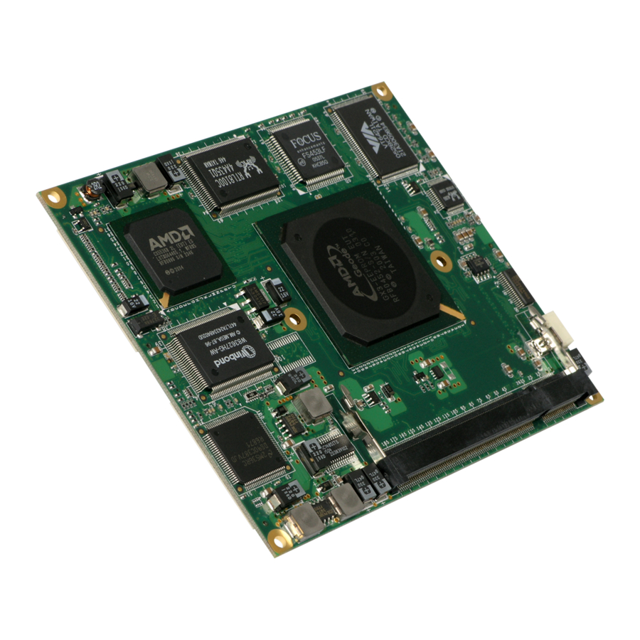
- Page 1 XTX™ conga-XLX AMD Geode ™ LX processors with an AMD Geode ™ CS5536 companion device User's Guide Revision 1.2...
- Page 2 4.1.4 Onboard Generated Supply Voltage. Added note about floppy cable to section 4.3.6 Parallel Port/Floppy Interface. Added section 5.5 'congatec Battery Management Interface'. Added LVDS signal mapping to table 17 LVDS Interface Pinout. Updated section 7 System Resources and section 8 BIOS Setup Description.
- Page 3 AG assumes no liability for any damages incurred directly or indirectly from any technical or typographical errors or omissions contained herein or for discrepancies between the product and the user's guide. In no event shall congatec AG be liable for any incidental, consequential, special, or exemplary damages, whether based on tort, contract or otherwise, arising out of or in connection with this user's guide or any other information contained herein or the use thereof.
- Page 4 Copyright © 2006, congatec AG. All rights reserved. All text, pictures and graphics are protected by copyrights. No copying is permitted without written permission from congatec AG. congatec AG has made every attempt to ensure that the information in this document is accurate yet the information contained within is supplied “as-is”. Trademarks AMD is a trademark of Advanced Micro Devices, Inc.
- Page 5 AG makes no representation, warranty or guaranty, express or implied regarding the products except its standard form of limited warranty ("Limited Warranty"). congatec AG may in its sole discretion modify its Limited Warranty at any time and from time to time.
- Page 6 XTX™ offers the newest I/O technologies on this proven form factor. Now that the ISA bus is being used less and less in modern embedded applications congatec AG offers an array of different features on the X2 connector than those currently found on the ETX ®...
- Page 7 Below you will find an order table showing the different configurations that are currently offered by congatec AG. Check the table for the Part no./Order no. that applies to your product. This will tell you what options described in this user's guide are available on your particular module.
-
Page 8: Table Of Contents
4.3.5 Serial Infrared Interface......................23 4.3.6 Parallel Port/Floppy Interface....................23 4.3.7 Keyboard/Mouse........................24 4.4 Connector X4.......................... 25 4.4.1 IDE............................25 4.4.2 Ethernet..........................25 4.4.3 I²C Bus 400kHz........................25 4.4.4 Power Control........................25 4.4.5 Power Management......................27 Copyright © 2006 congatec AG X800m12 8/72... - Page 9 5.3 Embedded BIOS........................28 5.3.1 Simplified Overview of BIOS Setup Data Backup..............29 5.4 Security Feature........................30 5.5 congatec Battery Management Interface................. 30 6 Signal Descriptions and Pinout Tables..................31 6.1 X1 Connector Signal Descriptions................... 31 6.2 Connector X1 Pinout....................... 34 6.3 X2 Connector Signal Descriptions (XTX™...
- Page 10 9 Additional BIOS Features......................71 9.1 Updating the BIOS........................71 10 Industry Specifications......................72 Copyright © 2006 congatec AG X800m12 10/72...
-
Page 11: Specifications
• • AC'97 Digital Audio Interface PS/2 Keyboard, Mouse • • Based on Insyde XpressROM 1MByte Flash BIOS with congatec Embedded BIOS BIOS features Power Management ACPI 2.0 compliant with battery support. Also supports Suspend to RAM (S3). Note Some of the features mentioned in the above Feature Summary are optional. Check the article number of your module and compare it to the option information list on page 7 of this user's guide to determine what options are available on your particular module. -
Page 12: Supported Operating Systems
• 1.4 Supply Voltage Standard Power Characteristics Units Comment +/-5% 4.75 5.00 5.25 Voltage 0-20MHz Ripple Current See section 1.5 'Power Consumption' for supply current information. +/-5% 4.75 5.00 5.25 5V_SB Voltage Current Copyright © 2006 congatec AG X800m12 12/72... -
Page 13: Supply Voltage Ripple
10 mA is noticed. Each module was measured while running Windows XP Professional with SP2 (service pack 2) and the “Power Scheme” was set to “Portable/Laptop”. The screen resolution Copyright © 2006 congatec AG X800m12 13/72... -
Page 14: Conga-Xlx 500Mhz With 128 Kbyte Cache
Operating System Windows XP Professional SP2 Power State Desktop Idle 100% workload Standby Suspend to Ram (S3) Power consumption (measured 1.3 A/6.5 W 1.7 A/8.5 W 1.1 A/5.5 W 0.2 A/1 W in Amperes/Watts) Copyright © 2006 congatec AG X800m12 14/72... -
Page 15: Supply Voltage Battery Power
If for some reason it is not possible to use the appropriate congatec module heatspreader, then it is the responsibility of the operator to ensure that all components found on the module operate within the component manufacturer's specified temperature range. -
Page 16: Block Diagram
Block Diagram Copyright © 2006 congatec AG X800m12 16/72... -
Page 17: Heatspreader
Application Note AN14_ETX_XTX_Mounting_Solutions.pdf that can be found on the congatec website. Copyright © 2006 congatec AG X800m12 17/72... -
Page 18: Heatspreader Dimensions
3.1 Heatspreader Dimensions Note All measurements are in millimeters. Torque specification for heatspreader screws is 0.5 Nm. Copyright © 2006 congatec AG X800m12 18/72... -
Page 19: Connector Subsystems
Geode™ CS5536 companion device. These controllers comply with USB standard 1.1 and 2.0 and provide a total of four USB ports on the X1 connector that support the connection of USB 2.0 compliant devices. Copyright © 2006 congatec AG X800m12 19/72... -
Page 20: Audio
(3.3V±5%). 3.3V external devices can be connected to these pins but must not exceed a maximum external load of 500mA. For more information about this feature contact congatec AG technical support. Caution Do not connect pins 12, 16 and 24 to a 3.3V external power supply. This will cause a current cross-flow and may result in either a system malfunction and/or damage to the external power supply and the module. -
Page 21: Connector X2 (Xtx™ Extension)
The driver for this controller can be found on the congatec website. There are also special instructions included as a README file within the driver package that explains how to use the hard drive as an OS installation drive for Windows XP and 2000. -
Page 22: Ac'97 Digital Audio
(revolutions per minute). This signal must receive two pulses per revolution in order to produce an accurate reading. For this reason a two pulse per revolution fan, or similar hardware solution, is recommended. These features are implemented by the Winbond W83627HG super I/O. Copyright © 2006 congatec AG X800m12 22/72... -
Page 23: Connector X3
BIOS setup program. See section 8.5.5 of this document for information about configuring the parallel port/floppy interface. Note When using the onboard floppy interface the floppy drive must be connected via a Copyright © 2006 congatec AG X800m12 23/72... -
Page 24: Keyboard/Mouse
The floppy drive will not function when connected via a twisted floppy cable. 4.3.7 Keyboard/Mouse The implementation of these subsystems comply with ETX ® specification 2.7. Copyright © 2006 congatec AG X800m12 24/72... -
Page 25: Connector X4
The driver for the VIA VT6421 can be found on the congatec website. There are also special instructions included as a README file within the driver package that explains how to use the hard drive as an OS installation drive for Windows XP and 2000. - Page 26 It has also been noticed that on some occasions problems occur when using a 5V • power supply that produces non monotonic voltage when powered up. The problem Copyright © 2006 congatec AG X800m12 26/72...
-
Page 27: Power Management
25 figure 7 of the document “ATX12V Power Supply Design Guide V2.2”. 4.4.5 Power Management APM 1.2 compliant. ACPI 2.0 compliant with battery support. Also supports Suspend to RAM (S3). Copyright © 2006 congatec AG X800m12 27/72... -
Page 28: Additional Features
The conga-XLX is equipped with an ATMEL Atmega88 microcontroller. This onboard microcontroller plays an important role for most of the congatec BIOS features. It fully isolates some of the embedded features such as system monitoring or the I²C bus from the x86 core architecture, which results in higher embedded feature performance and more reliability, even when the x86 processor is in a low power mode. -
Page 29: Simplified Overview Of Bios Setup Data Backup
Simplified Overview of BIOS Setup Data Backup The above diagram provides an overview of how the BIOS Setup Data is backed up on conga-XLX. Once the BIOS Setup Program has been entered and the settings have been changed, Copyright © 2006 congatec AG X800m12 29/72... -
Page 30: Security Feature
Exit function continues to perform some minor processing tasks and finally reaches an automatic reset point, which instructs the module to reboot. After the Automatic Reset has been triggered the congatec module can be powered off and, if need be, removed from the baseboard without losing the new CMOS settings. -
Page 31: Signal Descriptions And Pinout Tables
Power Supply +5VDC ±5% External supply Power Ground External supply Power Supply +3.3VDC See section 4.1.4 N.C. Not Connected N.A. Do not connect SERIRQ Serial Interrupt request Used in conjunction with LPC bus Copyright © 2006 congatec AG X800m12 31/72... - Page 32 I 3.3V PU 10k 3.3V Note The PCI bus on the conga-XLX is not 5V tolerant. Caution Connecting 5V PCI devices to the conga-XLX will cause damage to hardware and/or loss of data. Copyright © 2006 congatec AG X800m12 32/72...
- Page 33 Analog input (1 Vrms) Vref (2,5V) ASGND Analog ground of sound controller ASVCC Analog supply of sound controller 5V power output (Can be used as an analog supply for analog amplifier maximum 30mA) Copyright © 2006 congatec AG X800m12 33/72...
-
Page 34: Connector X1 Pinout
AD12 AUXAR AD30 USB1 AD13 ASVCC PCIRST# AD31 AD14 SNDL INTC# INTD# AD15 ASGND INTA# INTB# CBE1# SNDR Note The signals marked with an asterisk symbol (*) are not supported on the conga-XLX. Copyright © 2006 congatec AG X800m12 34/72... -
Page 35: X2 Connector Signal Descriptions (Xtx™ Extension)
Serial ATA channel 3, Transmit Output N.C. Not supported SATA3_TX- differential pair. IL_SATA# Serial ATA Interlock Switch Input. Not supported SATALED# Serial ATA Led. Open collector output pin OC 3.3V driven during SATA command activity. Copyright © 2006 congatec AG X800m12 35/72... - Page 36 Not supported wake signal asserted by components requesting wakeup. Table 11 ExpressCard Support Pins Descriptions Signal Description PU/PD Comment EXEC_CPPE[0..1]# ExpressCard capable card request. N.C. Not supported EXEC_RST[0..1]# ExpressCard Reset N.C. Not supported Copyright © 2006 congatec AG X800m12 36/72...
- Page 37 USBP4# USB Port 4, data - or D- N.C. Not supported USBP5 USB Port 5, data + or D+ N.C. Not supported USBP5# USB Port 5, data - or D- N.C. Not supported Copyright © 2006 congatec AG X800m12 37/72...
- Page 38 Physical Presence to the TPM. Note Some signals have special functionality during the reset process. They may bootstrap some basic important functions of the module. For more information refer to section 6.8 of this user's guide. Copyright © 2006 congatec AG X800m12 38/72...
-
Page 39: X2 Connector Pinout
PCIE1_RX- (*) SATA3_TX- (*) IRQ5 PCIE1_RX+ (*) SATA3_TX+ (*) IRQ6 IL_SATA# (*) IRQ7 PCIE1_TX- (*) PP_TPM SYSCLK PCIE1_TX+ (*) SA10 RESERVED REFSH# PCE_WAKE# (*) SA11 PCI_GNT#A (*) DREQ1 SLP_S5# SA12 PCI_REQ#A (*) DACK1# Copyright © 2006 congatec AG X800m12 39/72... - Page 40 AC_SDIN1 (*) AC_SDIN2 AC_BIT_CLK FAN_TACHOIN NOWS# LPC_AD0 DREQ2 FAN_PWMOUT LPC_AD1 LPC_FRAME# IRQ9 LPC_AD2 LPC_DRQ0# LPC_AD3 IOCHK# LPC_DRQ1# RSTDRV Note The signals marked with an asterisk symbol (*) are not supported on the conga-XLX. Copyright © 2006 congatec AG X800m12 40/72...
-
Page 41: X3 Connector Signal Descriptions
Keyboard Clock O 5V PU 4k7 5V MSDAT Mouse Data I/O 5V PU 4k7 5V MSCLK Mouse Clock O 5V PU 4k7 5V IRTX Infrared Transmit O 5V IRRX Infrared Receive I 5V Copyright © 2006 congatec AG X800m12 41/72... - Page 42 Panel hot-plug detection Not supported FPDDC_CLK DDC lines used for flat panel detection O 3.3V PU 2k2 3.3V and control. FPDDC_DAT DDC lines used for flat panel detection I/O 3.3V PU 2k2 3.3V and control. Copyright © 2006 congatec AG X800m12 42/72...
- Page 43 Line Marker) BIASON N.A. DIGON Controls display Power ON O 5V PD 10k BLON# Controls display Backlight ON O 5V R[0..5], B[0..5], RGB Signals O 3.3V G[0..5] SHFCLK Panel data clock O 3.3V Copyright © 2006 congatec AG X800m12 43/72...
- Page 44 Head select O 5V DIR# Direction O 5V STEP# Motor step O 5V Drive select O 5V MOT# Motor select O 5V WDATA# Raw write data O 5V WGATE# Write enable O 5V Copyright © 2006 congatec AG X800m12 44/72...
- Page 45 Data bus D7 I/O 5V ERR# LPT error I 5V INIT# Initiate O 5V SLIN# Select O 5V ACK# Acknowledge I 5V BUSY Busy I 5V Paper empty I 5V SLCT Power On I 5V Copyright © 2006 congatec AG X800m12 45/72...
- Page 46 CTS2# TXD2 RI2# RXD1 ACK# RTS1# BUSY DTR1# DCD1# SLCT DSR1# MSCLK CTS1# MSDAT TXD1 KBCLK RI1# KBDAT Note The signals marked with an asterisk symbol (*) are not supported on the conga-XLX. Copyright © 2006 congatec AG X800m12 46/72...
-
Page 47: X4 Connector Signal Descriptions
PU 10k 3.3V Note Some signals have special functionality during the reset process. They may bootstrap some basic important functions of the module. For more information refer to section 6.8 of this user's guide. Copyright © 2006 congatec AG X800m12 47/72... - Page 48 I 5V OVCR# Over current detect for USB I 3.3V PU 10k 3.3V ROMKBCS# Do not connect N.A. Not available EXT_PRG Do not connect N.A. Not available GPCS# General purpose chip select Not supported Copyright © 2006 congatec AG X800m12 48/72...
-
Page 49: X4 Connector Pinout
SIDE_INTRQ PIDE_A1 GPE2# CBLID_P# BATLOW# GPE1# RXD# PIDE_D8 SIDE_AK# PIDE_INTRQ SIDE_D7 SIDE_RDY PIDE_AK# TXD# PIDE_D7 SIDE_IOR# PIDE_RDY HDRST# Note The signals marked with an asterisk symbol (*) are not supported on the conga-XLX. Copyright © 2006 congatec AG X800m12 49/72... -
Page 50: Boot Strap Signals
If it is necessary to drive a TTL input (or another input which sources or sinks significant current) that uses the TXD1 signal, a CMOS-input buffer can be inserted in the signal path so that this line is not pulled up or down by external circuitry during system reset. Copyright © 2006 congatec AG X800m12 50/72... -
Page 51: System Resources
** Only if ACPI Aware OS is set to YES in setup. *** The UMA area from C8000h – DFFFFh will only be available if Network Boot Support and External HDD Boot Support are not used. Copyright © 2006 congatec AG X800m12 51/72... -
Page 52: I/O Address Assignment
DD80 - DEFF 384bytes Audio controller registers DEA0 - DFFF 96 bytes RAID controller registers EFF0 – EFFF 16 bytes IDE controller registers Notes Default, but can be changed to another address range. Copyright © 2006 congatec AG X800m12 52/72... -
Page 53: Interrupt Request (Irq) Lines
Notes 1. Default, but can be changed to another interrupt. 2. In ACPI mode, IRQ9 is used for the SCI (System Control Interrupt). The SCI can be shared with a PCI interrupt line. Copyright © 2006 congatec AG X800m12 53/72... -
Page 54: Direct Memory Access (Dma) Channels
VT6421 RAID Controller Internal ISA Bridge Internal IDE Controller Internal Audio Multimedia Device Internal OHCI Host Controller 0 Internal OHCI Host Controller 1 Internal UDC Controller Internal ODC Controller INTD RTL8100C Ethernet Controller Copyright © 2006 congatec AG X800m12 54/72... -
Page 55: Pci Interrupt Routing Map
System Management (SM) bus signals are connected to the AMD Geode™ CS5536 companion device and the SM bus is not intended to be used by off-board non-system management devices. For more information about this subject contact congatec technical support. 7.10 LPC Bus Low Pin Count bus signals are connected to the AMD Geode™... -
Page 56: Bios Setup Description
This is helpful when a previous BIOS setting is no longer desired. 8.2 Setup Menu and Navigation The congatec BIOS setup screen is composed of main frames, with submenu selections. The main frame displays all the options that can be configured in the selected menu. -
Page 57: Main Menu
Displays the hardware revision of the board. Serial Number no option Displays the serial number of the board. BC Firmware Rev. no option Displays the revision of the congatec board controller. Boot Counter no option Displays the number of boot-ups (max. 16777215). Running Time no option Displays the time the board is running [in h] (max. -
Page 58: Device Configuration
F. USB Configuration Set the USB configuration G. Watchdog Configuration Set the watchdog configuration H. Hardware Monitoring Monitors the system temperature, voltages and the fan speed I. Boot Screen Configuration Set the boot screen configuration Copyright © 2006 congatec AG X800m12 58/72... -
Page 59: Drive Configuration Submenu
The driver for this controller can be found on the congatec website. There are also special instructions included as a README file within the driver package that explains how to use a hard drive that is attached to this controller as an OS installation drive for Windows XP and 2000. -
Page 60: Graphics Configuration Submenu
Enables/Disables only the L2 system cache. Disabled Cache Mode Select the cache mode write-back or write-through. Write-Back Write Through Cache Allocate Enabled Select if a cache line should be allocated before write. Disabled Copyright © 2006 congatec AG X800m12 60/72... -
Page 61: Pci Configuration Submenu
PCI INTD# 3, 4, 5, 7, 9, 10, 11, Select fixed IRQ for PCI interrupt line. Note: Make sure that the selected IRQ is not assigned to a legacy I/O. 12, 14, 15 Copyright © 2006 congatec AG X800m12 61/72... -
Page 62: I/O Interface Configuration Submenu
Specifies the DMA channel for the parallel port in ECP mode. None DMA1 DMA3 External Super I/O Submenu for external Super I/O configuration. Submenu Configuration Menu Note: This submenu is only selectable if a external Winbond W83627HG Super I/O is present. Copyright © 2006 congatec AG X800m12 62/72... -
Page 63: External Super I/O Configuration Submenu
This submenu is only available if an external Winbond W83627HG Super I/O controller is present in the system. The configuration base I/O address of the Super I/O has to be 0x4E and 0x4F. Copyright © 2006 congatec AG X800m12 63/72... -
Page 64: Usb Configuration Submenu
Enables/Disables legacy USB support for keyboard/mouse emulation and legacy USB boot support. Disabled Note: If legacy USB support is disabled, it is not possible to enter the system Setup program with USB keyboard. Copyright © 2006 congatec AG X800m12 64/72... -
Page 65: Watchdog Configuration Submenu
5sec 10sec 30sec 1min 2min Timeout 2 see above Selects the timeout value for the second stage watchdog event. Timeout 3 see above Selects the timeout value for the third stage watchdog event. Copyright © 2006 congatec AG X800m12 65/72... -
Page 66: Hardware Monitoring Submenu
0 - 65535 ROM initialization. Summary Screen Disabled Enable/Disable the summary screen during bootup. Enabled Summary Screen Timeout 0 - 65535 Determines the time, the summary screen is displayed before booting any OS. Copyright © 2006 congatec AG X800m12 66/72... -
Page 67: Performance Control
500 MHz Note congatec strongly recommends that when using the 'Manual Settings' option the 'CPU Clock Speed' should be set to the default value, which is 500MHz. If an alternative setting for the 'CPU Clock Speed' must be used then it's recommended that this setting be extensively evaluated in conjunction with the complete system. -
Page 68: Power Management
In ACPI mode it is not possible for a “Watchdog ACPI Event” handler to directly restart or shutdown the OS. For this reason the congatec BIOS will do one of the following: For Shutdown: An over temperature notification is executed. This causes the OS to shut down in an orderly fashion. - Page 69 1. The term 'AC power loss' stands for the state when the module looses the standby voltage on the 5V_SB pins. On congatec modules, the standby voltage is continuously monitored after the system is turned off. If within 30 seconds the standby voltage is no longer detected, then this is considered an AC power loss condition.
-
Page 70: Boot Device Priority
Usually another AC power off/on cycle is necessary to recover from this situation. 3. Unlike other module designs available in the embedded market, a CMOS battery is not required by congatec modules to support the 'Power Loss Control' feature. 8.8 Boot Device Priority Feature... - Page 71 BIOS project name and a revision code. The initial production BIOS is identified as X800R115, where X800 is the congatec internal project name, R is the identifier for a BIOS ROM file, 1 is the so called feature number and 10 is the major and minor revision number.
- Page 72 10 Industry Specifications The list below provides links to industry specifications that apply to congatec AG modules. Specification Link Audio Codec ‘97 Component Specification, Version 2.3 http://www.intel.com/design/chipsets/audio/ (AC ’97) Low Pin Count Interface Specification, Revision 1.0 (LPC) http://developer.intel.com/design/chipsets/industry/lpc.htm Universal Serial Bus (USB) Specification, Revision 2.0 http://www.usb.org/home...
Need help?
Do you have a question about the XTX conga-XLX and is the answer not in the manual?
Questions and answers