Table of Contents
Advertisement
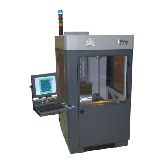
User's Manual
™
iPro
8000 SLA
™
iPro
9000 SLA
40-D043 – Rev C
Copyright © 2017 by 3D Systems Corporation. All rights reserved. SLA and the 3D logo are registered trademarks of 3D Systems, Inc. and
3D Sprint, 3DPrint, 3DManage, Lightyear, ProCure, Viper, iPro and Zephyr are trademarks of 3D Systems, Inc.
Cover Page
®
Center
®
Center
Advertisement
Table of Contents

Related Manuals for 3D Systems iPro 8000 SLA Center


Summary of Contents for 3D Systems iPro 8000 SLA Center
- Page 1 40-D043 – Rev C Copyright © 2017 by 3D Systems Corporation. All rights reserved. SLA and the 3D logo are registered trademarks of 3D Systems, Inc. and 3D Sprint, 3DPrint, 3DManage, Lightyear, ProCure, Viper, iPro and Zephyr are trademarks of 3D Systems, Inc.
-
Page 2: Table Of Contents
8000/9000 User’s Manual Thank you for purchasing the iPro™ 8000 SLA ® Center. Before using this equipment, please read this guide carefully to enjoy optimum performance and longer service life. Table of Contents Introduction History What’s Inside? Machine Window iPro SLA System’s Features - RDM Build Window Other Useful Documents Mechanical Process... - Page 3 Stereolithography - From stereo, for three-dimensional, and lithography, for printing, stereolithography is literally three-dimensional printing. It is the term used to describe 3D Systems’ patented fabrication process that “prints” three-dimensional, solid objects by solidifying liquid plastic using a computer-directed, ultraviolet (UV) laser beam to cure successive layers of photo-sensitive polymer resin in an RDM (Resin Delivery Module).
- Page 4 I n t r o d u c t i o n 8000/9000 User’s Manual What’s the difference? The numerous build configurations available from the two iPro systems featured in this manual offer a broad range of options to produce high-definition plastic parts with unmatched quality and accuracy.
-
Page 5: What's Inside
W h a t ’s i n s i d e ? 8000/9000 User’s Manual What’s Inside? This manual includes the following topics: Latest Features “iPro SLA Center’s Features” describes the latest features incorporated into the iPro 8000/9000 SLA Center, such as the resin delivery module (RDM), Intelligent Resin Container, Recoater, and Scanning System. - Page 6 W h a t ’s i n s i d e ? 8000/9000 User’s Manual Recoater System “Recoater System” describes how to perform different operations with the resin delivery module (RDM). Safety “General “Laser “Chemical Safety”, and “Environmental Conditions” describe Safety”, Safety”, precautions that you should take when using your new iPro 8000/9000 SLA Center.
- Page 7 F e a t u r e s 8000/9000 User’s Manual iPro 8000/9000 SLA Center’s Features Resin Delivery Module (RDM) The RDM is a vital system component. It is the mobile container that stores the resin material and is rolled into the iPro™ SLA® Center to build parts.
- Page 8 The iPro 9000 XL builds large, single-piece parts up to 60-inches long with all of the performance attributes and accuracy that users have come to expect from 3D Systems' high-definition Stereolithography process. This system delivers extra-large parts with no seams for aesthetic superiority, one-piece durability, resulting in reduced labor and decreased cost.
- Page 9 F e a t u r e s 8000/9000 User’s Manual There are two operating modes for the RDM: Stand-by Mode In this mode, the RDM is offline and operates independently from the iPro 8000/9000 SLA Center, permitting offline resin and module temperature stabilization when it is connected with line power to the power umbilical.
- Page 10 F e a t u r e s 8000/9000 User’s Manual Single Resin Delivery Module The iPro 8000/9000 SLA Center builds with one resin delivery module, focusing on speed and accuracy, without compromising space requirements. Dual Resin Delivery Module The iPro 9000 SLA Center can also build parts in two separate build zones, Build Zone A and Build Zone B.
- Page 11 F e a t u r e s 8000/9000 User’s Manual Recoating Module The recoater system has a Zephyr ™ recoater blade with four axes of motion: The y-axis moves the recoater blade front to rear; the z-axis moves it up and down; the theta y-axis tips or rotates the blade about the center;...
-
Page 12: Other Useful Documents
O t h e r U s e f u l D o c u m e n t s 8000/9000 User’s Manual Other Useful Documents The following documents will help you to achieve maximum proficiency with your iPro 8000/9000 SLA Center. - Page 13 O t h e r U s e f u l D o c u m e n t s 8000/9000 User’s Manual iPro 8000/9000 SLA Center Material Safety Data Sheets (MSDSs) Make sure that everyone in your facility who handles iPro 8000/9000 SLA Center materials reads these MSDSs and follows the safety guidelines in them.
-
Page 14: General Safety
G e n e r a l S a f e t y 8000/9000 User’s Manual General Safety Hazard Messages There are four safety hazard messages in this iPro 8000/9000 SLA Center User’s Manual: Also “Safety Labels” for descriptions of safety labels on your iPro 8000/9000 SLA Center. Damage Machine damage, part damage, and/or data loss can result if you ignore this type of hazard message. - Page 15 • Operators are trained to operate the system and to perform all the necessary tasks to build a part. • Certified service personnel have completed the 3D Systems service training package and are certified to perform service tasks. Certification may occur at various levels and servicers should only perform tasks that they are authorized and certified to complete.
- Page 16 G e n e r a l S a f e t y 8000/9000 User’s Manual • If you see an error message on the system’s display, refer to Troubleshooting before resuming operation. • To prevent potential skin irritation and sensitization due to contact with waste material, follow all guidelines in the iPro 8000/9000 SLA Center Material Handling Safety Material Disposal...
-
Page 17: Laser Safety
L a s e r S a f e t y 8000/9000 User’s Manual Laser Safety The SLA Center is designated as a Class I Laser Device by the U.S. Center for Devices and Radiological Health (CDRH). Class I devices are not considered harmful and require no special safety precautions. - Page 18 L a s e r S a f e t y 8000/9000 User’s Manual Radiation During normal operation, and with all panels installed, the iPro 8000/9000 SLA Center is classified as a Class I laser device. If any of the interlocks are defeated, the iPro 8000/9000 SLA Center becomes a Class IV device.
- Page 19 L a s e r S a f e t y 8000/9000 User’s Manual Emergency Shut-off All SLA Centers have an Emergency Shut-off button on the front panel of the Control Module/ Bay. The iPro 8000/9000 SLA Center has an additional Emergency Shut-off button inside the Process Chamber.
- Page 20 L a s e r S a f e t y 8000/9000 User’s Manual Safety Warning Labels Laser safety warning labels for the iPro 8000/9000 SLA Centers are affixed inside the process module and RDM. On the iPro 8000/9000 SLA Center, labels are affixed on the frame behind the RDM door and near the aperture at the top of the process chamber.
- Page 21 L a s e r S a f e t y 8000/9000 User’s Manual Safety Labels Safety labels are attached & Interlocks at the places shown. Safety Label (in frame behind the door) Safety Safety Label Label An interlock is located Bypass close to each label.
-
Page 22: Chemical Safety
C h e m i c a l S a f e t y 8000/9000 User’s Manual Chemical Safety Irritant! Always wear chemical-resistant gloves, goggles, and protective clothing when handling resin. Avoid skin contact. Avoid breathing resin fumes. • Always wear approved goggles, nitrile gloves and protective clothing when working near resins or with partially cured parts. - Page 23 Consult the manufacturer’s Material Safety Data Sheet (MSDS) for information on specific resins. For further information on this and related 3D Systems – Materials topics, consult the website. Resin Storage Resin should be stored in opaque, non-reactive containers, according to the guidelines given in the MSDS included with the resin.
- Page 24 C h e m i c a l S a f e t y 8000/9000 User’s Manual Caution! Resin is combustible. Care should be taken during resin containment and cleanup operations. A supply of dikes and control booms should be stocked so they are available to contain the affected area in the event of a major resin spill.
- Page 25 C h e m i c a l S a f e t y 8000/9000 User’s Manual Eye Contact Safety goggles should be worn to prevent accidental splashes into the eyes. If resin comes in contact with the eye, flush immediately with large amounts of water for 15 minutes, avoid sunlight, fluorescent light, and other ultraviolet light, and obtain immediate medical attention.
-
Page 26: Environmental Conditions
E n v i r o n m e n t a l C o n d i t i o n s 8000/9000 User’s Manual Environmental Conditions Temperature To allow optimum systems operation and optimum part quality, the temperature of the iPro 8000/9000 SLA System’s room or other location should remain stable. -
Page 27: Operations
O p e r a t i o n s 8000/9000 User’s Manual Operations iPro 8000/9000 SLA Center System System Status Lights Status Lights User User Interface Interface Build Zone Build Zone A Electrical Build Zone B Electrical Cabinet Cabinet IPM: The iPro 8000/9000 SLA IPM (Image Projection Module) relays the drawing into information that will enable a build. - Page 28 O p e r a t i o n s 8000/9000 User’s Manual User Interface: The user interface enables you to program the criteria for the build, using 3D Print software. Build Zone A: Build Zone A is the left side of the iPro 8000/9000 SLA Center, as you face the Machine, and is utilized for the building of all machine configurations.
- Page 29 O p e r a t i o n s 8000/9000 User’s Manual User Interface Monitor (rear): Power & Monitor Adjustments Emergency Stop Chamber Light Laser On System Enable System Secure Bypass Key Keyboard Monitor: The monitor, located above the keyboard, shows you the status of the build and the software required to start and complete the build.
- Page 30 O p e r a t i o n s 8000/9000 User’s Manual Chamber Light: This switch turns the chamber lighting on or off. System Enable: This switch enables the system once the operational software has been launched. It also re-enables the system following an emergency stop, which occurs after the emergency stop switch returns to the open state.
- Page 31 O p e r a t i o n s 8000/9000 User’s Manual Resin Delivery Module (RDM) Refill Container 1 Refill Container 2 Leveling Container Blade Rest I/O Connector RDM Heater Power Switch Valve Assembly Gross Fill / Circulation Pump Leveling Pump 40-D043 Revision C 5-May-17 www.3dsystems.com...
- Page 32 O p e r a t i o n s 8000/9000 User’s Manual Refill Container 1 and 2: These removable containers store new resin, which is added to the RDM as needed, prior to the start of a build. Blade Rest: The blade rest area is used to stow the removable recoater blade when changing RDMs.
- Page 33 O p e r a t i o n s 8000/9000 User’s Manual Electrical Cabinet Main Power Disconnect Electrical Cabinet: Closed Door Main Power Disconnect: The disconnect enables you to turn off all power to the system. Do NOT position the equipment so that it is difficult to operate the disconnecting device. 40-D043 Revision C 5-May-17 www.3dsystems.com...
- Page 34 O p e r a t i o n s 8000/9000 User’s Manual Laser Power Supply Controller Power Distribution Electrical Cabinet: Open Door Laser Power Supply: The laser power supply enables the user to turn on and off the power. 40-D043 Revision C 5-May-17 www.3dsystems.com...
- Page 35 O p e r a t i o n s 8000/9000 User’s Manual Controller: The computer operates the iPro 8000/9000 SLA Center. Power Distribution: This module distributes all the AC power that the systems need. Circuits for the various subsystems are located in this module. Laser Cooling System: The laser cooling system maintains the optimum laser head temperature.
- Page 36 O p e r a t i o n s 8000/9000 User’s Manual Manual Offload Cart The manual offload cart is available as an option when you purchase an iPro™ SLA® Center. You can easily remove a platform from the SLA Center with a large or heavy part on it. This cart moves the platform and parts to the finishing area, where supports are removed and the part is cleaned before it is cured.
-
Page 37: Software Overview
User’s Manual 3D Sprint 2.5 Software Overview 2.5 is the 3D Systems’ software application used for preparing CAD models to be printed on an SLA 3D SPRINT printer. It is installed on a standalone computer which is provided by the customer. Double-click the 3D SPRINT icon on your computer/laptop, or select it from your list of available programs loaded on your computer. - Page 38 S o f t w a r e O v e r v i e w 8000/9000 User’s Manual 3DPrint Software Overview 3DPrint is legacy software for the iPro 8000/9000. If you are still using 3DPrint , please consider upgrading your computer for the new 3D Sprint software.
-
Page 39: View Port And View Object
V i e w P o r t a n d V i e w O b j e c t 8000/9000 User’s Manual View Port and View Object When the view port is the active window, the user can see the build in progress. The build envelope is the maximum space for part building. - Page 40 V i e w P o r t a n d V i e w O b j e c t 8000/9000 User’s Manual Viewing Controls Pre-Defined View Angles Rendering Style Rotate Around X-axis Rotate Around Y-axis Rotate Around Z-axis Zoom Out Rotate Around X-axis Zoom In...
- Page 41 V i e w P o r t a n d V i e w O b j e c t 8000/9000 User’s Manual Mouse and Keyboard To perform the following commands via mouse and keyboard: Translate View Port: Alt + Right Mouse + Drag Zoom View Port: Shift + Right Mouse Button + Drag 40-D043 Revision C 5-May-17...
-
Page 42: Menu Bar
M e n u B a r 8000/9000 User’s Manual Menu Bar File New: Clears current build file. Rebuild: Reloads the last build file. Open: Selects a new build file; prompts user to clear the current file, if current file is not closed. Close: Closes the current build file. - Page 43 M e n u B a r 8000/9000 User’s Manual Preferences Edit Defaults: Edits the 3DPrint XML file. Save Defaults: Writes out, or saves, the 3DPrint XML file. Load Defaults: Loads the 3DPrint XML file. Reset Defaults: Resets the 3DPrint XML file. Preferences enables you to edit, save, load, and reset defaults.
- Page 44 M e n u B a r 8000/9000 User’s Manual Licensing Load License: For initial software run only, enables user to load license and activate application; user must load license to use application Get Host ID: Obtains ID of the computer user and places it in a text file 40-D043 Revision C 5-May-17 www.3dsystems.com...
- Page 45 M e n u B a r 8000/9000 User’s Manual Edit The Edit menu enables you to Cut, Copy, Paste, Undo, and Redo. 40-D043 Revision C 5-May-17 www.3dsystems.com...
- Page 46 M e n u B a r 8000/9000 User’s Manual Display Build Volume: Toggles the display of the build volume. Build Plane: Shows the z-height status of the part build during a build. Build Layer: Displays image of the layer currently being built during a build. The Display menu enables you to choose Build Volume, Build Plane, or Build Layer.
- Page 47 M e n u B a r 8000/9000 User’s Manual View The View menu currently has no function. 40-D043 Revision C 5-May-17 www.3dsystems.com...
- Page 48 M e n u B a r 8000/9000 User’s Manual Setup The Setup menu enables you to interact with the \\Your folder\Bff\ systems hardware through the use of the Manual and Scanner windows: Manual: Opens the manual operations window; see Manual Operations.
- Page 49 M e n u B a r 8000/9000 User’s Manual Window Reset Panels: Goes back to the panel that was saved Default Panels: Goes back to the factory setting Save Panels: Saves current panel setting Auto Save Panels: When this box is checked, panel settings are automatically saved at the application’s exit.
- Page 50 M e n u B a r 8000/9000 User’s Manual Help The Help menu gives you information about the 3DPrint software release. 40-D043 Revision C 5-May-17 www.3dsystems.com...
-
Page 51: Tool Bar
T o o l B a r 8000/9000 User’s Manual Tool Bar Status: Shows machine status. Queue: Lists the build jobs in the queue. Open: Browse for a new build file; prompts you to clear the current file if one is currently open. Play: Starts the build. -
Page 52: Manual Operations
M a n u a l O p e r a t i o n s 8000/9000 User’s Manual Manual Operations Manual Operations, explained in more detail on the following pages, enables the user to make manual adjustments regarding the elevator, recoater, and leveler. 40-D043 Revision C 5-May-17 www.3dsystems.com... - Page 53 Enable Crash Protection Use extreme caution when moving motion axes if is unchecked. Damage caused by this type of collision is not covered under the 3D Systems’ warranty. 40-D043 Revision C 5-May-17 www.3dsystems.com...
- Page 54 M a n u a l O p e r a t i o n s 8000/9000 User’s Manual Elevator The manual operations Elevator allows you to operate the elevator manually. “Machine Window”, and the following textual explanations, show the command’s functions. Be careful when entering values;...
- Page 55 M a n u a l O p e r a t i o n s 8000/9000 User’s Manual Note: These values apply only to manual movement. Move: Manually moves elevator as the user specifies. Distance: Specifies distance, in inches or millimeters, from current position; negative moves elevator down, positive moves elevator up.
- Page 56 M a n u a l O p e r a t i o n s 8000/9000 User’s Manual Note: These functions will not work if elevator has not been homed. Start: Moves the elevator to its Start position, as defined by Set Start. Set Start: Saves the elevator’s current location as the Start position;...
- Page 57 M a n u a l O p e r a t i o n s 8000/9000 User’s Manual Recoater The manual Recoater allows you to operate the recoater manually. The following pages show the command’s functions. To Move the Recoater forward or back, specify Distance and Velocity.
- Page 58 M a n u a l O p e r a t i o n s 8000/9000 User’s Manual Move: Manually moves recoater as the user specifies. Distance: Specifies distance, in inches or millimeters, from current position; negative moves recoater toward the front of the machine, positive moves recoater toward the rear of the machine.
- Page 59 M a n u a l O p e r a t i o n s 8000/9000 User’s Manual Leveler The manual Leveler controls the resin level in the RDM through the use of the gross fill and leveling pumps on the front of the RDM. It also allows for the resin to recirculate. To Move the resin level by a set distance,...
- Page 60 M a n u a l O p e r a t i o n s 8000/9000 User’s Manual Turns: Defines the amount of resin to be pumped; negative pumps resin into the RDM from the leveling container; positive pumps resin out of the RDM into the leveling container. Velocity: Specifies the pump speed in revolutions per second.
- Page 61 S c a n n e r 8000/9000 User’s Manual Scanner Scanner, explained in more detail on the following pages, enables the user to make manual adjustments regarding the Laser, Scanner, and Sensors. 40-D043 Revision C 5-May-17 www.3dsystems.com...
- Page 62 S c a n n e r 8000/9000 User’s Manual Laser Laser On: Toggles the laser on or off, by either check (on) or uncheck (off). Shutter: Toggles safety shutter open or closed, by either check (open) or uncheck (closed). Small Spot: Sets IPM to the small spot focus position.
- Page 63 S c a n n e r 8000/9000 User’s Manual Scanner Moves beam in the positive Y direction Moves beam in the negative X direction Moves beam in the positive X direction Moves beam in the negative Y direction Moves the beam to the home (rest) position. Moves the beam to the center of the build chamber.
- Page 64 S c a n n e r 8000/9000 User’s Manual Distance: Defines the distance increment when moving the beam with the arrow buttons. To move the beam faster, use a larger value; for finer movement, use a smaller value. Note: Moving the beam to reach the scanner limit will result in a fatal error. This will require the system to be restarted.
- Page 65 S c a n n e r 8000/9000 User’s Manual Sensors Sensor 1: Sensor 1 settings are the same as sensor 2. Note: Sensor 1 is not used in a single or dual RDM hardware configuration, therefore, the default values may not be defined.
- Page 66 S c a n n e r 8000/9000 User’s Manual Find: Searches for a pin hole, starting at the current beam position. Profile: Acquires and displays the power distribution and properties of the beam. ADC: Shows the current intensity of the beam. X Location: Shows the X coordinate of the beam.
-
Page 67: History
H i s t o r y 8000/9000 User’s Manual History Build Log Window History displays information about previous builds. Clicking on History brings up the Build Log window, which contains the information about the last build. If build is in progress, Open and Last are disabled. - Page 68 H i s t o r y 8000/9000 User’s Manual Open Build Log Window Clicking Open displays the list of all previous builds. Selecting a file, or build, displays the information on that particular build. Clicking Last displays the information of the last build. Clicking Done closes the Build Log window.
-
Page 69: Machine Window
M a c h i n e W i n d o w 8000/9000 User’s Manual Machine Window Status Status enables you to display the properties of the resin delivery module (RDM), as well as the available laser power. Resin: Displays the resin name. - Page 70 M a c h i n e W i n d o w 8000/9000 User’s Manual Settings Settings enables you to view/change the machine settings. Name: Displays the resin. Air Temp: Selects air temperature in degrees C. RDM Temp: Selects the resin temperature in degrees C. Alarm Temp: Selects the temperature at which the RDM heater shuts off to prevent overheating.
- Page 71 M a c h i n e W i n d o w 8000/9000 User’s Manual Options enables you to select or deselect the machine options for the Options build. Checking the boxes selects the following options: Skip Init: Skips the initial operations of the build, including coarse resin leveling and proper elevator positioning.
- Page 72 M a c h i n e W i n d o w 8000/9000 User’s Manual Scale Scale enables you to set the X, Y, and Z scale factors of your build. The default value for these settings is 1.0000. Sets the X coordinate Sets the Y coordinate Sets the Z coordinate...
-
Page 73: Build Window
B u i l d W i n d o w 8000/9000 User’s Manual Build Window Build Status Dropdown Status End Build Value Current Status Start Build Value Status shows specific information on the build, as it progresses. The End of Build, Current Build, and Start of Build fields show data at various stages of the build. - Page 74 B u i l d W i n d o w 8000/9000 User’s Manual The Build Status dropdown enables you to change the units of the status of the build. --- units can be in inches for Position. --- percentage for Percent --- hours, minutes, and seconds for Duration and Time (clock).
- Page 75 B u i l d W i n d o w 8000/9000 User’s Manual Settings Start Z: Enables the user to choose the Z location of the build file, where the build will start; if the Start Z value entered is less than the minimum Z extent, the build starts at the minimum;...
- Page 76 B u i l d W i n d o w 8000/9000 User’s Manual Offset Build Offset enables you to shift the location, in the X and Y direction, of the build on the platform. This is used to center the calibration on the platform.
- Page 77 B u i l d W i n d o w 8000/9000 User’s Manual Scale Build Scale enables you to scale the current build in the X, Y, and Z direction. Note: Build Scale Factors and Machine Scale Factors are added together to achieve the final build scale. Example: Build Scale Machine Scale...
- Page 78 B u i l d W i n d o w 8000/9000 User’s Manual Recoat Build Recoat displays the recoat parameter values as defined when the build file was created by the 3DManage™ Software. Distance: Displays elevator dip distance in units (inch/mm) defined by the .bff file.
- Page 79 B u i l d W i n d o w 8000/9000 User’s Manual Modify: This function opens another window. This allows the user to select a recoating range and modify the values. Note: To change this parameter during the build: stop the build, update the setting, and restart the build.
- Page 80 B u i l d W i n d o w 8000/9000 User’s Manual Draw Build Draw displays the most recent, or current, values for laser power and vector drawing speeds. 40-D043 Revision C 5-May-17 www.3dsystems.com...
- Page 81 P a r t s L i s t W i n d o w 8000/9000 User’s Manual Parts List Window The Check box marked with a check indicates that the part listed is visible to the user. The Highlighted Part Name indicates the part is selected. The Parts List gives the contents of the build file.
-
Page 82: Mechanical Process
R e c o a t e r S y s t e m 8000/9000 User’s Manual Mechanical Process Blade Installation and Removal Recoater Blades The recoater blade is on a rail system above the resin delivery module (RDM). The recoating process combines elevator and recoater blade movements to apply liquid resin to the top of the part so that the next layer can be built. - Page 83 R e c o a t e r S y s t e m 8000/9000 User’s Manual Platform Installation The RDM must be in the machine before this process starts. When correctly installed, the platform sits on the elevator platform mount. 1.
- Page 84 R e c o a t e r S y s t e m 8000/9000 User’s Manual Platform Release After the build is complete, select Drain Platform. This function raises the elevator motion stage to the top and the locking mechanism disengages.
- Page 85 R e c o a t e r S y s t e m 8000/9000 User’s Manual Resin Delivery Module (RDM) Installation Make sure that the elevator is at its lower limit and that the recoater module is in the rest position. Assuming the RDM is outside the iPro 8000/9000 SLA Center, the following steps describe how to install it.
- Page 86 R e c o a t e r S y s t e m 8000/9000 User’s Manual 5. Once the RDM is in the machine, connect the cables. There is a black power cord and a gray cable bundle. Plug the three-pronged black power cord into the IEC receptacle on the RDM and place the connector into the keys.
- Page 87 R e c o a t e r S y s t e m 8000/9000 User’s Manual 6. Plug in the power cord and turn on the switch. RDM Heater Power Switch 7. Close the RDM door. Note: See the following page for the additional step necessary for the RDM650. 40-D043 Revision C 5-May-17 www.3dsystems.com...
- Page 88 R e c o a t e r S y s t e m 8000/9000 User’s Manual To use the RDM650, the iPro™ machine must have the rotary switch shown below installed. Some iPro™ machines upgraded from Viper Pro™ may not have the limit sensor switch. Please verify that this switch is on your machine before using the RDM650.
- Page 89 R e c o a t e r S y s t e m 8000/9000 User’s Manual RDM Removal The RDM is made of stainless steel and has casters for moving and maneuvering it while installing or removing it from the frame. There are also handles on the RDM that help to transport and maneuver it into and out of the iPro 8000/9000 SLA Center.
- Page 90 R e c o a t e r S y s t e m 8000/9000 User’s Manual Resin Delivery Module Temperature Control The iPro 8000/9000 SLA Center offers offline and online heating. When the power cord from the machine is connected, the system has online heating; when the power from a wall outlet is connected, the system has offline heating.
- Page 91 R e c o a t e r S y s t e m 8000/9000 User’s Manual Release Lever Release Lever 3. Pull the RDM release lever, located to the left of the resin bin toward you. 40-D043 Revision C 5-May-17 www.3dsystems.com...
- Page 92 R e c o a t e r S y s t e m 8000/9000 User’s Manual Container Release Button 4. Push the container release button, located on the lower right corner of the resin bin. Container Release Button 5. Lift out the resin container. 6.
- Page 93 R e c o a t e r S y s t e m 8000/9000 User’s Manual Resin Containers Before adding a new container, make sure that the container slot is empty. If a container is present, refer to the previous section, “Resin Container Removal,”...
- Page 94 R e c o a t e r S y s t e m 8000/9000 User’s Manual 1. Open the RDM door. 2. Obtain the resin container that is compatible with the resin that is in the RDM. Caution! Make sure that you have selected the correct resin container. Selecting a container that is incompatible with the resin type in the RDM can damage the machine.
-
Page 95: Troubleshooting
T r o u b l e s h o o t i n g 8000/9000 User’s Manual Troubleshooting Power Outages If you are present when a power outage occurs, or if you discover that the main power is off, complete the following steps: 1. - Page 96 T r o u b l e s h o o t i n g 8000/9000 User’s Manual Table 3: Error Symptoms SYMPTOM CAUSE ACTION Controller does Breaker on DC power Reset breaker. not operate. supply is tripped. Check the plugs and cables to ensure that they are Loose cables or poor tightly connected and that the electrical outlet is connection exists at the...
- Page 97 T r o u b l e s h o o t i n g 8000/9000 User’s Manual Table 3: Error Symptoms (continued) SYMPTOM CAUSE ACTION The laser does The laser is not turned Turn the power supply key to the ON position. Verify not operate.
-
Page 98: Customer Support
C u s t o m e r S u p p o r t 8000/9000 User’s Manual Customer Support If you receive an unrecoverable error message, or if you need to contact us for another problem, you may contact our Customer Support Hotline. Before you call Customer Support with a problem or question, please make sure that you have the following information: •... -
Page 99: Service
• In the United States or Canada, call 800-793-3669 • In Europe, call +49-6151-357357 You can also contact your local 3D Systems representative. For material safety data sheets and other technical support information, go to this 3D Systems’ Web site address: http://www.3dsystems.com/techsupport/index.asp... - Page 100 S e r v i c e 8000/9000 User’s Manual The SLA Center conforms to applicable requirements of 21 CFR Subchapter J at the date of manufacture. It is designated a Class I Laser Device by the Center for Devices and Radiological Health (CDRH).
-
Page 101: Maintenance
Remove dust from the outer surfaces of the iPro 8000/9000 SLA Center by wiping with a clean, dry, lint-free cloth. Damage Do not remove any outer panels when cleaning the iPro 8000/9000 SLA Center. Panels must be removed only by a qualified 3D Systems Customer Support Representative. 40-D043 Revision C 5-May-17 www.3dsystems.com... - Page 102 Preventive Maintenance Your iPro 8000/9000 SLA Center must have preventive maintenance (PM) performed by a qualified 3D Systems Customer Support Representative. Contact 3D Systems after one year of build time. Gel Filtering Resin life is adversely affected by partially-polymerized material in the RDM, both in debris, such as broken supports and crash remains, and in gel.
- Page 103 M a i n t e n a n c e 8000/9000 User’s Manual Damage Do not leave debris in the machine and do not allow debris to bypass the debris- catching device. Gel must be kept apart from its neighboring gel, which requires continuous resin movement in the RDM.
-
Page 104: System Block Diagram
S y s t e m B l o c k D i a g r a m 8000/9000 User’s Manual System Block Diagram (single build area) 40-D043 Revision C 5-May-17 www.3dsystems.com... -
Page 105: Electronic Chassis Diagram
E l e c t r o n i c C h a s s i s D i a g r a m 8000/9000 User’s Manual Electronic Chassis Diagram 40-D043 Revision C 5-May-17 www.3dsystems.com... -
Page 106: Legal Notices
Copyright 3D Systems, Inc. All rights reserved. Subject to change without notice. This document is copyrighted and is the property of 3D Systems, Inc. The licensed user, in the name of whom this document is registered (the “Licensed User”) does not have the right to copy, reproduce, or translate this document in any way or to any media without the prior written consent of 3D Systems, Inc. - Page 107 Operation of this equipment in a residential area is likely to cause harmful interference in which case, the user will be required to correct the interference at his own expense. Changes or modifications not expressly approved by 3D Systems could void your authority to operate equipment.
-
Page 108: Glossary
G l o s s a r y 8000/9000 User’s Manual Glossary 3DManageTM File Preparation Software Software used to verify STL files, orient parts, select build style parameters, generate supports, and create the files that are used for building on the SLA Center. 3Dverify software A function in 3DManage File Preparation Software that verifies and fixes STL files. - Page 109 G l o s s a r y 8000/9000 User’s Manual Border A vector that defines the perimeter of a layer. Hatch and fill vectors are drawn between borders. Build computer See Control computer. Build file(s) The data file(s) produced by the 3DManage Software and used by the controller to build parts.
- Page 110 G l o s s a r y 8000/9000 User’s Manual CAD units Units of measurement used to construct the CAD model, such as millimeters or inches. Computer Aided Engineering. The process of solving engineering problems by interaction with a computer.
- Page 111 G l o s s a r y 8000/9000 User’s Manual Controller See Control computer. Cure The process of turning liquid resin into a solid by exposure to UV light. Cure depth The thickness or depth of a line of cured resin. The cure depth of any line is determined by the laser beam power and distribution, laser draw speed, and resin characteristics.
- Page 112 G l o s s a r y 8000/9000 User’s Manual Elevator The hardware components that raise and lower the platform and part in the vertical (Z) axis. Also called Z-stage. Exposure The total light energy absorbed by a point on the resin surface. Exposure increases with higher laser power and decreases with higher drawing speed.
- Page 113 G l o s s a r y 8000/9000 User’s Manual Laser Light Amplification by Stimulated Emission of Radiation. The device that generates the light energy required to polymerize photocurable resin. Layer Thin horizontal section of laser solidified resin. Layer thickness The depth of a solidified layer of resin, as requested by the user.
- Page 114 G l o s s a r y 8000/9000 User’s Manual MSDS Material Safety Data Sheet. Federal government mandated information about the chemical makeup of any chemical substance, such as resin. Usually includes identification of toxic substances and safe handling guidelines. NIOSH National Institute for Occupational Safety and Health.
- Page 115 G l o s s a r y 8000/9000 User’s Manual Platform locators Features that secure and position the edges of the platform. Platform supports L-shaped brackets that support the platform and attach it to the elevator. Polymer A material built up from a series of smaller units (monomers). The molecular size of the polymer helps to determine the mechanical properties of the plastic material.
- Page 116 G l o s s a r y 8000/9000 User’s Manual Recoating The process of adding a layer of liquid resin with a user-specified thickness on top of the previously cured layer. Recoat style A style file that defines parameters associated with recoating during the stereolithographic process. Recoater assembly The assembly of an SLA Center that either applies resin to, or removes excess resin from, the part as the recoater blade moves across the RDM.
- Page 117 G l o s s a r y 8000/9000 User’s Manual Safety shutter A mechanical device that blocks the laser beam when an interlock switch is activated or when closed via the computer user interface. Scan speed See Draw speed. Sensitization An allergic response to a chemical stimulus, such as resin, generally resulting from repeated skin contact.
- Page 118 G l o s s a r y 8000/9000 User’s Manual SmartSweep recoating process A feature used to reduce the build times by sweeping only over that portion of the RDM where a part is being built instead of sweeping the full area of the resin delivery module. See Sweep. Stereolithography A three-dimensional imaging process that forms plastic objects by solidifying successive layers of photocurable resin.
- Page 119 G l o s s a r y 8000/9000 User’s Manual Tessellate To represent CAD surfaces in polygonal format. Trapped Volume During building, a volume of resin within the part that cannot flow out to the surrounding liquid. Triangle normal A line perpendicular to a triangle starting at its center and pointing away from the mass of the part.
- Page 120 G l o s s a r y 8000/9000 User’s Manual Workstation The high powered personal computer with graphics capabilities, running the 3D Lightyear File Preparation Software which creates the build files. Zephyr ™ Recoating System A recoater blade system that uses an internal vacuum cavity to deposit resin on the part, improving trapped volume recoating effectiveness.
-
Page 121: Specifications
S p e c i f i c a t i o n s 8000/9000 User’s Manual Specifications Technical Data For a complete iPro™ SLA® Center datasheet that includes FEATURES, APPLICATIONS, BENEFITS, and TECHNICAL DATA, refer to: SLA datasheets 40-D043 Revision C 5-May-17 www.3dsystems.com... -
Page 122: Index
I n d e x 8000/9000 User’s Manual Index build (cont.) layer debris, straining object AC power dip distance plane disconnect preview Altitude main power recoat status Electric Cabinet volume drain zone platform build start position automatic beam build zone A Intro setting for automatic build zone B... - Page 123 I n d e x 8000/9000 User’s Manual home button machine offline RDM warm-up Elevator options opening a file Recoater scale humidity settings status main power disconnect I/O connector manual parameters, modify intelligent resin container adjustments parts list elevator pausing a build leveler percent blade gap keyboard...
- Page 124 I n d e x 8000/9000 User’s Manual RDM removal safety shutter temperature recirculate scanner toolbar buttons recoater blade tools, for changing resin operations recoater blade sweeps toolbar recoater stall user interface window recoater, manual scanning system recoating module sensors refill containers single resin delivery module resin...
- Page 125 I n d e x 8000/9000 User’s Manual Zephyr recoater blade zoom view port zoom, in or out 40-D043 Revision C 5-May-17 www.3dsystems.com...
Need help?
Do you have a question about the iPro 8000 SLA Center and is the answer not in the manual?
Questions and answers