
Related Manuals for 3D Systems ProX 800


Summary of Contents for 3D Systems ProX 800
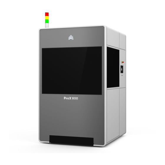
- Page 1 ProX™ 800 3D Production Printer User Guide Original Instructions Rev. E P/N 40-D044 3D Systems, Inc.
-
Page 2: Table Of Contents
ProX 800 Material Safety Data Sheets and Safety Data Sheets (MSDS/SDS)....... - Page 3 Replace the Tubing in the Peristaltic Pump ............. . .68 3D Systems, Inc.
- Page 4 GLOSSARY . . . . . . . . . . . . . . . . . . . . . . . . . . . . . . . . . . . . . . . . . . . . . . . . . . . . . . . . . . . . . . . . . . . . . . . . . . . . . . . . . . . . . . . . . . . 79 3D Systems, Inc.
-
Page 5: Introduction To The Prox™ 800 3D Printer
58, you will find a listing and descriptions of the documents related to In the section the ProX 800, including the ProX 800 Facility Guide, ProX 800 Material Guides, ProX 800 Material Safety Data Sheets and Safety Data Sheets (MSDS/SDS), and 3D Manage Software Documentation. -
Page 6: Additional Documentation
ProX 800 MATERIAL GUIDES The Material Guides detail the use of materials that have been certified for use with the ProX 800. Each material has its own Material Guide. Information specific to each material is included in the guides. -
Page 7: General Safety
Always follow the safety procedures. Do not, in any way, risk injury by working dangerously. Safety is a part of work, and not an obstacle to it. The ProX 800 was designed with safety in mind; however, improper use and malfunctions can cause injury. To prevent unsafe operation, the ProX 800 automatically shuts down immediately if it detects an unsafe condition. -
Page 8: Laser Safety
5 LASER SAFETY The ProX 800 uses a UV (ultraviolet) solid-state frequency tripled Nd:YVO4 laser which utilizes a 355 nm wavelength laser with a maximum power output of 3 watts (EN/IEC 60825-1:2007). The laser is located in the Printhead area of the ProX 800. For an overview of the printhead, refer to the section “Printhead Overview”... -
Page 9: Safety Labels And Interlocks
Laser safety labels are located at system entry locations which are indicated below. An interlock is located close to each label. LASER SAFETY WARNING LABELS Laser safety warning labels for the ProX 800 are located at system locations which are indicated above. SAFETY INTERLOCK SWITCHES Safety interlock switches protect the user from possible UV Laser radiation exposure when certain doors or panels are opened. - Page 10 DANGER Laser radiation WARNING when open. Laser ON Laser when lit. Class IV 355nm 1.5Watt 120 microJoule Maximum UV Laser. This device complies with 21 CFR chapter 1 subchapter J. Printhead 3D Systems, Inc.
-
Page 11: Voltage, Compliance, And Id Labels
VOLTAGE, COMPLIANCE, AND ID LABELS Laser Label, Maximum Wattage cTÜVus Label Rear of ProX 800 CE Mark Label Product ID Label, Voltage 3D Systems, Inc. - Page 12 MDM Product ID, Voltage Label Model: MDM ProX™ 800 Material Delivery Module for ProX™ 800 100-240VAC • 50-60Hz • 1PH • 6A 3D Systems Corporation 333 Three D Systems Circle, Rock Hill, SC 29730 USA 286510-00 3D Systems, Inc.
- Page 13 Chamber controller panel AC Electronics Panel Main Power Disconnect Switch 3D Systems, Inc.
-
Page 14: Chemical Safety
Protect print material from sunlight and ambient room light. Print material may be stored in material carts with the lid securely fastened. Material for the ProX 800 is composed of reactive monomers and oligomers. If improperly stored or handled, these compositions may undergo polymerization resulting in the emission of heat. -
Page 15: Shelf Life
In-Service Life In-service life of the print materials is defined as the useful life of the material after having been poured into the ProX 800 MDM. The in-service life of the ProX 800 material greatly varies depending on material type, usage and environmental conditions. -
Page 16: First Aid And Protective Equipment
1.4 kW. We recommend an HVAC system that changes the air two to five times per hour. To avoid adversely affecting part quality, do not expose the ProX 800 system to direct air flow from the air conditioning system. -
Page 17: Prox 800 System Components
Below is an overview of these components. ProX 800 PRODUCTION PRINTER This section will introduce you to the locations and component descriptions of the ProX 800 printer. There are two views: an outside view and an inside view. -
Page 18: Prox 800 Printer - Inside View
ProX 800 Printer - Inside View Two Chamber lights inside print chamber Both inner and outer electrical panels are removed E-Stop: The E-Stop immediately disables all motion controls and the laser, rendering them safe. After being pressed, it remains in the closed state until it is manually returned to the open state by pulling the red knob and turning it clockwise. - Page 19 The reset button resets the system’s controller. Inner Electrical Panel System Controller: A computer which controls the printer is located inside the electrical cabinet. The user does not have direct access to this device. The touchscreen user interface provides all user functionality. 3D Systems, Inc.
-
Page 20: Material Delivery Module (Mdm)
Stand-by Mode In this mode, the MDM is offline and operates independently from the ProX 800. When the MDM is plugged into a standard wall socket the module self-regulates the temperature keeping it stable and at operating temperature. The material can warm effectively in this mode, enabling the user to print a part while warming material for future use, allowing for no down time. - Page 21 MDM. This information prevents use of the wrong material, incorrect material use, or use of an empty or expired container, ensuring the material is safe to use. 3D Systems, Inc.
- Page 22 This reservoir is used to store material for transferring into or out of the print area to maintain the precise material height during printing. Applicator Rest: This rest area is used to stow the removable applicator when changing MDMs. 3D Systems, Inc.
-
Page 23: Printhead Overview
PRINTHEAD OVERVIEW The Printhead contains all components which power and control the laser and optics system of the printer. Only 3D Systems Certified Service Engineers are permitted to access the inside of the Printhead. IPM (Image Print Module): The IPM contains the laser, optics, and scanning/drawing system. -
Page 24: User Interface
. See the illustration below for the switch location . LED Indicators: The LED indicators indicate the readiness of the machine and its Lasers. ProX 800 User Interface • “Laser” Blue LED - ON, Solid » Printhead enabled » Printhead disabled or off. -
Page 25: Light Stack
MANUAL OFFLOAD CART The manual offload cart is an optional accessory for all ProX 800 models. The offload cart allows you to easily remove the print pad when it is loaded with a large or heavy part and transport it to the finishing area where supports are removed and the part is cleaned before it is cured. -
Page 26: Software Overview
. 42 . The touchscreen of the ProX 800 uses 3D Systems’ Print3D Pro™ printer controller software. The Print3D Pro runs on a Google™ Nexus 10™ tablet running the Android™ operating system which provides standard functionality for navigation, notifications, and application control. -
Page 27: Status Screen
Preset Views: The 3D model has 3 preset views. From manual for further information about these parameters. left to right, they are: front, isometric, and top. Current Layer: The end value of the layer currently being printed. 3D Systems, Inc. -
Page 28: Print Queue Screen
Alternatively, you can exit the queue and go back– it will automatically refresh the list. Unlock Door: Pressing this button will toggle the doors between Lock and Unlock positions. Queued Files: Number of files currently in the 3D Systems, Inc. -
Page 29: Print History Screen
PRINT HISTORY SCREEN The Print History screen gives the user access to information and functions related to previous print jobs. ProX 800 Folder (by month): The print history is sorted and grouped by month. Press anywhere on the black bar to see a list of the print jobs for that month. -
Page 30: Detail Pop-Up Screen
This screen provides additional actions that a user can perform on a file. It is displayed when the button is pressed on the Print Queue Screen. ProX 800 Filename: The print job on which to perform additional actions. Move to Top of Queue: Move the current job to the top of the print queue. -
Page 31: Material Status Screen
Displays the weight of the material in the leveling reservoir. Refill Bottle: Displays the weight of the material in the refill container. MDM Level: Indicates the amount of material in the MDM. The line indicates the nominal level of the material. 3D Systems, Inc. -
Page 32: Tools Menu Screen
“Print Applicator Screen” on page Printhead: “Printhead The Printhead Screen gives the user access to functionality of the Printhead. See the section Settings Screen” on page 35 for more information. Shutdown: This feature shuts down the printer. 3D Systems, Inc. -
Page 33: Elevator/Leveler Settings Screen
ELEVATOR/LEVELER SETTINGS SCREEN The Elevator/Leveler Settings Screen allows you to operate the elevator manually. ProX 800 Print Offload Manual Motions: as the position. The offload position comes pre-set in the software; however, some Move to Home: Move the elevator to its home adjustments may need to be made. -
Page 34: Print Applicator Screen
Back: Navigate back to the “Tools Menu Screen” on page Allow Motion / Motion Not Allowed: This message pops up when you open the screen. It indicates whether or not the system is in a 3D Systems, Inc. -
Page 35: Printhead Settings Screen
Navigate back to the “Tools Menu Screen” on Move to Rest: Move the IPM Beam to the stored page rest position. Check Laser: Checks the IPM power and returns a value based on the IPM power setting. 3D Systems, Inc. -
Page 36: Settings Screen
“Scale Factor Settings Screen” on page Build Settings: Navigate to the Build Settings screen. See the section “Build Settings Screen” on page Drawing Settings: Navigate to the Drawing Settings screen. See the section “Drawing Settings Screen” on page 3D Systems, Inc. -
Page 37: Manual Printer Connection Screen
Your printer should already be networked correctly, in which case you will not see this screen. If it becomes necessary to set the network connection up manually, the Settings tab will appear after you launch the Print3D Pro application. ProX 800 ProX 800... -
Page 38: Printer Information Settings Screen
PRINTER INFORMATION SETTINGS SCREEN Here you will find the printer name, printer serial number, 3D Systems SLA controller software build version and build date, and the Print3D Pro version installed on your printer. NETWORK SETTINGS SCREEN The Network Settings Screen allows the user to view the values related to the system network. -
Page 39: Heater Settings Screen
Edit the temperature for the MDM heater. For any field that you need to set, press the key to edit. Set Print Chamber Temperature: Saves the settings for the Print Chamber Temperature Set MDM Temperature: Saves the settings for the MDM Temperature. 3D Systems, Inc. -
Page 40: Scale Factor Settings Screen
Edit the current x-axis scale factor. Y Value: Edit the current y-axis scale factor. Z Value: Edit the current z-axis scale factor. Set Scale: Saves the Scale settings. For any field that is editable, press the key to edit. 3D Systems, Inc. -
Page 41: Build Settings Screen
MDM after the print is finished so that the excess material drains off of the part. Smart Sweep confines the sweeper motion to only the area of the parts being printed. This is the default mode. ProX 800 3D Systems, Inc. -
Page 42: Drawing Settings Screen
NEW FUNCTIONALITY FOR GUI V1 .1 .5443 RESTART BUILD WIZARD In GUI v1.1.5443, this feature provides the user more control over the process of restarting a build that has been interrupted. Select Restart Last Job from the status screen. 3D Systems, Inc. - Page 43 RECOAT PARAMETER MODIFICATIONS ON-THE-FLY WIZARD In GUI v1.1.5443, this feature assists with making mid-build recoat adjustments. To access this wizard while a build is in progress, tap the Recoat Style button. 3D Systems, Inc.
- Page 44 All modifications can be reverted by selecting Restore Ranges. When you tap the Edit button next to Support Recoat Style, you will see the dialog window at the right. NOTE: It is not recommended to add sweeps to this range . 3D Systems, Inc.
- Page 45 3D Manage. The user selects start and end Z ranges. 10. Ranges added between existing ranges will automatically create additional ranges to fill in the full Z range. Example: Add range 12mm- 20mm to a build with Z range of 0-21.2mm 3D Systems, Inc.
- Page 46 Once the Stir wizard is opened, the user is granted more control over how the machine Stirs the material. While the machine is stirring, the user will be shown a countdown to when the stir will end, seen at right. 3D Systems, Inc.
-
Page 47: 3Dsprint Software Overview
3D SPRINT is the 3D Systems’ software application used for preparing CAD models to be printed on an SLA printer. It is installed on a standalone computer which is provided by the customer. Double-click the 3D SPRINT icon on your computer/ laptop, or select it from your list of available programs loaded on your computer. -
Page 48: System Operations
The applicator, which contacts the material, can be removed from the ProX 800. The applicator should be kept with the MDM so that when the material is changed, the applicator remains with the material that it has been in contact with. -
Page 49: Print Applicator Cleaning
MDM . Any change in the printer’s inner frame placement will require recalibration by a trained service technician . 1. Open the front door of the ProX 800. Make sure that the connecting cables are out of the way before you attempt to place the MDM into the machine (1). - Page 50 Heater Settings Screen to verify that the temperature of the MDM is 28 °C (+/- 3 °C). Refer to the section, “Heater Settings Screen” on page 39 for details on the screen functionality. Power Connector Power Switch 3D Systems, Inc.
-
Page 51: Mdm Removal
MATERIAL DELIVERY MODULE TEMPERATURE CONTROL The ProX 800 offers offline and online heating. When the power cord from the machine is connected to the MDM, the system has online heating. When the power from a wall outlet is connected, the system has offline heating. The MDM can be heated either outside the system enclosure, via the stand-by mode, or inside the enclosure. -
Page 52: Installing Material Containers
. 8. Pull the release lever up to close the material bin, until it latches securely. 9. Close the print chamber door. Vent Release Lever Material Bin Release Button Material Container MDM showing material container location 3D Systems, Inc. -
Page 53: Material Container Removal
3. Push the container 4. Lift the material container out of the material bin. Dispose of the container according to local regulations. 5. Wipe any material spills from the bin, MDM, and floor with isopropyl alcohol and paper towels. 3D Systems, Inc. -
Page 54: Setting The Offload Position
Move Distance. ProX 800 1. The editing keypad pops up. Type in the amount to move (ex. “.5” will move print pad up ½”). This is a good place to start. 2. Press Set. 3. Repeat these steps until the print pad is far enough up to get the Manual Offload Cart under it without damaging the recoater or to reach the timing plate. - Page 55 . This moves the print pad down ½” . 5. Select Set Offload (1). NOTE: This position will now be saved and can be used from now on by selecting Move to Offload (2) . ProX 800 3D Systems, Inc.
-
Page 56: Printing A Part
If necessary, turn the machine on by ensuring that the printer is plugged in, then turning the power disconnect switch to the ON position. For the location of the switch, see the section “ProX 800 Printer - Inside View” on page Press the... -
Page 57: Setting The Start Position
The Omron Sensor does not read approximately 30.000 (+/- 0.001). Print Pad NOTE: See illustrations of the locations of these items in the section, “ProX 800 Printer - Inside View” on page Submerged If any one of these conditions exists, the Start Position must be set. -
Page 58: Removing Bubbles
Select the file you wish to print and press the button. The file selected should be loaded in the Print Queue. If the file is not in the top position, tap the file to highlight it, ProX 800 then tap the Jump to Top button to move the file to the top of the queue (3). -
Page 59: Drain The Build Platform
(Figure arm fits in build platform hole Figure 2 - Draining build platform in tilted position (pic- tured without build parts) 3D Systems, Inc. -
Page 60: Installation Of Print Platform Without Offload Cart
. Print Pad L-Shaped Guides Elevator Platform Print Pad inside Print Chamber (MDM not shown for clarity, but should be installed) Front print pad notched guides 3D Systems, Inc. -
Page 61: Installation Of Print Platform With Offload Cart
.” If so, press Print Applicator > Move to Home . 2. Lower the print platform onto the elevator forks by pulling lever on the offload cart down. 3. Perform steps 2-5 on the previous page. Pull adjustment lever down 3D Systems, Inc. -
Page 62: Remove Print Platform Without Offload Cart
Remove Print Platform Without Offload Cart ProX 800 1. Navigate to Tools > Elevator/Leveler Settings and press Move to Offload. This will move the recoater down 2” and the print pad up. If you have a material offload cart, skip to “Remove Build Platform With Offload Cart”... -
Page 63: Remove Print Platform With Offload Cart
4. Push the adjustment lever on the cart to the down position to lift the print pad off of the elevator 5. Using the handles on the cart, carefully pull the print pad out of the machine. To remove build parts from the platform, follow the steps outlined in the section Post Processing of Build Parts. 3D Systems, Inc. -
Page 64: Post-Processing Build Parts
13 Due to the large size of the ProX 800 build platform and the potentially large size of printed parts, it is highly recommended to post-process parts with a two-RAMCO system, one filled with TPM (Tripropylene Glycol Methyl Ether) and the other with IPA (Isopropyl Alcohol). - Page 65 Set build platform on offload cart or other large, sturdy cart to prepare for part removal. With nitrile gloves on, use a putty knife or other viable tool to scrape the build’s supports off the build platform. Carefully remove other support structures by hand. 3D Systems, Inc.
- Page 66 . For either solvent, closely monitor how well it is stripping your build of uncured material . If it is no longer cleaning build parts and/or cleaning takes excessive effort, it is time to switch out solvents for fresh batches . 3D Systems, Inc.
-
Page 67: Maintenance
. DUST REMOVAL Remove dust from the outer surfaces of the ProX 800 by wiping with a clean, dry, lint-free cloth. CAUTION! Do not remove any outer panels when cleaning the system . Panels must be removed only by a qualified 3D Systems Customer Support Representative. -
Page 68: Replace The Tubing In The Peristaltic Pump
2. Tighten the reservoir connection valve (1) by turning it clockwise to stop the flow of print material. 3. Loosen the two hose clamps from the valves using a flathead screwdriver. (2) MDM Pump Connection Peristaltic Pump Leveling Reservoir Hose clamp Pump Tubing Pump Connection MDM Showing Pump Tubing 3D Systems, Inc. - Page 69 7. While squeezing the two tabs together on the pump mechanism (7), use the latch to rotate the mechanism until the hose is freed (8). Tabs Turn mechanism to remove hose Latch Squeeze two tabs together to release hose. Use latch to turn mechanism. 3D Systems, Inc.
-
Page 70: Reboot The Computer
Open valve on the lower hose connection by turning counterclockwise. Reboot the Computer PC Reset “ProX 800 If it becomes necessary to reboot the computer, press the button on the electrical panel. See the section Printer - Inside View” on page 18 for an illustration. -
Page 71: Troubleshooting
15 TROUBLESHOOTING Below is a brief outline of some simple troubleshooting procedures for the ProX 800. For electrical diagrams, see the following placard illustrations which are also physically located on the machine: “Power Panel Connections Placard” on page 63 •... -
Page 72: Power Panel Connections Placard
POWER PANEL CONNECTIONS PLACARD AIR HEATER LASER LSR INTLK ELEVATOR USER INTFC DOOR SW 3D Systems, Inc. -
Page 73: Power Panel Layout Placard
TERMINAL BLOCK ST2.5 TB2-C TERMINAL BLOCK ST2.5 START LT TB2-D TERMINAL BLOCK ST2.5 TB2-E TERMINAL BLOCK ST2.5 ENA STAT ESTOP MONITOR ESTOP SWITCHES DOOR SWITCH MONITOR DOOR & WINDOW SWITCHES 287372-00 DOOR SWITCH MONITOR IPM DOOR SWITCHES 3D Systems, Inc. -
Page 74: Electrical Block Diagram Placard
ELECTRICAL BLOCK DIAGRAM PLACARD 3D Systems, Inc. -
Page 75: Chamber Controller Placard
DIGITAL SENSORS LIMS, REC BAR VACUUM SENSOR 4PR SHLD RESIN HT, VAC PROX SENSOR RECOAT PCB FAN POWER (24V) THERMISTOR CB21 DUAL +24V HEATER ELEMENT -12V ENCLOSURE FANS LINE INPUT (FROM ESTOP CONTACTORS) LV PS LINE INPUT 3D Systems, Inc. -
Page 76: Customer Support
“Laser Safety” on page The ProX 800 conforms to applicable requirements of 21 CFR Subchapter J at the date of manufacture. It is designated a Class I Laser Device by the Center for Devices and Radiological Health (CDRH). In normal operation, the Laser beams are completely confined and the viewing windows in the Process Module block the UV Laser radiation. -
Page 77: Legal Notices
(the “Licensed User”) does not have the right to copy, reproduce, or translate this document in any way or to any media without the prior written consent of 3D Systems, Inc. No copies of the document may be sold or given to any person or other entity. -
Page 78: Ec Declaration Of Conformity
3D Systems, Inc. -
Page 79: Glossary
The total light energy absorbed by a point on the material surface. Exposure increases with higher Laser power and decreases with higher drawing speed. Fill vectors (skin fill) Overlapping parallel vectors that comprise the horizontal surfaces (skins) of stereolithographic parts. 3D Systems, Inc. - Page 80 The process of linking small molecules (monomers) into larger molecules (polymers) comprised of many monomer units. Post-Curing Apparatus (PCA) and ProCure equipment A device which generates ultraviolet energy used to cure green stereolithographic parts. Post-process The process of cleaning, curing, and finishing stereolithographic parts. Print3D Pro 3D Systems, Inc.
- Page 81 L-shaped brackets that support the print pad and attach it to the elevator. Material Delivery Module (MDM) The metal container inside the process chamber in the ProX 800 that holds the material from which the part is formed. On older SLA Centers, the MDM is referred to as the vat.
- Page 82 Electromagnetic radiation having a wavelength shorter than visible light, (i.e., below 390 nanometers). On older SLA Centers, the metal container inside the process chamber that holds the material from which the object is formed. On the ProX 800, this container is called the MDM. Vector A directed line segment represented by starting and ending coordinates as defined in a stereolithography slice or print file.
- Page 83 3D Systems, Inc. 333 Three D Systems Circle | Rock Hill, SC | 29730 www.3dsystems.com ©2017 3D Systems, Inc. All rights reserved. p/n 40-D044, Rev. E 3D Systems, Inc.
Need help?
Do you have a question about the ProX 800 and is the answer not in the manual?
Questions and answers