Table of Contents
Advertisement
Advertisement
Table of Contents

Related Manuals for 3D Systems DMP Flex 350


Summary of Contents for 3D Systems DMP Flex 350
- Page 1 DMP Flex 350 Production printer User guide Original instructions...
-
Page 2: Table Of Contents
2.3.9 Sharp Edges on the Printed Part 2.3.10 Weak Mechanical Integrity on the Printed Parts 2.4 Special Considerations - Reactive Metals 2.4.1 Electrical Equipment 2.4.2 Fire Suppression 2.4.3 Good Housekeeping 2.5 Lock-out/Tag-out 2.5.1 Policy 2.5.2 Principles, Beliefs and Philosophy 2.5.3 Rules 2.5.4 Electrical Lockout-tagout Procedure 2.5.5 Remove Energy Stored in Argon and Compressed Air Lines 2.5.6 Restore Equipment to Service 2.5.7 Procedure Involving More than One Person 2.6 Safety Interlocks 2.6.1 Stack Light 2.6.2 Shut-off Matrix 3D Systems, Inc. p/n 15-D100, rev D... - Page 3 4.5.3 Menu Bar 4.5.4 Tabs 4.6 DMP Monitoring (optional) 4.7 DMP Server 4.8 Backup DMP Server 4.9 Bringing DMP Server to a Domain SYSTEM USE 5.1 Start up DMP Flex 350 5.2 Prepare System 5.2.1 Add Powder 5.2.2 Install Build Plate 5.2.3 Install New Coater Strip 5.2.4 Prepare Build Plate 5.2.5 Clean Laser Window 5.3 Inert System 5.3.1 Close Printer Door 5.3.2 Run Inertion Cycle 3D Systems, Inc. p/n 15-D100, rev D...
- Page 4 6.3 Monthly 6.3.1 Check Pressure Levels 6.3.2 Check Emergency Off Buttons 6.3.3 Check Chiller Temperature and Water Level 6.3.4 Clean Vent Opening 6.3.5 Check Printer Gloves 6.3.6 Automatic Laser Power Calibration 6.4 Every 3 Months 6.4.1 Replace Chiller Fluid 6.4.2 Clean Machine Exterior 6.4.3 Check Oil Level Blower 6.4.4 Check Oil Level Vacuum Pump 6.5 After 1600 Job Hours 6.5.1 Replace Process Filter 6.6 Every 6 Months / 2000 Hours 6.6.1 Clean Overpressure Valve 6.6.2 Clean Vacuum Pump Ventilator 3D Systems, Inc. p/n 15-D100, rev D...
- Page 5 7.3 Re-install Scanner Driver Files 7.3.1 Symptoms 7.3.2 Prerequisites 7.3.3 Solution 7.4 Reinstall or Restore a Broken DMP Server Computer 7.5 DMP Explorer 7.5.1 Solid Supports are Failing to Process 7.5.2 Processing Fails with “Errors during hatching” 7.5.3 Slicing and hatching a large, complex part takes longer than 2 days and crashes 7.5.4 Processing of block supports fails 7.5.5 Speed up the slicing, hatching and processing of multiple parts 7.5.6 My Computer is slow when DMP Worker is enabled 7.6 DMP DEPOSITION 7.6.1 Fix ‘Unsafe filter pressure’ message 7.6.2 Detecting of job processing capability failed after restarting DMP Deposition BASIC REGULATIONS 8.1 EC Declaration of Conformity (DoC) 3D Systems, Inc. p/n 15-D100, rev D...
-
Page 6: Introduction
INTRODUCTION The DMP Flex 350 production printer is a high quality direct metal printing (DMP) machine. It brings reliability and repeatability to production-level direct metal printing. The DMP Flex 350 is designed to meet industrial market demands of reliable and low maintenance 3D printing machines. With direct metal printing, parts are built up layer by layer. Using this technique, complex parts can be made. Loose metal powder particles are melted together by a high-precision laser. The laser is focused on the powder particles in order to selectively build up thin subsequent horizontal layers. By connecting each new layer to the previous one, it brings a high quality alternative to the traditional manufacturing processes. Since no tools are used and no material is removed, waste is reduced significantly. Parts are not built by removing material in subsequent steps, but by adding material. Other advantages are the quick set-up times and the ability to produce very complex assemblies as a single part. The DMP Flex 350 production printer has a build platform of 275 x 275 x 420mm (including build plate) which can produce large size and high quality parts in a variety of metals. The machine features easy cleaning and rapid material switching. DMP Factory 350 The system is upgradeable to the DMP Factory 350 solution, where an additional module, i.e. the Powder Management Module (PMU) provides the customer with increased powder management and a closed powder handling system. Use the instructions and information in this guide to operate the DMP Flex 350 production printer. Before operating this equipment, please read this guide carefully to ensure safety. 1.1 Limitations of Warranty and Liability This information is provided by 3D Systems for the convenience of its customers. It is believed to be reliable, but no representations, guarantees or warranties of any kind are made as to its accuracy, fi tness for a particular use, or the results to be obtained therefrom. The information is based in whole or in large part on laboratory work and does not necessarily indicate performance in all conditions. Not withstanding any information provided by 3D Systems or its affi liates, the customer remains fully responsible for determining which federal, state, or local laws or regulations, or industry practices are relevant to activities in which it engages, as well as assuring that those laws, regulations, or standards are complied with under actual operating conditions, and 3D Systems undertakes no responsibility in these areas. In no event is 3D Systems responsible for damages... -
Page 7: Oxygen Limits
Caution: Once the DMP Factory 500 Printer Module is installed, it should not be moved without the aid of a qualified, 3D Systems CSE. 3D Systems accepts no responsibility for damage to the modules by anyone other than 3D Systems CSE. -
Page 8: Definitions And Names
1.6 Definitions and Names In this guide and in the software the following roles are defined: • Operator. An operator performs standard task on the PTM: daily operations and preventive maintenance. • Engineer. An engineer has knowledge of the system and performs basic troubleshooting. • Certified Service Engineer (CSE). Is certified by 3D Systems to perform all maintenance and troubleshooting. 3D Systems, Inc. p/n: 15-D100, rev. D... -
Page 9: Safety Guidelines
SAFETY GUIDELINES 2.1 Safety Labels 2.1.1 ID Labels 1 x at the rear of the printer process chamber 1 x at the front of the printer module 1 x at the front of the printer module cart 3D Systems, Inc. p/n: 15-D100, rev. D... - Page 10 2.1.2 Laser Certification / Identification 1 x at the rear of the electrical cabinet in the top left corner 2.1.3 Laser Fiber Label 2 x at the rear of the printer, next to the collimator. 3D Systems, Inc. p/n: 15-D100, rev. D...
- Page 11 2.1.4 Laser Safety Label 1 x on the scanner 1 x on the printer door 3D Systems, Inc. p/n: 15-D100, rev. D...
- Page 12 2.1.5 Pinch Point Warning 3 x on the printer module 4 x on the printer door 1 x pneumatics cabinet printer 3D Systems, Inc. p/n: 15-D100, rev. D...
- Page 13 2.1.6 Tip Over Warning Label 1 x on the printer door 1 x on the counterweight 2 x on either side of the counterweight 3D Systems, Inc. p/n: 15-D100, rev. D...
- Page 14 2.1.7 Burn Hazard Warning Label 3 x at the rear of the process chamber, adjacent to the oxygen sensors 2.1.8 Electrocution Warning Label 1 x on the electrical cabinet 3D Systems, Inc. p/n: 15-D100, rev. D...
- Page 15 2.1.9 Dust Inhalation Label 1 x in the top right corner of the printer door 3D Systems, Inc. p/n: 15-D100, rev. D...
- Page 16 2.1.10 Restricted Access Label 8 x total: • 1 x electrical cabinet • 1 x laser compartiment • 1 x each pneumatics cabinet • 1 x blower tower 3D Systems, Inc. p/n: 15-D100, rev. D...
-
Page 17: Foreseeable Misuse
Use the System in an industrial setting only. Use of the System in a non-industrial settings might lead to: accumulation of metal powder, improper housekeeping, insufficient illumination, unauthorized and untrained persons access to the equipment, improper ventilation and other hazardous situations. All of these situations may lead to serious injury or damage to the equipment. • Do not operate the System without skinning. This may lead to pinch, crush and clamp of fingers, limbs or even body and to serious injury and possible damage to the machine. • Do not move the RPM from or to the system by any other means than the RPM cart. If the RPM is moved with something other than the RPM cart, the RPM might fall and lead to injury or damage to the equipment. If the RPM is moved with something other than the RPM cart, the RPM may fall and spill metal powder. A dust cloud of other metal powder might lead to health risks and / or serious injury. • Do not remove excessive metal powder from the RPM and the printed part after a print task, when the RPM is still in the system. • Do not move the coater by hand, use the software and the hold-to-run button on the system. Do not bring a limb inside the system to force the coater to move. This may lead to pinch, crush and clamp of fingers or limbs, serious injury or damage to the equipment. • Do not try to open the process filter. This may lead to an invasion of air in the process filter, and as a reactive metal powder is in use: potential fire or explosion. This may lead to serious injury or damage to the equipment and as a non- reactive metal powder is used: potential fire. This might lead to serious injury or damage to the equipment. • Do not over-extend the lifetime of the process filter. Replace the process filter when the differential pressure sensor indicates to do so in the machine software. • If the process filter is not replaced in time, this may lead to accumulation of metal powder and other flammable material in the process filter, which may lead to a potential fire or explosion, serious injury or damage to the equipment. • Do not open the top lid when working with the vacuum blower cart, the blower is still within the machine structure. Pull out the blower before opening the lid. Make sure all pipes are disconnected. 3D Systems, Inc. p/n: 15-D100, rev. D... -
Page 18: Residual Risks
The movement Crush or cut of a the edges of the process button to move the coater at low speed at a of the coater in finger or limb chamber. safe distance of the limbs. operator mode • between the coater and the Do not move the coater manually. edges of the RPM. A person slips on loose powder Good housekeeping prevents slips, trips Slippery soil Slip, trip or fall on the floor. and falls. In case of argon leaks, stop the machine, close the main supply valve, as needed Inhalation of large quantities of evacuate the area and contact the CSE. Argon Suffocation argon gas can lead to suffocation Regularly inspect the oxygen monitor in the facility as required by local regulations. 2.3.5 Contact Hazards The use of certain metal powders can lead to irritation or allergic reactions on the skin, use the PPE as indicated in this user guide, the Safety Guide and the Facility Guide. 3D Systems, Inc. p/n: 15-D100, rev. D... -
Page 19: Radiation Hazards
2.3.10 Weak Mechanical Integrity on the Printed Parts 3D Systems considers the design of the printed part the customers responsibility. When the operator removes the printed part from the system, these movements might cause the part to break or pieces to fall. This may harm the operator, damage the RPM or damage the printed part. It is recommended to move the printed part carefully. Note: 3D Systems cannot be held responsible for harm to an operator, damage to the RPM or printer, or damage to a printed part due to improper design. 3D Systems, Inc. p/n: 15-D100, rev. D... -
Page 20: Special Considerations - Reactive Metals
D is not effective against. Caution: Personnel must be trained on fire prevention and suppression. 2.4.3 Good Housekeeping Make sure that dust layers, clouds or dangerous concentrations of dust are avoided by good housekeeping. Examples of good housekeeping include, but are not limited to: • Using a wet separator, explosion-proof vacuum cleaner after each use. The RPM must be throughly cleaned before moving to the next module, to avoid potential dust clouds. • Using a floor cleaning machine at the end of each shift, to avoid dust layers around the modules and on the production floor. • Using a dust extraction system to remove airborne dust out of the air any time metal powder is handled. • Using pure ethanol to wipe down the modules after each use and before transporting the RPM. 3D Systems, Inc. p/n: 15-D100, rev. D... -
Page 21: Lock-Out/Tag-Out
In the operation and maintenance of the DMP system, it is necessary to inspect, repair, clean, adjust or work on equipment, facilities, and instruments of all types. 3D Systems’ policy is that this work will be done with maximum safety to all personnel and equipment involved. Individuals must assume responsibility for their own safety as well as that of fellow employees. This Lockout and Tag Procedure is essential to fulfill that responsibility and must be followed in all areas. 2.5.2 Principles, Beliefs and Philosophy Principles: The following principles provide the basis for lockout and tag: • Lockout is defined as the determination by area management, operating personnel, or service personnel that the equipment or process needs to be isolated for repair, adjustment, or replacement so that inadvertent operation of the equipment or process does not cause injury. • Servicing equipment in a powered-on condition presents unique hazards and must be performed only by personnel trained to perform the needed functions. When dealing with potentially hazardous situations, approved area procedures must define how to troubleshoot or operate equipment or processes in a safe manner. If there are no area-approved troubleshooting or operating procedures, then the equipment or process must be locked out. Beliefs: 3D Systems believes the following: • All equipment and processes can be worked on safely by eliminating the hazards or by taking precautions to protect people. Philosophy: Our philosophy is to secure energized or power-driven equipment prior to adjusting, repairing, or replacing in a way that protects employees and customers from injury and equipment from damage. 2.5.3 Rules • All equipment shall be locked out to protect against accidental or inadvertent operation when such operation could cause injury to personnel. Do not attempt to operate any switch, valve, or other energy isolating device bearing a lock. • The electrical disconnect panels of all equipment bays not in use must be locked out/tagged out by the area manager. 2.5.4 Electrical Lockout-tagout Procedure 1. Switch off the machine following the regular shutdown procedure. 3D Systems, Inc. p/n: 15-D100, rev. D... -
Page 22: Remove Energy Stored In Argon And Compressed Air Lines
4. Verify zero energy status by using the operating controls (buttons on the control panel). 5. Open the electrical cabinet and measure if any electrical energy is present on the secondary side of the main power switch. 2.5.5 Remove Energy Stored in Argon and Compressed Air Lines The main argon valve and main compressed air valve are located at the rear of the printer. 1. Turn these valves counterclockwise to cut off the main argon and compressed air supply. This will also remove any stored pressure in the system. 2. Install a lock on both control knobs to make certain the compressed air and argon gas supplies cannot be turned on accidentally while the system is being serviced. 2.5.6 Restore Equipment to Service When the job is complete and equipment is ready for testing or normal service, check the equipment area to see that no one is exposed. When equipment is all clear, remove all locks. The energy isolating devices may be operated to restore energy to equipment. 2.5.7 Procedure Involving More than One Person • In the preceding steps, if more than one individual is required to lock out equipment, each shall place his own personal lock on the energy isolating device(s). One designated individual of the work crew or a supervisor, with the knowledge of the crew, may lock out equipment for the whole crew. In such cases, it shall be the responsibility of the individual to carry out all steps of the lockout procedure and inform the crew when it is safe to work on the equipment. Additionally, the designated individual shall not remove a crew lock until it has been verified that all individuals are clear.. 3D Systems, Inc. p/n: 15-D100, rev. D... -
Page 23: Safety Interlocks
• A. White The white light indicates that the laser is active. • The white light stays on as long as the laser is activated. B. Green The green light indicates that the PTM is in operation. • In preparation for a print task or that a print task has ended • Is in safe mode. C. Orange The orange light indicates that the PTM is in operation, but a warning is generated. The orange stack light indicates a warning, perform the following: • Check the warning and follow standard procedures. • When a correction is not possible, request assistance from the engineer. When the situation is corrected, continue the operation of the PTM. If the situation cannot be corrected, request assistance from an Engineer. D. Red The red light indicates that the PTM is in operation and an alarm was activated by the software of the PTM or the safety PLC. The red stack light indicates an alarm, perform the following: • If the emergency off push button was not activated, follow standard procedures. • If the emergency off push button was activated, request assistance from an Engineer. When the situation is corrected, continue the operation of the PTM. If the situation cannot be corrected, request assistance from 3D Systems 3D Systems, Inc. p/n: 15-D100, rev. D... - Page 24 OPERATING EQUIPMENT WITH INTERLOCKS DEFEATED CAN CAUSE EQUIPMENT DAMAGE, INJURY, OR DEATH. IF YOU SUSPECT A SAFETY INTERLOCK DEVICE IS NOT WORKING PROPERLY, DO NOT OPERATE YOUR DMP EQUIPMENT. DISCONNECT POWER FROM THE EQUIPMENT AND CONTACT 3D SYSTEMS CUSTOMER SUPPORT FOR ASSISTANCE.
-
Page 25: Shut-Off Matrix
A. Emergency Off Emergency off, all safety groups stop or do not start. These do not stop: the safety PLC, the 24 V DC electrical power features and the built-in computer. B. Door of the Process Chamber Process chamber door is open: • The safety motor group stops or does not start. • Laser stops or do not start. • The coater and the steering of the build plate within the RPM stop or does not start • The coater can be moved with the correct software activation and the ‘hold-to-run’ button C. Pressure in the Process Chamber Pressure in the process chamber is under 150 mbar, the laser stops or does not start. D. Oxygen in the process chamber Oxygen level in the process chamber is over 2% or 230 ppm, the laser stops or does not start. 3D Systems, Inc. p/n: 15-D100, rev. D... -
Page 26: Dmp Flex 350 At A Glance
Argon • Maraging Steel Steel, Inconel, CoCr • Ni625 Sieving station (optional) Sieving mesh 60 µm Argon • Ni718 • CoCr F75 DMP Flex 350 printer Argon DMP Flex 350 printer type B DMP Flex 350 • AlSi7Mg0.6 DMP Flex 350 configuration B Argon • AlSi10Mg Aluminum Sieving station (optional) Sieving mesh 80 µm Argon For a more detailed overview of the specific hardware configurations and gas type combinations, please refer to the DMP Safety Guide (p/n: 80-D0712). 3D Systems, Inc. p/n: 15-D100, rev. D... -
Page 27: Dmp Flex 350 Start-Up Set
Allen keys, set 1,5 - 10 151436 Dust masks ( 5 pc box), 8835 ML 151437 Gloves, M - powder free, nitrile (box) 151438 Gloves, L- powder free, nitrile (box) 151439 Manual sieve, 63um (diam 305, 40mm) 151440 Collecting pan, SST, 305mm, Height 40mm 151444 Thermometer, Digital ThermoTester 151799 Coater cutting tool 151133 12654614 Strip RX SILIC 320x10x1,5 (1 pack of 200 pieces) 151712 Printing Plate, Titanium, 199 X 150 X 10mm 15-3534 Calibration plate, 274x274x6mm 151501 Highload Anchor, 24/50, M16 15-0162 Offset screwdriver, 9-40, Painted 15-4199 LED Flashlight, 1000lm, Rechargeable 15-4200 Lens filter set, Flashlight, Red-Green-Blue-Yellow 15-2414 Vision perspective calibration plate 320 -1-1-10800 15-4264 Tool, Door bolts 3D Systems, Inc. p/n: 15-D100, rev. D... -
Page 28: Dmp Flex
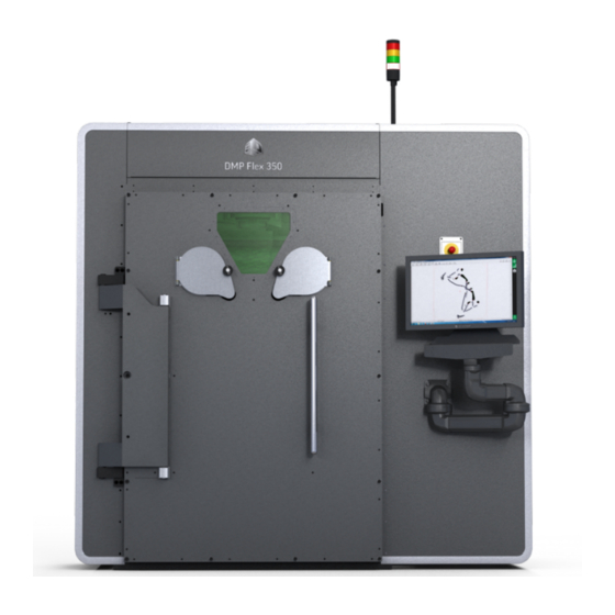
Process chamber window: allows the operator to look inside the process chamber but remain protected from laser radiation. Stack light: the stack light consists of four lights that indicate the state of the machine. • Red - Vital machine error • Orange - Error but machine is still operational • Green - Machine is fully operational • White - Laser is ready Control panel: the control panel holds all buttons used to start up the machine. • Emergency off: puts the machine in a safe state, activating the safety circuit • Key switch: switches between operator and service mode. • On: starts up the machine after turning on the main power switch and 24 V DC. • Hold to run: button that needs to be held in order to activate certain components. • USB 1 & 2: USB connections for external devices. Main power switch: The main power switch is used to switch the main 400V power supply to the printer on and off. Operator PC: the DMP Flex 350 printer module is controlled by this computer. 3D Systems, Inc. p/n: 15-D100, rev. D... - Page 29 Enable switch: this switch is reserved for Certified Service Engineers only and allows them to perform specific maintenance operations. WARNING: THE ENABLE SWITCH MUST REMAIN CONNECTED AT ALL TIMES. IF NOT, THE MACHINE WILL GO INTO EMERGENCY OFF STATE. Main argon valve - Main compressed air valve: these knobs will open/close the argon and compressed air supply to the DMP Flex 350 system. In case of a Lock Out-Tag Out (LOTO) procedure, close these knobs to shut off the main argon/compressed air supply. Closing these valves will also release any residual pressure in the tubing of the DMP Flex 350 system. 3D Systems, Inc. p/n: 15-D100, rev. D...
- Page 30 Collimator: Connection point of the laser optical fibre to the collimator in the DMP Flex 350 system. Vacuum pump: before starting a print job, the atmosphere inside the chamber needs to be oxygen free. The vacuum pump removes all air from the process chamber creating a vacuum in the process chamber. This allows the process chamber to be filled with argon gas to create inert atmosphere with oxygen levels lower than 100 parts per million (ppm). Blower: the blower continuously circulates the argon through the process chamber to extract all fumes and carry them to the process filter. Process filter: all fumes and debris extracted from the process chamber are filtered out by the filter before the argon atmosphere is reintroduced into the process chamber. 3D Systems, Inc. p/n: 15-D100, rev. D...
- Page 31 Caution: As a general rule, but especially in the case of a free-standing configuration, avoid installing the system in a location with a lot of facility traffic. This is to reduce the risk of hitting the system with a forklight and tipping over the system. 3D Systems, Inc. p/n: 15-D100, rev. D...
- Page 32 Laser window: the laser is focused onto the build platform through the laser window. Control box: allows user to operate the system while reaching inside the process chamber through the glove ports. • Emergency off button (a) • Mode Select button (b) • Hold-to-run button (c) • Action lever (d) RPM (Removable Printer Module): the RPM contains the metal powder and the build platform. It can be pulled outwards to have better access to the build platform for a powder switch, cleaning or maintenance. It can be removed and replaced by another RPM that contains a different metal powder. For more detailed information on the RPM, see next page. Locking pins: the locking pins lock the build module into place and maintain it in the correct position. These must be unlocked to pull the module in its outward position or to remove it. 3D Systems, Inc. p/n: 15-D100, rev. D...
- Page 33 Coater: is a deposition system that moves the powder from the feeds onto the build platform. Build chute (with build platform): the parts are printed on a build plate which is bolted to the build platform. During the print process, the build platform indexes down to allow subsequent layers of the part to be printed. Feed chute (with feed platform) (one on each side of the build platform): the feed chute (with feed platform) contains the metal powder supply. The platform lifts the powder to the correct height to supply the coater with the right amount of metal powder to deposit a new layer on the build platform. RPM blower: a fan that controls the gas flow over the powder bed on the build plate to remove the fumes created during the printing proces. Overflow chute (one on each side of the printer module): powder deposited in here is pushed to the overflow container. Overflow tank: holds the excess powder until it can be extracted and sieved for re-use. Electrical connectors: these carry all power and signal connections from the process chamber to the build module. Removable overflow container: allows the end user to empty the overflow tank. 3D Systems, Inc. p/n: 15-D100, rev. D...
- Page 34 Flex 350 RPM (removable printer module) out of the printer or store a DMP Flex 350 print module, in case of multiple print modules. This module cannot be used to transport any other types of loads. Chiller: the chiller is connected to the DMP Flex 350 system with flexible hoses and circulates and cools cooling liquid used to keep the laser components at a set temperature. It requires a mixture of tap water and a cooling fluid additive. The tap water must comply with the water quality standard mentioned in the table in §3.7 Chiller of the DMP Flex 350 Facility Guide (p/n: 15-D99). Cooling fluid additives recommended by SMC are: Hexid A4, Controlxid1642, CCl105, Cool flow IGE, Dowcal 100 and optishield +. The correct mixture of tap water and cooling fluid additives must be according to SMC guidelines. Caution: These cooling fluid additives need to be supplied by the customer. 3D Systems, Inc. p/n: 15-D100, rev. D...
-
Page 35: Software Overview
Background program DMP Remoting server Background program DMP Monitoring (optional) Process monitoring File preparation is typically performed in the following sequence. PRINTER • Create part file • Check job file • Print job files • Create job file • Compose job files • Machine controls • Assign process parameters • Set machine parameters • Change job parameters • Process monitoring File preparation is typically performed from a user PC although the DMP server can also be used to do file preparation if needed. 4.1 3DXpert™ 3DXpert is the all-in-one software solution for metal additive manufacturing. It contains all the necessary tools to assist the user in preparing a part for printing and sending it to the DMP Factory 350 printer. For more information on 3DXpert™ and creating a part for 3D printing, please refer to the relevant 3DXpert documentation available here. 3D Systems, Inc. p/n: 15-D100, rev. D... -
Page 36: Dmp Main Toolbar
4.2 DMP Main Toolbar To facilitate using all the different apps in the DMP software suite on the DMP printer, there is a new, central user interface. After installation, you will find an icon on your desktop with the serial number of your machine: All other DMP shortcuts and icons should be removed from the machine desktop and other start locations. The DMP tool bar is automatically started when you log in to Windows. Individual DMP apps can be started using a specialized task bar at the right of the screen. The task bar also gives a visual overview of the state of the components: • Black background: not started • Green background with blinking icon: starting • Green background: running • Yellow background with blinking icon: component lost connection to the machine server, but is still running • Red background with blinking icon: component is still running, but an error occurred during startup. An error message is displayed in a tool tip (move the mouse pointer over the icon) • Red background: Same as the previous, but the component is shut down Optional components (like DMP Monitoring) are only displayed when they are configured. 3D Systems, Inc. p/n: 15-D100, rev. D... -
Page 37: How To Begin
4.3 How to Begin To use the DMP software, you need to select a user and user level first. The user level determines the menus and options that are available in the components. You can switch user levels by clicking the tile on the bottom right corner of the screen: A red tile means no user/role is selected. On a green button the current user is displayed. When clicking the tile, a pop-up menu will appear which allows the user to select a user level. A red warning button will appear whenever the connection to DMP Machine Server is lost. 3D Systems, Inc. p/n: 15-D100, rev. D... -
Page 38: Dmp Control - Operator
Deposition. While it needs to be running on the machine PC to control the laser and scanner during printing, it can be run separately from a user PC to prepare the print job remotely and send it to a printer. The program is build up out of the following components: 4.4.1 Menu Bar • Add group: add a group of parts • Add parts: add one part at a time • Optional: ProductionWise module allows user to: • Start your serial manufacturing job in < 1 minute. • If set up properly, includes automatic individual ID tagging and serial number generation. • Centrally manage your serial manufacturing jobs. • All with traceability and version control • Save Job: saves the job as a .lmj file • Close Job: closes the job • Baseplate: lets the user change the build plate size 3D Systems, Inc. p/n: 15-D100, rev. D... -
Page 39: Preview Screen
• Parameters: manually allocate job and part parameters • Time: estimate job time • Job Analyzer: • Analyzes the job file for potential mistakes • Over 25 potential issues are checked • Includes (automatic) fixing for some issues • 3 different levels • Error (red): must be fixed otherwise job can’t be started • Warning (yellow): carefully read and see if it aligns with your intentions or not • Information (white): informative message • Process job: will open the Run job pop-up window. 4.4.2 Preview Screen • Shows a preview of the current selected layer for each part Calibrated scan area Selected layer of part to be printed Build plate Build platform 3D Systems, Inc. p/n: 15-D100, rev. D... -
Page 40: Positioning & Tools Panel
• Group list (B): this window shows a list of all groups that are part of the job file. Right-clicking a group brings up a number of options: • Rename group: allows the user to change the group name. • Delete group: this will delete the selected group. • Set scan to False for selected group: selecting this option will stop this group from being scanned during the remainder of the build. • Save group to file...: save a single group to a new job file • Convert clone group into mother group: converts a clone to a new mother file so its settings can be adjusted. • Select all copies of this group: this will select all clones of the selected mother group. • Group count: this number is the sum of the mother group plus all of its clones. 4.4.4 Layers Slider Bar Let’s you scroll through the layers in the preview window. By clicking in the bottom right corner you can specify which layer to show. The layers can also be scrolled trough by using the up / down arrow keys. 3D Systems, Inc. p/n: 15-D100, rev. D... -
Page 41: Properties
4.4.5 Properties By clicking the left bar of the Positioning & tools panel the window will switch to the Properties window. This window will display different parameters for the job, the group and the part (see image to the right). 3D Systems, Inc. p/n: 15-D100, rev. D... -
Page 42: Update Scanner Calibration File
2. Navigate to the Calibrations folder and to your machine serial number. 3. Download the latest version of the calibration file, e.g. D2_1224_LM45_v04.ct5 4. Copy this file to your machine and copy it into the folder C:\3D Systems\Config\Machines\LM45\Unit x. Caution: Make sure you place the file in the correct machine folder (LMxx, where xx is your machine serial number) but also in the correct optical unit folder. If your machine is equipped with only 1 laser/optical unit, place the file in the subfolder Unit 1. -
Page 43: Checking Slicing/Hatching Parameters
4.4.7 Checking Slicing/Hatching Parameters Once you have a job file, you can always trace back what hatching parameters were used. To find this information: 1. Open the job in DMP Control. 2. Click on the far left bar to switch to the Properties window. In the Group parameters subsection and the Part parameters subsection the Slicesettings can be checked. Here the slice settings will be displayed that are used to generate this part. 3D Systems, Inc. p/n: 15-D100, rev. D... -
Page 44: Building Close To The Platform Borders
Caution: Do not scan on the build module. The scanner zero point is not always in the center of the build platform. To verify that your part is not outside of the platform, you can ‘test’ the location by manually pointing the scanner to the test location. 1. Switch on the red laser diode/pointer to see the location of the spot. 2. Select Machine > Laser > check ‘Show laser diode’ 3. From DMP Control, select Machine > Scanner > Direct scanner control. 4. Move the scanner to the requested ‘test’ location and verify it is inside the build plate. 5. If the spot is not inside the build plate, shift your part in DMP Control to match the real position. 3D Systems, Inc. p/n: 15-D100, rev. D... -
Page 45: Configure Automatic Job File Backup
Caution: Never place a job file directly under the C:\Data\Jobs folder or in another folder on the computer. When a job completes, you can have the machine automatically move your job file to a storage location (e.g. on the network). After 48 hours, the job is automatically deleted from the machine workstation, keeping it clean. To enable this option (perform on each machine): 1. Start DMP Control. 2. Select Admin > Configurations > Machine configuration. 3. In the field optJobFileAutoBackupPath, set the path to the (network) storage folder. Preferably use an IP based address. Examples: • X:\Backups\Jobs • \\10.2.100.3\BuildFiles • \\PC1234\Job backup) 4. The machine will automatically create a subfolder based on its serial number, e.g. …\LM 25\ 5. The job folders will be placed in this directory. 6. Click Save and restart DMP Control and DMP Deposition. 7. You can test access to the job storage folder (after software restart) via: DMP Control > menu Admin > Open job storage network folder. 3D Systems, Inc. p/n: 15-D100, rev. D... -
Page 46: Options For The Materialbatchnumberformatmask Setting
None Batch2012563 Anything can be entered. 123Powder No limitation in length or type of text. 5 2 5 Titanium PB-0000 Fixed letters “PX”, followed by underscore_ then 0 up to 4 digits. PB-1234 PB-0002 PB-0510 PX_9999 Fixed letters “JOB”, followed by space, then 0 up to 3 digits PX_1 PX_1 5 PX_1234 \A-LL A-_ Fixed letter “A” (because A has a special function, you must precede it with \A to obtain the letter A itself). A-kR Followed by a dash -, then 2 letters required (upper or lower A-kr case). A-KR \LW->AA-######## LW-_-_____ Fixed letters “LW”, followed by dash -, then 2 letters (that are converted to capitals automatically via the ‘>’ option, then LW-TI-20151005 dash -, then 8 digits (not more, not less). LW-XY-12345678 3D Systems, Inc. p/n: 15-D100, rev. D... - Page 47 The decimal (.), thousandths (,), time (:), date (/), and currency ($) symbols default to displaying those symbols as defined by the application's culture or Windows local settings for these symbols. MASK BEHAVIOR 00/00/0000 A date (day, numeric month, year) in international date format. The “/” character is a logical date separator, and will appear to the user as the date separator appropriate to the application’s current culture. 00->L<LL-0000 A date (day, month abbreviation, and year) in US format in which the three-letter month abbreviation is displayed with an initial uppercase letter followed by two lowercase letters. (999)-000-0000 United States phone number, area code optional. If users do not want to enter the optional characters, they can either enter spaces or place the mouse pointer directly at the position in the mask represented by the first 0. $999,999.00 A currency value in the range of 0 to 999999. The currency, thousandth, and decimal characters will be replaced at run time with their culture-specific equivalents. 3D Systems, Inc. p/n: 15-D100, rev. D...
-
Page 48: E-Mail Notifications
4.4.11 E-mail Notifications If the user wishes to be notified by e-mail of job completion or failure, the specific e-mail recipients can be added to the job property NotifyUsers. Multiple addresses can be entered but must be separated by the character “;”. E-mail recipients can only be added if the mailing configuration has been set. 1. To configure the e-mail server and recipients, you need to set up the configuration. Ensure your computer can connect to the DMP Server and the internet. 2. Start DMP Control > Admin > Configurations > E-mail notifications. 3. For the “From address” (in the e-mail addresses field), you could use DMP3000.%@mycompany.com. The % character will be replaced automatically by the machine serial number when the machine sends mail. 4. Use the Send test e-mail button to test your configuration 5. Click Save configuration to permanently save it on the DMP Server, making it available for all machines in your facility. 6. Make sure you add the sender addresses to your safe senders list in your e-mail program and check the SPAM folder in the beginning. 3D Systems, Inc. p/n: 15-D100, rev. D... -
Page 49: Dmp Deposition - Operator
4.5 DMP Deposition - Operator DMP deposition is used for preparing the printer before a print job, checking sensors/actuators and doing maintenance. While printing, this program controls all movements, sensors and vacuum cycle. DMP Deposition is build up out of the following parts: 4.5.1 Oxygen/Pressure Status This window in the top right corner of the screen shows the current oxygen level. The displayed unit will be in % while the chamber is at high oxygen content and will switch to ppm (parts per million) when the oxygen content gets below 1%. This will be shown as soon as the printer starts preparing to print. Next to the oxygen level, the relative pressure in the process chamber (in millibar) is shown. A negative number means there is underpressure, a positive number means there is overpressure. 4.5.2 Machine Status This window shows: • the current status of the machine • the powder type currently loaded in the machine • the powder batch number • a log of all events that occurred on the machine 3D Systems, Inc. p/n: 15-D100, rev. D... -
Page 50: Menu Bar
B. Controllers • Test signal tower lights: Click to open the window to test the lights in the stack light. Use the check boxes to switch the lights on/off. When the window is closed, the light stack will go back to its original state. • List PLC details: Click to open a pop-up window with details on the PLC used in the system. • List safety PLC details: Click to open a pop-up window with details on the safety PLC used in the system. • Verify if ready for processing: Click to verify if the DMP Factory 350 is ready to start a job. During this cycle a set of parameters will be checked to see if the system is fully prepared to start a print job. • Run filter prepare cycle: Click to open the Bring filter to a safe state pop-up window. Click Start to bring the filter to a safe state after it has been replaced or after a long period of inactivity. Click the check box Combine with machine preparation cycle to start a preparation cycle immediately afterwards. • Touch behavior: • Select Optimized for mouse when working with a mouse connected to the pc through one of the USB ports on the printer control panel. • Select Optimized for touchscreen when working only via the touchscreen. 3D Systems, Inc. p/n: 15-D100, rev. D... - Page 51 C. Material • Unload material: Click to open the Unload material from printer pop-up window. The actions indicated in this window need to be performed before a new batch or new material can be loaded. • Load material: Click to open the Load material to printer pop-up window. Use this window to confirm loading of new material or a new material batch. Select the material from the drop-down list and enter the batch number. Click Confirm material to load. • Material details: Click to open a pop-up window Material details which shows a set of data on the material currently loaded in the system. 3D Systems, Inc. p/n: 15-D100, rev. D...
- Page 52 > optMaterialBatchNumberFormatCursorStartPosition: see description at bottom of the window and DMP FAQ document Once Material batch tracking is enabled, the material dialog windows will show the material batch number input boxes. Batch numbers will be included in all job logs, event logs and other optionally enabled tracking systems. Caution: Restart all DMP software after changing the machine configuration. D. Tools (only in Engineer user level) • Machine configuration: Clicking this button will refer the user to DMP Control to edit the machine configuration. E. Info • Show message: Click to open a note pad to leave a message for the following operator. 3D Systems, Inc. p/n: 15-D100, rev. D...
- Page 53 • Show machine maintenance log: Click to open the maintenance log file of the system. • Check for updates: Click to check for DMP Deposition software updates. • View version history: Click to open a pop-up window that shows the history of all software components installed on the system. 3D Systems, Inc. p/n: 15-D100, rev. D...
-
Page 54: Tabs
Message: opens up the User Message screen • Light: will turn on/off the light inside the process chamber • Actuators: will open up the Actuators window • Sensors: will open up the Sensors window • Protect: will open up the Protect window A. Manual Operation Click the tab Manual to open the Manual operation. In the task bar, click the Manual button to open the Manual operation window. Coater Movements 1. Move coater to left end position 2. Move coater left until button is released 3. Move coater to middle left (only available when coater is left of the build platform) 4. Move coater to middle right (only available when coater is right of the build platform) 5. Move coater right until button is released 6. Move coater to right end position 3D Systems, Inc. p/n: 15-D100, rev. D... - Page 55 Warning: The build platform can only be moved up when the coater is not moving and at a known position at one of the limit sensors. When the coater is at an unsafe position, a yellow warning triangle is shown. 3D Systems, Inc. p/n: 15-D100, rev. D...
- Page 56 The Prep cycle button will start the process chamber inertion cycle. A pop-up checklist will appear prompting the user to check if every requirement is met to start the print job. Click the Easy door unlock button in the task bar to start the Easy door unlock cycle. This will open the dialo window shown below. Click the Start unlocking button to create a vacuum in the process chamber, pulling the door against the printer frame. This makes it easier to loosen the printer door bolts. Press Confirm bolts are unscrewed to release the vacuum and open the printer door. 3D Systems, Inc. p/n: 15-D100, rev. D...
- Page 57 This tab opens after the machine has gone through the preparation cycle. This window shows the current status of print job (what action is being performed and what is the current layer). It allows you to change some parameters. This screen must be active if you want to start a job. If DMP deposition is closed for some reason after the preparation cycle, the program will automatically ask whether you have inerted the machine. If you inerted the machine correctly, press yes. To start a job now, open the run job screen manually. • Feed distance: how much the feed platforms will go up each time to provide the coater with enough powder (in percent of layer thickness). Making this number higher will reduce short feed occurrences but will use up more powder. • Deposition speed: how fast the coater will move while depositing new powder on the build bed. CAUTION: Changing this parameter can change part properties (mechanical properties, surface roughness, etc.) • Deposition from the right only: used if you have a limited supply of powder and only want to fill one of the two feeds. Only powder from the right feed will be deposited on the building platform this will increase the overall deposition time of the job. • Keep coater at home positions: with this option set the coater will go to its end position and wait there after each powder deposition. When this option is not set, the coater will go the end position after deposition and then go back to between the building platform and the feed to wait for the next deposition cycle. 3D Systems, Inc. p/n: 15-D100, rev. D...
- Page 58 C. Maintenance Tasks Time remaining: How much time until the maintenance task is due. Status: Overdue maintenance tasks Maintenance tasks in the near future Maintenance tasks in the further future Operator: Maintenance : must be performed by 3D Systems Certified Service Engineer. Production: must be performed by production operator. Description: Short description about the maintenance task. Info link: Opens up the applicable work instruction for the maintenance task. Perform task: Press button when maintenance task has been completed. Process filter tracking The maintenance manager also features a Process filter tab. This process filter tracking system increases safety, improves user experience and traceability to better manage the process filter. The tracking system allows the user to assign a unique identifier to each process filter. The 3D Systems process filters do not have a serial number, so the customer is able to use their own naming convention to assign an identifier. 3D Systems, Inc. p/n: 15-D100, rev. D...
- Page 59 Select Process filter > Disconnect filter… when a process filter is full or when you want to (temporarily) disconnect the filter before performing a material change on the printer. The details of the filter will be saved in the database on the DMP Server. The available used filters can always be listed again (see the Connect dialog), and can also be reconnected. The filter details are stored, so that no information is lost. Caution: It is stronly recommended to write down the unique identifier on the process filter itself! The software will verify the filter pressure to ensure it is safe to disconnect the filter. If the pressure is not safe, then the filter preparation cycle will have to be run first. Click the red warning text to get more information in that case. After successful disconnect in the software, you can proceed with physically disconnecting the process filter (for more information, see chapter User Maintenance). 3D Systems, Inc. p/n: 15-D100, rev. D...
- Page 60 Select Process filter > Connect filter… when you want to connect a new or an existing, used filter. • New filter: • Enter/create a new identifier for the new filter • Write the new name on the filter itself • Existing, used filter: • Select the filter from the used filter list • Verify the displayed filter details. The filter may not be full and it must be used before with compatible materials The test tools buttons allow you to verify if the inductive sensors on the inlet and outlet valves of the process filter are installed correctly. For a used filter the button Test valves open is not available due to safety constraints. D. Message Is a simple notepad-like tool that can be used for noting down reminders or communicating remarks to other operators of the same printer. This messages will be stored even when DMP deposition is closed. E. Light This is a simple On/Off button to turn the light inside the process chamber on or off. 3D Systems, Inc. p/n: 15-D100, rev. D...
- Page 61 F. Actuators Press the Actuators button to open the screen that shows all currently engaged actuators G. Sensors Press the Sensors button to open the screen that shows all current sensor data. H. Protect In case a print job is finished, but powder still remains in the feeds, close the printer door and push the Protect button. This will allow the user to leave the powder in the feeds overnight. Pushing the Protect button will create a vacuum and fill the process chamber with argon until atmospheric pressure is reached, creating an optimal environment to preserve the material. 3D Systems, Inc. p/n: 15-D100, rev. D...
-
Page 62: Dmp Monitoring (Optional)
4.7 DMP Server The DMP Server communicates between all DMP printers and any user PC’s in the network. It is a Windows service without user interface that is booted automatically when starting up the software. It creates a log (C:\3D Systems\Logs\DMP Machine Server\ DMP Machine Server.log) where it records when a started or shut down occurs and when components connect/disconnect. So there is no longer the need/possibility to start the DMP Machine server application manually. If there is still an icon on your desktop, this can be removed. 4.8 Backup DMP Server All your important machine and material parameters can be backed up easily. Make certain the complete C:\DMP folder is backed up automatically. The easiest way to do this is by using Windows Backup: Windows Start > Control Panel > Backup and restore 4.9 Bringing DMP Server to a Domain The DMP server is configured to communicate with your machine(s) when it is delivered. Joining it to a domain will require to repeat the configuration of the server and may lead to unwanted effects (like automatic updates, computer restarting, software not working anymore, etc.). If your company requires the DMPserver joining the company domain take into account that: • This might require you to set up the DMP Server configuration again, especially if you will log on as a different user . • Make sure all client PC’s (e.g. for job file preparation) can access the DMPserver. • Preferably configure as a fixed IP machine. • Make sure the local user “LM” is always logged on. • The DMP Server may become invisible to the machines, so the machine will not work properly anymore. • Never bring the DMP Flex 350 machines into a domain. If the machines and the DMP Server are in a different domain or VLAN, your IT administrator needs to ensure both machines can access each other. 3D Systems, Inc. p/n: 15-D100, rev. D... -
Page 63: System Use
SYSTEM USE 5.1 Start up DMP Flex 350 1. The DMP Flex 350 system must be plugged into the facility power. 2. None of the Emergency off buttons (5) located on the machine must be engaged. 3. Enable switch (2) must be properly connected. If not, the safety circuit will be activated. 4. Turn on the main power switch (1) on the electrical cabinet of the printer. 5. Turn on the 24V DC power switch (3) on the rear control panel of the printer. 6. Check and, if closed, open the main valves (4) for argon and compressed air on the right side of the electrical cabinet. For the recommended argon and compressed air pressure values, see §6.3.3. 7. Make sure the machine in set in Operator mode (6). 8. Press ON button (7). 9. Press PC ON button (8). 3D Systems, Inc. p/n: 15-D100, rev. D... - Page 64 10. On the PC, click the machine icon LMP xx (xx representing the serial number of the machine) (8) to start up the DMP task bar. 11. At the bottom of the task bar, click the Log in icon (9). 12. Enter your user name and select the correct user level and click Log in. 13. On the task bar, click the DMP Deposition (10) and DMP Control (11) icon to start up the software. 14. The printer is now ready to be used. 3D Systems, Inc. p/n: 15-D100, rev. D...
-
Page 65: Prepare System
CAUTION: The print plate must be compatible with the print material. 5.2.2 Install Build Plate 1. Use a finishing sander, grit size 100, to remove any irregularities on the build plate and to roughen the surface. 2. Clean the build plate using 91% isopropyl alcohol before installing it into the printer. 3. Place the build plate into position and secure each corner of the build plate with an M5 bolt. Caution: The build plate can be quite heavy. Take special care when installing the build plate onto the build platform. 3D Systems, Inc. p/n: 15-D100, rev. D... -
Page 66: Install New Coater Strip
4. Lower the build platform until the top of the build plate matches the exact height of the module. Use a straight edge, e.g. the spatula, to check the height. 5. Open the Manual tab and click the Manual button. 6. Use the arrows in the Manual operation screen to adjust the height of the build plate. 5.2.3 Install New Coater Strip 1. Move the coater to the center of the build plate. Press and hold the Hold-to-run button on the control panel of the printer and click the coater movement buttons in the Manual Operation window. Caution: Keeps hand clear of the process chamber during this operation. 2. Remove the recoater housing from the recoater bridge by releasing 2 bolts. 3D Systems, Inc. p/n: 15-D100, rev. D... - Page 67 3. Loosen 6 Allen head bolts. 4. Place new silicone strip in the recoater housing. Tighten all the bolts from one side to the other and ensure the silicone strip is fixed. 5. Place the recoater housing in the lower part of the coater cutting tool. Place the upper part of the coater cutting tool on top. 6. Use a sharp utility knife to cut the recoater in one smooth motion. WARNING: BE CAREFUL WHEN CUTTING THE RECOATER. THIS PRESENTS A CUTTING DANGER. 7. Leave the recoater housing in the upper part of the coater cutting tool and cut the ends of the silicone strip where they stick out of the recoater housing. Cut the corners at a 45° edge. Check if the silicone strip is smooth with no irregularities. If the recoater is not smooth, use a new silicon strip and cut it again, repeating Steps 2-5. 8. Re-attach recoater housing to recoater bridge. 3D Systems, Inc. p/n: 15-D100, rev. D...
-
Page 68: Prepare Build Plate
5.2.4 Prepare Build Plate With level powder beds in both feeds, we can now prepare the build plate. 1. Open the Manual tab and click the Manual button. 2. Use the coater movement buttons to move the coater to one of the far sides and move the powder feed from that side up until the powder is above the module level by a few millimeters 3. Deposit a very thin layer of powder onto the build plate by moving the coater to the other far side of the printer module. Check the layer thickness on the section of the build module between the build plate and the feed chute, If the powder thickness is not consistent from front to back, the coater must be realigned. If the layer thickness is consistent, continue from step 6. 4. To align the coater, loosen the hex bolts on top and side (1) & (3) of the coater bridge and turn the ex-center star screw (2) on the side where the powder layer was too thin or too thick to move the coater up and down. Tighten the bolts on top and side again and deposit another powder layer. Iterate these steps until the powder layer height is constant from front to back. 5. Check the powder layer thickness on the build plate. There should be a thin layer (less than a mm) on the complete build plate. You should still be able to see the build plate through the powder. To change the layer thickness, move the build platform up a few 10’s of micrometers at a time. Try to not go too far up because when the coater scrapes on the build platform, the silicone strip will get damaged and needs to be replaced. 3D Systems, Inc. p/n: 15-D100, rev. D... -
Page 69: Clean Laser Window
• Assay: >99.8% (based on denaturant-free substance) The Sigma-Aldrich fluid (producer product number 02856) is recommended. 3. To clean the window, start in the middle and gently move to the outside going in a circular motion (see image to the right). Caution: Make sure no sharp objects touch the laser window. 4. Repeat steps 2 & 3 at least 2 times and repeat once without spraying the cleaning tissue with fluid. 5. Use the green LED flashlight to check if the window is clean. Hold the flashlight at various angles to make sure there are no marks, stripes or dust on the laser window. 3D Systems, Inc. p/n: 15-D100, rev. D... -
Page 70: Inert System
Caution: Before closing the printer door, make sure the 2 locking pins on each side of the printer module are in the UP position, securing the printer module. 1. In the adjacent figure, the bolts are highlighted red for clarity. Start at the bolt in the upper right corner of the door and tighten each bolt to 10 Nm, making your way around the door in a counterclockwise direction. 3D Systems, Inc. p/n: 15-D100, rev. D... -
Page 71: Run Inertion Cycle
1. On the PC, open DMP Control (1) and open the applicable job or scan the bar code to allow DMP Deposition (2) to check if enough powder is present to complete the job. 2. Open DMP Deposition. 3. Select the Manual tab and click the Prep Cycle button. 4. The Automatic inertion cycle window will pop-up. Press Start and confirm the choice of material to initiate the inertion cycle. Caution: The inertion cycle cannot be initiated as long as the maintenance schedule shows maintenance tasks that still need to be completed. 3D Systems, Inc. p/n: 15-D100, rev. D... - Page 72 9. After the first preparation cycle a pop-up window will appear. Click Confirm all bolts are fastenend. 10. The process chamber will go trough 3 inerting cycles. An inerting cycle consists out of vacating the air out of the process chamber and filling it with argon. This is performed 3 times to achieve oxygen levels of only 100 ppm. When the 3 inerting cycles are finished, the DMP Flex 350 is ready for printing. 11. During the automatic inertion cycle, the feeds will move down and the powder in the feeds will become unflat. Use manual operation to move the powder surface of the feeds to just above the module top. Make sure you do not move the build platform. Use the recoater to make a flat equal powder bed. 12. In DMP Deposition, the Run job window is shown. In this window, the feed can be changed during the job. At the start of a job, the feed needs to be very high 300-350%. The reason for this is that powder density at top of the feed is not so high due to the vacuum preparation cycle: when the machine is vacuuming the quick escape from air from the powder creates loose powder at the top of the powder feed platforms, the powder at the top is not compacted as much as at the bottom of the feed. After 10 – 50 layers you can start lowering the feed. A feed of approximately 250% (depending on the product volume) is recommended. Higher volume parts need more powder, e.g. up to 320%. 3D Systems, Inc. p/n: 15-D100, rev. D...
-
Page 73: Start Job
5.4 Start Job 1. In DMP Control, click on Job analyser. 2. Click on Single Layer (1) and Power Burn (2). 3. Click on Start Job (3). 4. The printer will scan the first layer to the plate, make sure all the parts are on the build plate. 5. In DMP Deposition, open the Manual tab and use the controls to lower the build plate 20μm and use the coater to deposit a new powder layer over the build plate (4). 6. Make sure Single Layer and PowerBurn (5) are no longer on. You can now start the job from layer 1 and the printer will start with the direct metal printing process. 3D Systems, Inc. p/n: 15-D100, rev. D... -
Page 74: Remove Printed Parts
Caution: During the printing process the powder and the parts that are build become very hot. Before handling the powder/parts, always let the DMP Flex 350 complete the cool-down cycle. Caution: Always wear the appropriate PPE’s when performing operations that involve powder contact. - Page 75 Setup Mode screen. This number indicates till where the unused powder goes. 8. Move the feeds down by about 10mm (10 000 µm). 9. Use the Mode Select button on the control box to select the build platform and move the build platform up by about 20 mm (20 000µm). 10. Use the brush and spatula inside the process chamber to clean the build plate and gradually brush the excess powder off the parts into the overflow bins. 11. Continue moving the build platform up 20 mm (20 000 µm) at a time, lowering the feeds with steps of 100 mm (100 000 µm) when needed and brushing away the powder until you have most of the visible powder removed as shown. 12. In the Manual tab, click the Unlock (2) icon to open the Easy door unlock pop-up window. 3D Systems, Inc. p/n: 15-D100, rev. D...
- Page 76 This may influence the powder and thus build quality. Avoid hitting the printer module with metal objects at all time. 3D Systems, Inc. p/n: 15-D100, rev. D...
- Page 77 19. Lift platform up at an angle and let excess powder fall into the feed bin as shown. 20. Continue removing the excess powder by tapping the back of the build plate with a rubber mallet. 21. Use a wet-separator vacuum cleaner to remove any powder from between the supports of the part. 22. Remove the build plate from the process chamber and store for post-processing. 23. Use a wet-separator vacuum cleaner to clean the printer module. 3D Systems, Inc. p/n: 15-D100, rev. D...
-
Page 78: Remove Used Material
25 mm (25 000 µm) above the print platform as shown in the image to the right. 3. Push excess material into the overflow so it can be removed from printer. 4. Continue purging material until the feed level is about 10000 µm higher than the position marked in step 6 of the previous paragraph. All powder underneath this level has not yet been used and need not necessarily be purged and sieved. 5. Repeat steps 1-3 for the opposite side. 6. To empty the overflow container, open the valve at the bottom to transfer powder to the removable cartridge. 7. Close the valve when the cartridge is full. Remove the cartridge. Repeat this procedure until the overflow container is empty. 8. Use a sieving system to recycle usable material for the next print job. Form more information on the recommended sieving system, refer to the DMP Sieving Station User Guide (p/n: 15-D67) available on InfoCenter. 3D Systems, Inc. p/n: 15-D100, rev. D... -
Page 79: Change Material
Caution: Always make sure the 24V DC On/Off (printer only) knob is set to Off first. 2. Release the locking pins 3. Remove the printer module from the process chamber: d. Align the module cart with the holes in the printer frame. e. Lock the module cart to process chamber by turning the wheel clockwise, until the module cart is locked and the printer module blocks are cleared. f. Now slide the module on the cart and start turning the wheel counter-clockwise until the module is fixed on the cart. 4. Roll the cart to the side. 3D Systems, Inc. p/n: 15-D100, rev. D... - Page 80 8. Install the printer module with new material. 9. Home the axis of the new printer module. 10. In DMP Deposition, click Material > Load material to open the Load material pop-up window 11. Begin your next build. 12. Place a cover over the powder feeds of the printer module that is removed from the process chamber to protect the material from dust and any other contaminents. 13. If a printer module is to remain unused for an extended period of time (1 week+), remove all the material from this printer module as described the previous procedure. Store the material as described in the section “Material Safety”, in the DMP Safety Guide (p/n: 80-D0712). 3D Systems, Inc. p/n: 15-D100, rev. D...
-
Page 81: Change Powder In A Single Printer Module
5. Shut down the printer. 6. Open the overflow container and clean inside. 7. Unplug the 24 V supply cables attached to the printer module. Caution: Always make sure the 24V DC On/Off (printer only) knob is set to Off first. 8. Release the locking pins. 9. Remove the printer module from the process chamber: a. Align the module cart with the holes in the printer frame. b. Lock the module cart to process chamber by turning the wheel clockwise, until the module cart is locked and the printer module blocks are cleared. 3D Systems, Inc. p/n: 15-D100, rev. D... - Page 82 Roll the module cart to the side. 10. Vacuum the process chamber with a wet-separator vacuum cleaner. 11. Clean the complete inside of the process chamber using paper towels with isopropyl alcohol. 12. In DMP Deposition, click Material > Unload material to open the Unload material from printer pop-up window. Check all boxes that have been completed and click Confirm empty. The systems is now empty and ready to receive new powder/batch/material. Caution: This action needs to be performed before a new batch or new material can be loaded 3D Systems, Inc. p/n: 15-D100, rev. D...
- Page 83 13. Install the cleaned printer module in the process chamber. 14. Home the axis of the new printer module. 15. In DMP Deposition, click Material > Load material to open the Load material pop-up window. 16. Select the new material type from the drop-down menu and scan the bar code of the new batch or enter the new batch number manually. Check the box confirming the appropriate work instruction has been followed. 17. If sufficient powder is loaded, insert the printer module in the process chamber and prepare the machine for a new build as dictated earlier in this chapter. 3D Systems, Inc. p/n: 15-D100, rev. D...
-
Page 84: Emergency Off
5.8 Emergency Off 5.8.1 Location The DMP Flex 350 systems is equipped with 2 emergency off buttons: • 1 x on the control panel of the printer • 1 x on the control box inside the process chamber • 1 x on the enable switch (located at the rear control panel) 5.8.2 What Happens? Pressing one of these buttons will activate a Category 0 emergency stop which will immediately remove all power to the machine actuators, i.e. an uncontrolled stop. All printer valves will be closed. The argon will remain sealed in the process chamber and pressure levels will stay at a constant level. A mechanical pressure release valve will open if the pressure level inside the process chamber continues to rise after an emergency stop. Main argon and compressed air valves are closed and pressure is released from the flexible tube. DMP Deposition closes automatically. 3D Systems, Inc. p/n: 15-D100, rev. D... -
Page 85: Restart After Emergency Off
Continuing the print job after an emergency stop will leave a visible line on the printed part. This line can be removed during the finishing. 5.9 Shut down DMP Flex 350 To completely shut down the DMP Flex 350 system, follow the next steps: 1. Close all open applications. 2. In Windows, click Start > Shut down to turn off the PC. Wait for the PC to turn off. 3. Turn off the 24VDC power switch on the control panel at the rear of the printer. 4. Turn off the main power switch on the electrical cabinet of the printer. 3D Systems, Inc. p/n: 15-D100, rev. D... -
Page 86: User Maintenance
6.5 Every 1600 job hours 6.5.2 Clean Overpressure Valve 6.6 Every 6 months / 6.5.3 Clean Vacuum Pump Ventilator 2000 job hours WARNING: WHEN PERFORMING THE OPERATIONS DESCRIBED BELOW, FOLLOW ALL SAFETY PRECAUTIONS AS SPECIFIED IN THE DMP FLEX 350 USER GUIDE (P/N: 15-D100) AND THE DMP SAFETY GUIDE (80-D0712). 3D Systems, Inc. p/n: 15-D100, rev. D... -
Page 87: Before Every Print Job
6.2 Before every print job 6.2.1 Clean Machine Interior and Printer Module Caution: 3D Systems strongly recommends that the following cleaning instructions are performed either at the end or before every print job as to ensure the DMP Factory 350 system remains operational as long as possible. After a print job is completed, proceed with the normal cleaning operations. - Page 88 3. Clean the rest of the printer module with a wet-separator vacuum cleaner. Move the modulbe blower out of the way to clean below it. 4. Unplug the 24 V supply cables attached to the printer module. Caution: Always make sure the 24V DC On/Off (printer only) knob is set to Off first. 5. Release the locking pins. 6. Remove the printer module from the process chamber: a. Align the module cart with the holes in the printer frame. b. Lock the module cart to process chamber by turning the wheel clockwise, until the module cart is locked and the printer module blocks are cleared. 3D Systems, Inc. p/n: 15-D100, rev. D...
- Page 89 Caution: Pay special attention to the door viewing window and the laser window as these are critical components during the printing process. For more detailed instructions on how to inspect and clean the laser window, see § 6.2.2. 3D Systems, Inc. p/n: 15-D100, rev. D...
-
Page 90: Clean Laser Window
Caution: Make sure no sharp edges get close to the glass. NOTE: Make sure you always turn the same direction, so you don’t get the dirt back to the middle. 5. Repeat Steps 3 and 4 a couple of times. 6. Check to see if the window is clean. To check if window is clean take an LED flashlight and move the light into different angles to see of there are any streaks and/or dust left on the window 3D Systems, Inc. p/n: 15-D100, rev. D... -
Page 91: Monthly
1 x on the control panel of the printer • 1 x on the enable switch (located at the rear control panel) Press each emergency off button to instantly activate the safety circuit of the entire DMP Flex 350 system. WARNING: IN THE HIGHLY UNLIKELY EVENT THAT THE DMP FLEX 350 SYSTEM DOES NOT ACTIVATE THE SAFETY CIRCUIT AFTER PRESSING THE EMERGENCY OFF BUTTON, CONTACT THE 3D SYSTEMS TECH SUPPORT IMMEDIATELY! To restart the DMP Flex 350 system after activating the safety circuit, refer to §5.8.3 Restart after emergency stop. -
Page 92: Check Chiller Temperature And Water Level
6.3.5 Check Printer Gloves Caution: No powder must be in the process chamber. 1. Close the printer door. 2. On the PC, open the Set-up Mode tab. 3. Click the Unlock glove ports button (dots should turn red) and open the glove ports. 4. Roll out the gloves. 5. On the PC, click the Test gloves button. The process chamber will create an overpressure of +25 mbar. This pressure should be maintained during 5 minutes (+/- 3 mbar). 3D Systems, Inc. p/n: 15-D100, rev. D... -
Page 93: Automatic Laser Power Calibration
TURNED OFF WHEN THE PRINTER DOOR IS OPEN. C. Procedure This procedure describes how to perform an automatic laser power calibration on the DMP Flex/Factory 350 systems. Make sure the machine is clean of all powder before starting. 1. Preparation: Lock the printing module in place using the 2 locking handles. Cover the powder feed platforms and clean the laser window using the appropriate materials as indicated in the 15-D98 - DMP Factory 350 - User Guide. 2. Place the laser power sensor on top of a holder. The bottom of the sensor should be free to provide fresh air to the cooling system. The sides of the sensor should be free as well so that hot air can be removed from the cooling system. The device should be flat and stable. The sensor should be high enough so it is out of focus 3. Plug the sensor into an electrical socket of the facility to provide the 220V AC required for the fan cooling of the laser power sensor. 4. Connect the sensor to the computer through one of the USB ports on the front control panel. 3D Systems, Inc. p/n: 15-D100, rev. D... - Page 94 Caution: Disconnect the power meter from the USB port when installing the StarLab software to avoid driver issues. Note: Remove the StarLab icon from the computer desktop as this application will never be used. 3D Systems, Inc. p/n: 15-D100, rev. D...
- Page 95 Note: If this takes more than 30 seconds with no progress shown, then kill and restart DMP Control. This may happen sometimes due to driver issues. 16. When it is connected, DMP Control will lock the power meter keypad. DMP Control will take care of configuring the Ophir Nova II in order to make accurate measurements. Automatic Calibration From here, the user can select the Automatic Calibration or perform a manual step by step calibration. The automatic calibration will perform a complete calibration procedure without the user having to intervene. 3D Systems, Inc. p/n: 15-D100, rev. D...
- Page 96 1. Click Perform verification measurements.to verify the status of the current calibration factors. Verification will take +/- 5 min. • After successful verification, a confirmation message will appear. • If verification was not successful, the message will say the tolerances have been exceeded and a calibration needs to be performed. 2. Click Perform Calibration Measurements. The automated measurement will take a couple of minutes (30 sec per data point at least). Depending on the type of measurment head the measurement can take up to 30 minutes. This long measurement significantly improves the accuracy and repeatability of the calibration. Note: An error message will appear if the laser is not ready. 3D Systems, Inc. p/n: 15-D100, rev. D...
- Page 97 When the measurements are completed, click Apply new calibration factors to temporarily apply the calibration factors. The example to the right shows the completed measurements for a 400 W laser. As a double check, click Perform verification measurements. Verification will take +/- 5 min. 5. Click Save to machine configuration. The content of the measurement logging window can be saved by clicking the Save icon in the bottom right corner and then specifiying a location for the log (text) file. 6. Close the Laser power calibration window when the message You can now close the window appears in the message board. 3D Systems, Inc. p/n: 15-D100, rev. D...
-
Page 98: Every 3 Months
100 or less Total hardness 70 or less 200 or less Calcium hardness 50 or less 150 or less Ionic silica 30 or less 50 or less Iron 0.3 or less 1.0 or less Copper 0.1 or less 0.3 or less Sulfide ions Not detected Not detected For reference Ammonium ions 0.1 or less 1.0 or less Residual chlorine 0.3 or less 0.3 or less Free carbon dioxide 4.0 or less 4.0 or less 6.4.2 Clean Machine Exterior Vacuum the exterior DMP Flex 350 system using a wet-separator vacuum cleaner. 3D Systems, Inc. p/n: 15-D100, rev. D... -
Page 99: Check Oil Level Blower
6.4.3 Check Oil Level Blower 1. Check the oil level of the blower via the viewing windows when the machine is not running. The oil level should be in the middle of the viewing windows. 2. If the oil level is empty, check for any leaks and try to fix them before adding new oil. 3. If the oil level is empty and no oil leaks can be detected, the blower should be sent back for service. 6.4.4 Check Oil Level Vacuum Pump 1. Check the oil level of the vacuum pump via the viewing window. 2. The oil level should be in the middle of the viewing glass. 3. If there is not enough oil, open the pressure measurement valve above the viewing window and add new oil. 4. If there is too much oil, open the bleeding bolt below the viewing window to drain the excess oil. 3D Systems, Inc. p/n: 15-D100, rev. D... -
Page 100: After 1600 Job Hours
CAN BE REUSED WITHIN THE SAME MATERIAL FAMILIY AS LONG AS THEY DO NOT EXCEED DESIGNATED RUNNING HOURS. A. Centering Rings There are two types of centering ring used in this procedure. The first type (left image) is a standard centering ring that is used for standard mechanical connections throughout the DMP system. The second type (right image), is a centering ring with stand-off. These are used exclusively on the process filter. The inlet and outlet ports of the filter are equipped with a spring-loaded valve. When the filter is not connected to the system, these valves keep the ports normally closed and thereby prevent air from entering the filter. The left image below figure shows the top of the internal valve in the filter outlet port. When installed, the stand-off of the centering ring is placed directly on the locating pin of the valve. The associated pipe is placed directly on top of the centering ring with stand-off and pressed down until the flanges meet. This creates the seal between the two mating parts and the centering ring with stand-off holds the spring-loaded valve open for normal operation. The connection is secured with a KF50 clamp. 3D Systems, Inc. p/n: 15-D100, rev. D... - Page 101 This will minimize the risk involved should oxygen enter the process filter when removing the valves. 1. Before beginning this procedure, make certain no print job is running and the system is idle. 2. On the rear control panel of the printer, turn the main compressed air valve counterclockwise. This will close the facility supply of compressed air and bleed any remaining compressed air pressure in the system. 3. Disconnect the compressed air tubes from the push- fit connections PNV2 & PNV3. The process filter valves are only opened by compressed air. Disconnecting the compressed air supply will guarantee the valves remain closed and no oxygen can enter the process filter. 4. Use a small flathead screwdriver to loosen and slide out 2 inductive valve sensors, 1 on each valve. 3D Systems, Inc. p/n: 15-D100, rev. D...
- Page 102 Inlet valve 7. Roll out the process filter cart to a safe and secure location. 8. Disconnect and remove the KF50 clamp between the outlet valve and the process filter (see image to the right). Remove the filter outlet valve assembly and the centering ring with stand-off. The centering ring may stick slightly to the filter housing. If needed, pry it loose with a plastic tool (such as a scraper). 9. As you lift the centering ring away from the filter,simultaneously check to make certain the spring- loaded valve has closed. WARNING: THE FILTER OUTLET PORT MUST BE CAPPED IMMEDIATELY AFTER THE FILTER OUTLET VALVE ASSEMBLY IS REMOVED. 3D Systems, Inc. p/n: 15-D100, rev. D...
- Page 103 WARNING: INSTALL THE CENTERING RING AND COVER LID IMMEDIATELY, PARTICULARLY IF THERE IS ANY INDICATION OF COMBUSTION. CLOSING THE FILTER WITH A COVER LID WILL PREVENT ANY FURTHER COMBUSTION BY DEPRIVING IT OF OXYGEN. 16. Tighten the KF50 clamp to 2 Nm (1.5 ft. lbs.). 17. Place a zip tie around the ends of the clamp and tighten. This is to visually indicate that the port should not be opened again. 18. Apply the applicable ADR labels (provided) on the side of the used filter. These labels are required for the storage and over- the-road transport of the used filter (see table on next page). 3D Systems, Inc. p/n: 15-D100, rev. D...
- Page 104 19. On the exterior of the filter, use a permanent marker to write the date and all materials that are contained in the filter. 20. Use a nr 5 Allen wrench to disconnect the grounding wire between the filter and the filter cart. Caution: The used filter may weigh as much as 100 Kg (220 lbs.). 21. Use the appropriate lifting equipment, adjusted to the weight of the filter vessel, to lift the old filter from the cart. • The filter vessel is equipped with a lifting eye. • There are no fasteners securing the filter to the filter cart. 22. Place the filter in the designated hazardous waste location in your facility. Make certain the filter is protected from mechanical damage and is not exposed to extreme temperatures, direct sunlight or moisture. 3D Systems, Inc. p/n: 15-D100, rev. D...
- Page 105 Dispose of the used filter in accordance with all local, state and federal regulations. Have the used filter vessel picked up by a hazardous waste transportation company that handles chemical waste. Waste disposal companies generally process the filter vessel in the same way as scrap metal stored in standard metal drums, i.e. by burning the vessel with its content in an incinerator that can process metal scrap without vessel pre-processing, such as mangling or crushing. This information is indicative based on supplier feedback. See the Filter Vessel Specifications on the following two pages. Note: The filter vessel is not subject to the Pressure Equipment Directive (2014/68/EU) as it is only exposed to a maximum pressure of 150 mbar. 3D Systems, Inc. p/n: 15-D100, rev. D...
- Page 106 D. Installing the Replacement Filter 1. Place the new filter into the cart. Make certain the new filter is installed with the filter inlet and filter outlet ports oriented as shown. 3D Systems, Inc. p/n: 15-D100, rev. D...
- Page 107 7. Remove the centering ring. The centering ring may stick slightly to the filter housing. If needed, pry it loose with a plastic tool (such as a scraper). Caution: The filter is charged with argon gas. It is normal for some of the argon gas to be expelled from the filter when the centering ring is removed. 3D Systems, Inc. p/n: 15-D100, rev. D...
- Page 108 8. Inspect the internal valve. The valve must be closed after the centering ring is removed. WARNING: DO NOT USE THE FILTER IF THE VALVE WILL NOT CLOSE. 9. Install the centering ring with standoff tube in the filter outlet port. The stem of the centering ring must be placed directly on the locating pin of the internal valve. 10. Press the filter outlet valve assembly directly on top of the centering ring. 11. The internal valve is spring loaded. Push the valve assembly down against the centering ring until the flanges meet. 12. Install the KF50 clamp to secure the filter outlet valve assembly. Tighten the KF50 clamp to 2 Nm (1.5 ft. lbs.). 3D Systems, Inc. p/n: 15-D100, rev. D...
- Page 109 13. Remove the KF50 clamp from the inlet port of the process filter. 14. Repeat steps 6 through 13 for the filter inlet port and the filter inlet valve assembly. 15. Once both valve assemblies are mounted on the process filter, the filter can be transported from its secure location to its position behind the DMP system. 16. Once in position, connect the oxygen sensor on the outlet valve and tighten the philips screw. 17. Next, install the inductive valve sensors PNV2 & PNV3. a. Uncheck ValvesFilter to close valves 2 and 3. b. As show in the adjacent figure, slide the inductive sensor all the way forward into the slot. c. Next, slide the sensor back gently until the orange light goes on. d. Use a small flathead screwdriver to secure the sensor in position. 18. Connect the compressed air tubes labeled PNV2 & PNV3 to the push-fit connections on the corresponding valve. 19. On the rear control panel, turn the main compressed air valve clockwise to open the compressed air supply. 3D Systems, Inc. p/n: 15-D100, rev. D...
- Page 110 The internal atmosphere is Argon. The waste product is condensate produced from sintering metal What is the chemical composition of the We do not have a precise chemical analysis, but the fume particles condensate? produced in the process are not unlike those produced in welding or plasma cutting operations of like materials (Titanium, Aluminum, Stainless steel, etc). Is the cartridge under pressure? NO. It will be at atmospheric pressure when sealed and still be blanketed in inert gas. Is there a pressure relief valve? There is no pressure release valve. When connected to a ProX DMP / DMP printer the pressure system of the printer will regulate the pressure in the canister. The blind flanges installed on a full filter are designed to withstand any pressure build-up expected during normal conditions. In case of an external fire, the sealing clamps and internal self-sealing valves are designed to fail so as not to create an explosion. 3D Systems, Inc. p/n: 15-D100, rev. D...
- Page 111 What if the humidity in my shop is really high, There is no concern as the filter valves will not open until the chamber will this moisture start a fire in the canister? is inert and all atmospheric air has been evacuated. What tests were performed during the UN Tests for steel drums (1A1W) prescribed by: certification? UN- regulations – part 6 IMDG – part 6 ICAO – part 6 ADR – RID – part 6 3D Systems, Inc. p/n: 15-D100, rev. D...
-
Page 112: Every 6 Months / 2000 Hours
6.6 Every 6 Months / 2000 Hours 6.6.1 Clean Overpressure Valve 1. Remove the clamp by loosening the thumbscrew. Clean the overpressure valve with ethanol and a lint free cloth. 2. Use 8 bar (116 psi) compressed air towards the valve to ensure the valve does not stick. 3. Replace clamp, tighten thumbscrew. 6.6.2 Clean Vacuum Pump Ventilator 1. Switch off power to the DMP Flex 350 system. 2. Use the vacuum to remove all dust and other contaminates that have accumulated on the vacuum pump motor ventilator (circled red). 3D Systems, Inc. p/n: 15-D100, rev. D... -
Page 113: Troubleshooting
7.3 Re-install Scanner Driver Files When installing both legacy (v33) and 3Dxpert machine software (v36+) on the DMP printer there could be problems with incorrect scanner driver files, in particular when switching between old and new software. 7.3.1 Symptoms • Error message like: ‘Version error or incompatible version for dll, firmware or hex/DSP file’ • Error about scanner version during program startup • The software does not recognize it is a real physical machine. DMP Control > Menu Info > Show machine info > tells: ‘Is physical machine: False’ • Machine hardware specific menus are not available 7.3.2 Prerequisites • Verify if no other DMP Control is running; close all DMP software and start DMP Control • Ensure there is connection to DMP Server 7.3.3 Solution • In v36+ you can re-install the scanner driver via DMP Control > Machine > Scanner > Reinstall scanner driver… In most cas- es a computer reboot is necessary after this. If this options is not available, proceed with the next step • In order to run v33 (Legacy) software: • Ensure DMP Control is closed. • Copy the complete content from folder C:\3D Systems\Config\Machines\LMxxx7\Unit 1to the parent folder C:\3D Systems\Config\Machines\LMxxx. Overwrite files if needed 3D Systems, Inc. p/n: 15-D100, rev. D... -
Page 114: Reinstall Or Restore A Broken Dmp Server Computer
• Restart the computer • Try starting DMP Control to see if it now recognizes itself being a machine8, if not: • Close DMP Control Copy the file RTC5DLL.dll from folder C:\3D Systems\Config\Machines\LMxxx9\Unit 1\RTC5DLL.dll to the folder • where you have DMP Control: Default: C:\3D Systems\DMP Control\ In case of a backup, e.g.: C:\3D Systems\v33 software\DMP Control • Overwrite the existing RTC5DLL.dll file • Restart the computer • In order to run v36 (3DXpert workflow) software: • Ensure DMP Control is closed • Try starting DMP Control to see if it now recognizes itself being a machine10, if not: • Close DMP Control • Copy the file RTC5DLL.dll from folder C:\3D Systems\Config\Machines\LMxxx11\Unit 1\RTC5DLL.dll to the folder where you have DMP Control: C:\3D Systems\DMP Control\ • Overwrite the existing RTC5DLL.dll file. -
Page 115: Dmp Explorer
1. Solutions Solid Supports. See “Solid Supports are Failing to Process”, at the top of the page. 2. Try with other DMP Slicer parameter set: • Expand the “processing options” in DMP Explorer, by clicking the arrow button. • Then select “DMP Slicer set” = 0 [no filtering] or 3 [lower accuracy]’. • Restart the process • If the process keeps failing, select another DMP Slicer 3. In case previous steps keep failing, you can try to slice the part first with modified slicing parameters. To do this: • Start DMP Slicer (C:\3D Systems\DMP Slicer\DMP Slicer.exe) • Set the correct layer thickness and modify the slicer parameters • Drag the resulting slice file (*.sli) into DMP Explorer instead of the stl file • DMP Explorer will then process the – already sliced – file. 4. Fix the stl file OR re-triangulate the stl file and try again. Re-triangulating will slightly move the triangle points and as such can prevent the slicing from crashing. 5. If it still fails, try the a shrinkwrap function to recreate all triangles of the stl file. 3D Systems, Inc. p/n: 15-D100, rev. D... -
Page 116: Slicing And Hatching A Large, Complex Part Takes Longer Than 2 Days And Crashes
7.5.3 Slicing and hatching a large, complex part takes longer than 2 days and crashes A. Symptoms File takes a very long time to process (more than two days) and crashes although your stl file is clean. Crash isn’t at the same location every time. B. Cause The file is too complicated to do all the calculations. This can happen when you have a lot of small holes in your part (more than 1000) or you have a very fine grid structure. The number of contours that need to be calculated is enormous and takes a lot of time. These difficult calculations can cause a crash. C. Solutions Split the geometry/stl file into different parts and process them separately. There are two possibilities to prevent voids in the part, but you will always see the seams. When you split the part it can be interesting to make the cuts in the middle and keep an outer contour part. The advantage of this strategy is that the outer contour will be a single part without seams. But in the middle you are still stuck with the visible section lines. Option 1: Provide a small overlap of a 100 micrometers between the sections. To do this you have to offset the surfaces that are next to each other by 50 micrometers each as you can see in the figure below. Make certain to keep the sections at the original positions so they are automatically positioned correctly in DMP Control afterwards. Option 2: Move the different parts slightly towards each other in DMP Control so that outer contours are as close as a scan space apart. For both options it is advised to put the job ScanOrder to “randomized” to have the best result. You can do this in DMP Control: 3D Systems, Inc. p/n: 15-D100, rev. D... -
Page 117: Processing Of Block Supports Fails
7.5.4 Processing of block supports fails A. Cause DMP software needs mm units as input. If the units of the layer thickness are in inches, HatchWise will not be able to find the first layer. 7.5.5 Speed up the slicing, hatching and processing of multiple parts 1. To increase the processing speed, the number of DMP Workers (each one running on a computer) is very important. The more DMP Workers running, the quicker all calculations will be finished. 2. You can start as many DMP Workers (one Worker per PC), on as many computers as you want. 3. If you want to process multiple parts at the same time, you can drag/drop them all in one instance of DMP Explorer. However it is preferrable to start multiple instances (can be on the same computer) of DMP Explorer and process only a few parts per DMP Explorer. You can start multiple instances of DMP Explorer on multiple computers as well. 4. The order of processing that the server will apply is random and cannot be prioritized. This means that if you really need a particular group to be finished first, process that one alone before starting all other DMP Explorer processes. 7.5.6 My Computer is slow when DMP Worker is enabled By default DMP Worker can automatically take approximately 80% of your computing power to use for processing. If you want to limit this you can set it to use less processor core. 1. Right click on the DMP Worker icon in the system tray. 2. Click Set Max Processes and set to a lower value 3. The new setting will take effect the next time DMP Worker is started. 3D Systems, Inc. p/n: 15-D100, rev. D... -
Page 118: Dmp Deposition
7.6 DMP DEPOSITION 7.6.1 Fix ‘Unsafe filter pressure’ message An automatic solution is available in DMP Deposition software from version v21.0.0 onwards. 7.6.2 Detecting of job processing capability failed after restarting DMP Deposition Available in DMP Deposition software from version v21.0.20 onwards. When the DMP Deposition program starts, it verifies if the right machine conditions are met to allow for a job start. If the machine conditions are met, the ‘Run job’ button can be pressed. If this detection failed during program start, go to menu Controllers > Verify if ready for processing. This will repeat the evaluation. After successful verification, you can press the ‘Run job’ button again. 3D Systems, Inc. p/n: 15-D100, rev. D... -
Page 119: Basic Regulations
BASIC REGULATIONS 8.1 EC Declaration of Conformity (DoC) 3D Systems, Inc. p/n: 15-D100, rev. D... - Page 120 3D Systems, Inc. 333 Three D Systems Circle Rock Hill, SC 29730 www.3dsystems.com Register Statement © 2019 by 3D Systems, Inc. All rights reserved. Specifications subject to change without notice. 3D Systems and the 3D Systems logo are registered trademarks of 3D Systems, Inc. Copyright © 3D Systems, Inc. All rights reserved. 3D Systems, Inc. p/n: 15-D100, rev. D 3D Systems, Inc. p/n: 15-D100, rev. D...
Need help?
Do you have a question about the DMP Flex 350 and is the answer not in the manual?
Questions and answers