Table of Contents
Advertisement
Quick Links
Advertisement
Table of Contents

Subscribe to Our Youtube Channel
Related Manuals for 3D Systems ProX DMP320


Summary of Contents for 3D Systems ProX DMP320
- Page 1 ProX DMP320 Production Printer User Guide Original Instructions...
-
Page 2: Table Of Contents
Chemical Risk . . . . . . . . . . . . . . . . . . . . . . . . . . . . . . . . . . . . . . . . . . . . . . . . . . . . . . . . . . . . . . . . . . . . . . . . . . . . . . . . . . . . . . . 17 3D SYSTEMS, INC. - Page 3 Message . . . . . . . . . . . . . . . . . . . . . . . . . . . . . . . . . . . . . . . . . . . . . . . . . . . . . . . . . . . . . . . . . . . . . . . . . . . . . . . . . . . . . . . . 46 3D SYSTEMS, INC.
- Page 4 DMP Deposition . . . . . . . . . . . . . . . . . . . . . . . . . . . . . . . . . . . . . . . . . . . . . . . . . . . . . . . . . . . . . . . . . . . . . . . . . . . . . . . . . . . . . 82 3D SYSTEMS, INC.
-
Page 5: Introduction
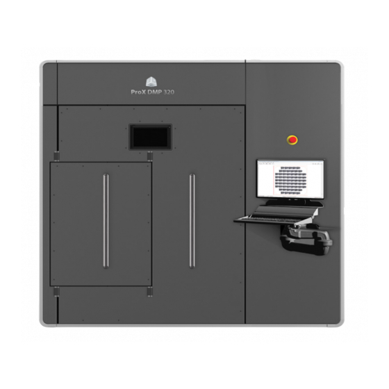
. Other advantages are the quick set up times and the ability to produce very complex assemblies as a single part . The ProX DMP320 has a build platform of 275 x 275 x 420mm (including printing plate) which can produce big and high quality parts in a variety of metals . The machine features easy cleaning and rapid material switching . -
Page 6: Safety Guidelines And Instructions
Certified service personnel • are those who have completed the 3D Systems service training package and are certified to perform service tasks. Certification may occur at various levels, and servicers should only perform tasks they are authorized and certified to complete. -
Page 7: Safety Symbols And Definitions
When working in areas where reactive metal condensates are present, use fire retardant special fabric, rendered conductive, trousers without turn-ups, closed pockets . Harmful Irritant Warning: Indicates that eyes and skin irritation could result while exposed to chemical composition . 3D SYSTEMS, INC. -
Page 8: First Aid Section- What To Do
• Any other pertinent information Please send this information to 3D Systems within a day of the accident . Electrocution The DMP system contains equipment energized at 400 volts . Do not attempt to remove protective panels . There are no user serviceable parts inside . -
Page 9: Safety Interlocks
Print will not start • Warning message appears on DMP system display • Valves are closed • Argon/ Pressurized air supply are closed • Print module movements are disabled • Vacuum pump/blower are disabled • Red stack light blinks on/off 3D SYSTEMS, INC. -
Page 10: Limited Access And Barrier Shielding
When operating any DMP equipment, keep the following electrical safety points in mind: • Only 3D Systems certified service personnel should operate DMP equipment with access panels or service doors open. • Heed high voltage warning signs and labels . -
Page 11: Personal Protective Equipment
• Dedicated grounding points in each process room • Antistatic flooring or Antistatic floor mats In addition it is recommended to check the grounding itself on a regular basis in accordance to local regulations . 3D SYSTEMS, INC. -
Page 12: Vacuum Cleaners
MATERIAL SAFETY All materials certified by 3D Systems are safe during normal operation. However, you should be aware of the following issues: • Any material, material-like substance, or airborne cloud of material has a remote chance of rapid combustion . -
Page 13: Finding Material Safety Information
WARNING: THE OPERATOR MUST USE AN APPROVED VACUUM CLEANER TO CLEAN UP EXCESS MATERIAL . 3D SYSTEMS RECOMMENDS AN EXPLOSION-PROOF MODEL . CONTACT 3D SYSTEMS CUSTOMER SERVICE FOR PURCHASING OPTIONS . Finding Material Safety Information Use the Material Safety Information table to locate references and contacts for information on important material safety topics . Read the SDS of the material used for the specific precautions to be observed. -
Page 14: Potentially Hazardous Metal Powders
Material Handling Precautions Always wear all PPE as specified in the section, “Personal Protective Equipment”. Read the SDS of the material used for the specific precautions you should observe. Use the following table of precautions as a general guide 3D SYSTEMS, INC. -
Page 15: Safe Material Handling Guidelines
Give operators access to the SDS’s that apply to materials they will be handling and ensure that they read them . If necessary, translate them . • File SDS’s in an easily accessible location for immediate reference. • Strictly follow all the conditions in each SDS . 3D SYSTEMS, INC. -
Page 16: Argon Safety
. 3D Systems recommends that you have an oxygen monitor installed in the room containing the DMP system . This monitor will alert you if the oxygen level drops below a designated point . It must be wired to trigger an immediate shutdown of the DMP system and any inert gas flow. -
Page 17: Risk Relating To Gas Bottles
. The laser safety window conforms to standard CE EN207 allowing operators to observe interaction of laser and material while avoiding the risk of burns and loss of visual acuity . 3D SYSTEMS, INC. -
Page 18: Safety Labels On The Dmp System
SAFETY LABELS ON THE DMP SYSTEM Voltage, Compliance and Id Labels Laser Certification / Identification 3D SYSTEMS, INC. -
Page 19: Tip Over Warning Label - Process Chamber Door
Tip Over Warning Label - Process Chamber Door Burn Hazard Label - Back of Process Chamber . Adjacent to Oxygen Sensor . 3D SYSTEMS, INC. -
Page 20: Safety Label - Pinch Point
Pinch point label –build module Laser Safety Labels - Located on Scanner . Left and Right Side of Lens Cover 3D SYSTEMS, INC. -
Page 21: Laser Safety Labels - Located On Door And Top Cover
Laser Safety Labels - Located on Door 3D SYSTEMS, INC. -
Page 22: European Directives
This section lists all of the equipment that is provided as a part of the ProX DMP 320. For more detail on product specification, please refer to the ProX DMP 320 Facility Guide . • Process Chamber/Electrical Cabinet • Vacuum Pump • Blower • Filter • Chiller • Transport Cart • Sieving Station (optional) 3D SYSTEMS, INC. -
Page 23: Prox Dmp320 At A Glance
PROX DMP320 AT A GLANCE PROX DMP320 SYSTEM COMPONENTS Process Chamber Door The door makes an airtight seal with the process chamber and protects the operator from the laser . Process Chamber Window This enable the operator to look inside the process chamber while being protected from the laser . - Page 24 When this switch is turned on with the key the laser can be turned on even when the pressure or oxygen levels are not at the required level. Note: the laser will still be turned off by opening the door. This should only be used by 3D Systems certified maintenance personnel to calibrate the laser system .
- Page 25 It can be removed and “swapped-out” for another build module which contains a different metal powder. Locking Pins The locking pins lock the build module into place and maintain it in the correct position . These must be unlocked to pull the module in its outward position or to remove it . 3D SYSTEMS, INC.
- Page 26 Carries all power and signal connections from the process chamber to the build module . Overflow Container Holds the excess powder until it can be extracted and sieved for re-use . Overflow Chute Powder deposited in here is lead to the overflow containers. 3D SYSTEMS, INC.
- Page 27 The sieving station allows the user to electronically sift and separate material from the overflow bins and separate it into the waste and the usable material that can be fed into the feeds to build parts . 3D SYSTEMS, INC.
-
Page 28: Software Overview
PC and other high performance stations that run DMP worker . The different packages are intelligently divided among all the running DMP workers on the network . 3D SYSTEMS, INC. - Page 29 . When finished the output will be placed on the location of the original .stl file. You can also find a link to this location on the bottom left corner of the screen . 3D SYSTEMS, INC.
-
Page 30: Dmp Control
Centrally manage your serial manufacturing jobs . • All with Traceability and Version Control • SaveJob: Saves the job as a .lmj file • CloseJob: closes the job • Base plate: Lets the user change the printing plate size 3D SYSTEMS, INC. - Page 31 Move (toggle button): Turn move group mode on/off If it is turned on, you can drag your groups manually to the desired position . • Process Job: Start printing the job, this will only be enabled on the machine pc . 3D SYSTEMS, INC.
-
Page 32: Preview Screen
Preview screen • Shows a preview of the current selected layer for each part A Calibrated scan area B . Printing plate C . Selected layer of part to be printed D . Build platform 3D SYSTEMS, INC. -
Page 33: Tools Panel
The layers can also be scrolled trough by using the up / down arrow keys Move/copy groups via this window you can accurately place parts and by clicking one of the buttons while holding CTRL you create new clones of the selected groups at the new location . Units is millimeters 3D SYSTEMS, INC. -
Page 34: Update Scanner Calibration File
Download the latest version of the calibration file, e.g. D2_1224_LM45_v04.ct5 Copy this file to your machine and copy it into the folder C:\3D Systems\Config\Machines\LM45 Make you place the file in the correct sub folder, (LMxx where xx is your machine serial number). -
Page 35: Traceability Of Slicing/Hatching Parameters
Click on the far left bar to switch to the properties windows . Select group . Select part . In the part property window locate the field ‘SliceSettings’. This will list the slice settings used to generate this part . 3D SYSTEMS, INC. -
Page 36: Building Very Clise To The Platform Boarders
Move the scanner to the requested ‘test’ location and verify it is inside the printing plate. If the spot is not inside the printing plate, shift your part in DMP Control to match the real position . 3D SYSTEMS, INC. -
Page 37: Configure Automatic Job File Backup
The job folders will be placed in this directory . Click Save and restart DMP Control and DMP Deposition . You can test access to the job storage folder (after software restart) via: DMP Control > menu Admin > Open job storage network folder… 3D SYSTEMS, INC. -
Page 38: Options For The Materialbatchnumberformatmask Setting
A-kr A-KR \LW->AA-######## LW-_-_____ Fixed letters “LW”, followed by dash -, then 2 letters (that are converted to capitals automatically via the ‘>’ option, then dash -, then 8 digits (not more, LW-TI-20151005 not less) . LW-XY-12345678 3D SYSTEMS, INC. - Page 39 0. $999,999 .00 A currency value in the range of 0 to 999999 . The currency, thousandth, and decimal characters will be replaced at run time with their culture-specific equivalents. 3D SYSTEMS, INC.
-
Page 40: Configure E-Mail Notifications
Click Save configuration to permanently save it on the DMP Server, making it available for all machines in your facility. Make sure you add the sender addresses to your safe senders list in your e-mail program and check the SPAM folder in the beginning . 3D SYSTEMS, INC. -
Page 41: Dmp Deposition
(parts per million) when the oxygen content gets lower . This will be shown as soon as the printer starts preparing to print . Next to that is the relative pressure in the process chamber (in millibar) . A negative number means there is underpressure, a positive number overpressure 3D SYSTEMS, INC. -
Page 42: Manual Operation
3D SYSTEMS, INC. -
Page 43: Feed/Build Platform Movements
Tip: When the shift button is held while pressing one of the buttons of a feed platform, both feed platforms will perform the same action . Actions Prepares the printer to start printing . Releases the pressure from the process chamber, This allows the user to open the door and unload the build . 3D SYSTEMS, INC. -
Page 44: Actuators
By pressing the button on the right this screen opens up and shows all currently engaged actuators Sensors By pressing the button on the right this screen opens up and shows all current sensor data Machine preparation checklist When you press the “prepare for job start” button the following checklist pop’s up: 3D SYSTEMS, INC. -
Page 45: Run Job
Keep coater at home positions: With this option set the coater will go to its endposition and wait there after each powder deposition . When this option is not set, the coater will go the end position after deposition and then go back to between the building platform and the feed to wait for the next deposition cycle . 3D SYSTEMS, INC. -
Page 46: Status
Maintenance tasks in the near future Maintenance tasks in the further future Operator: Maintenance -> Must be performed by 3d Systems certified maintenance personnel Production -> Must be performed by production operator Description: Short description about the maintenance task Info link: Opens up the applicable work instruction for the maintenance task . -
Page 47: Background Programs
This will also manage DMP software updates • Must be manually run when starting up the DMP Server/user PC . DMP Slicer • Performs splicing for DMP explorer DMP HatchWise 2 • Performs hatching for DMP explorer 3D SYSTEMS, INC. -
Page 48: Dmp Server
Never bring the ProX DMP 320 machines into a domain . If the machines and the DMP Server are in a different domain or VLAN, your IT administrator needs to ensure both machines can access each other . 3D SYSTEMS, INC. -
Page 49: System Use
Make sure the emergency stop located on the front of the machine is not engaged Press the “reset emergency stop.” Press the “pc on” button to turn the pc on. Start DMP Deposition (7) and DMP Control (8) . The printer is now ready to be used . 3D SYSTEMS, INC. -
Page 50: Shutting Printer Down
(3) . Turn off the Main Power (4) . CAUTION: Do not turn off the 24 Volts before shutting down DMP deposition . CAUTION: Do not turn off the main power before shutting down the computer . 3D SYSTEMS, INC. -
Page 51: Preparing Prox Dmp 320
. It is also advised that the vacuum dust extractor be over top of the bin . CAUTION: The print plate must be compatible with the print material . 3D SYSTEMS, INC. - Page 52 . Clean the printing plate using 91% isopropyl alcohol before installing it into the printer . Place the printing plate into position and secure each corner of the printing plate with an M6 bolt . 3D SYSTEMS, INC.
- Page 53 Manual operation screen . Remove the recoater housing from the recoater bridge by releasing 2 bolts . Place new silicone strip in the recoater housing . Tighten all the bolt and ensure the silicone strip is fixed. 3D SYSTEMS, INC.
- Page 54 11 . Re-attach recoater housing to recoater bridge . 12 . Move the coater to one of the far sides (1) and move the powder feed from that side up (2) until the powder is above the module level by a few millimetres 3D SYSTEMS, INC.
- Page 55 10’s of micrometers at a time. Try to not go to far up because when the recoater scrapes on the build platform, the silicone strip will get damaged and needs to be replaced . 16. Pictured here are examples of what’s good (2) and what’s considered not good (3). 3D SYSTEMS, INC.
- Page 56 Use manual operation to move the powder surface of the feeds to just above the module top . Make sure you do not move the build platform. Use the recoater to make a flat equal powder bed . (5) 3D SYSTEMS, INC.
- Page 57 Higher volume parts need more powder, e .g . up to 320% . 27 . Open the job you want to process by double-clicking on DMP control (6) on the desktop . 28 . Open the applicable job (7) . 29 . Click on job analyzer . 3D SYSTEMS, INC.
- Page 58 . (12) 34 . Make sure Single Layer and PowerBurn (13) are no longer on . You can now start the job from layer 1 and the printer will start with the direct metal printing . 3D SYSTEMS, INC.
-
Page 59: Removing Printed Parts From Printer
Move the two feeds until the powder is at the height of the top of module . Set the User position of the 2 feeds to 0 by clicking on “User position” and setting it to 0. This will mark till where the unused powder goes . 3D SYSTEMS, INC. - Page 60 Continue moving the build platform up 20 mm at a time, lowering the feeds with steps of 100 mm when needed and brushing away the powder until you have most of the visible powder removed as shown . 3D SYSTEMS, INC.
- Page 61 12 . Lift platform up at an angle and let excess powder fall into bin as shown . 13 . Continue removing the excess powder by tapping the back of the print platform with a rubber mallet . 3D SYSTEMS, INC.
-
Page 62: Purging Used Material
. Repeat steps 1-3 for the opposite side . Move the airflow nozzle up and out of the way. Check if the stops are down and operating . 3D SYSTEMS, INC. - Page 63 10. Flip the handle and let the old material flow into the bin. 11. When material quits, flip the handle to the closed position . 12 . Do this for both sides . 13 . Use a sieving system to sift the usable material for the next job . 3D SYSTEMS, INC.
-
Page 64: Sieving Station (Optional)
. Press the green start button (3) . Set the timer . The timer can be set between 0 and 10 hrs depending on the amount of powder to be sieved . 3D SYSTEMS, INC. - Page 65 (7) . When the bin is full, push the bin up and turn the other way until you can move the bin completely down and away . The powder in the bin can now be poored in the feeds to be re-used . 3D SYSTEMS, INC.
-
Page 66: Sieving System Maintenance
Loosen the hatch (1) by turning the levers (2) until the latch can be opened . Loosen the levers on the end (2) and remove the end (3) as shown . CAUTION: This piece is heavy, handle with care . Carefully slide out cyclone screener out of receptacle . 3D SYSTEMS, INC. - Page 67 . This will get tightened down in the last step . Repeat Steps 4 and 5 for the other side . Secure screens by tightening up bars on rings with an adjustable wrench . 3D SYSTEMS, INC.
- Page 68 . Unscrew the top of the water lock bottle, remove the water and poor 300ml regular tap water in . Screw the top of the water bottle back on and make sure the glass outlet tube inside the bottle comes to the 100ml mark . 3D SYSTEMS, INC.
-
Page 69: Maintenance
Locking the module cart to process chamber by turning the wheel clockwise, until the module cart is locked . Now slide the module on the cart and start turning the wheel counter clockwise until the module is fixed on the cart. 3D SYSTEMS, INC. - Page 70 Unhook the 24V supply cables, always make sure the 24V supply is shut down first. Clean the complete inside of the process chamber using paper towels with isopropyl alcohol . 3D SYSTEMS, INC.
-
Page 71: Material Change: Changing Powder In A Build Module
10 . If Build Module 1 is to remain unused for an extended period of time, (over one week), remove all of the material from Build Module 1 as described the the previous procedure. Store the material as described in the section, “Material Safety”, in this document. 3D SYSTEMS, INC. -
Page 72: Clean Laser Window
. This way, most of the dust is already removed . Take a white optics cleaning cloth and form a small ball, as shown . Spray the cloth multiple times with the Optics Cleaning Fluid . 3D SYSTEMS, INC. - Page 73 Check to see if the window is clean . To check if window is clean take an LED flashlight and move the light into different angles to see of there are any streaks and/or dust left on the window . 3D SYSTEMS, INC.
-
Page 74: Door Seal And Door Bolts
. Cut the ends of the seal straight and glue together with super glue . Be careful not to use too much glue, this will make the rubber hard . 3D SYSTEMS, INC. -
Page 75: Clean Overpressure Valve
The chiller has a fluid capacity of 5 liters (1.3 gallons). It requires a mixture of one pint of OptiShield (p/n 110362-00) to one gallon of distilled water (p/n 9208-30021) . 3D SYSTEMS, INC. -
Page 76: Cleaning The Chiller Air Vent And Changing The Air Vent Filter
Refer to the OEM documentation for detailed instructions . Drain Filter Replacement When the chiller is free of fluids, open the drain filter housing at the rear of the chiller and uninstall/reinstall a Pentek CW-F Polypropylene Wound Filter (Scott Equipment #155186-43). 3D SYSTEMS, INC. -
Page 77: Troubleshooting
If you cannot access the DMP Server, no DMP software program will work correctly . Contact your local IT administrator to set up the correct access, The default DMPserver login details are: • User name: LM • Password: DMPuser 3D SYSTEMS, INC. -
Page 78: Reinstall Or Restore A Broken Dmp Server Computer
To have the DMP Worker and DMP Remoting Server programs started automatically when you log on to Windows; you can copy/drag these shortcuts from desktop into the Windows Startup folder: Windows Start > All Programs > Startup 3D SYSTEMS, INC. -
Page 79: Dmp Explorer
. Try with other DMP Slicer parameter set: • Expand the “processing options” in DMP Explorer, by clicking the arrow button . • Then select “DMP Slicer set” = 0 [no filtering] or 3 [lower accuracy]’. 3D SYSTEMS, INC. - Page 80 In case previous steps keep failing, you can try to slice the part first with modified slicing parameters. To do this: • Start DMP Slicer (C:\3D Systems\DMP Slicer\DMP Slicer.exe) • Set the correct layer thickness and modify the slicer parameters •...
- Page 81 . Right click on the DMP Worker icon in the system tray . Click Set Max Processes and set to a lower value The new setting will take effect the next time DMP Worker is started . 3D SYSTEMS, INC.
-
Page 82: Dmp Deposition
‘Run job’ button can be pressed. If this detection failed during program start, go to menu Controllers > Verify if ready for processing . This will repeat the evaluation . After successful verification, you can press the ‘Run job’ button again. 3D SYSTEMS, INC. - Page 83 3D Systems, Inc . 333 Three D Systems Circle | Rock Hill, SC | 29730 www .3dsystems .com ©2016 3D Systems, Inc . All rights reserved . P/N 15-D20, Rev . A 3D SYSTEMS, INC.
Need help?
Do you have a question about the ProX DMP320 and is the answer not in the manual?
Questions and answers