Table of Contents
Advertisement
Quick Links
Pos: 2 /Dokumentation allgemein/Einband/Einband Deckblatt @ 9\mod_1285229289866_0.doc @ 64941 @ @ 1
Manual
WAGO-I/O-SYSTEM 750
ETHERNET Programmable Fieldbus Controller
750-880, 750-880/025-000
10 / 100 Mbit/s; digitale und analoge Signale
Version 1.0.1
Pos: 3 /Alle Serien (Allgemeine Module)/Hinweise zur Dokumentation/Impressum - allgemeine Angaben, Anschriften, Telefonnummern und E-Mail-Adressen @ 3\mod_1219151118203_21.doc @ 21060 @ @ 1
Advertisement
Chapters
Table of Contents

Related Manuals for WAGO 750-880


Summary of Contents for WAGO 750-880
- Page 1 Manual WAGO-I/O-SYSTEM 750 ETHERNET Programmable Fieldbus Controller 750-880, 750-880/025-000 10 / 100 Mbit/s; digitale und analoge Signale Version 1.0.1 Pos: 3 /Alle Serien (Allgemeine Module)/Hinweise zur Dokumentation/Impressum - allgemeine Angaben, Anschriften, Telefonnummern und E-Mail-Adressen @ 3\mod_1219151118203_21.doc @ 21060 @ @ 1...
- Page 2 WAGO-I/O-SYSTEM 750 750-880, 750-880/025-000 ETHERNET Programmable Fieldbus Controller © 2011 by WAGO Kontakttechnik GmbH & Co. KG All rights reserved. WAGO Kontakttechnik GmbH & Co. KG Hansastraße 27 D-32423 Minden Phone: +49 (0) 571/8 87 – 0 Fax: +49 (0) 571/8 87 – 1 69 E-Mail: info@wago.com...
-
Page 3: Table Of Contents
WAGO-I/O-SYSTEM 750 Table of Contents 750-880, 750-880/025-000 ETHERNET Programmable Fieldbus Controller Pos: 5 /Dokumentation allgemein/Verzeichnisse/Inhaltsverzeichnis - Überschrift 1 und Verzeichnis @ 3\mod_1219151230875_21.doc @ 21063 @ @ 1 Table of Contents Notes about this Documentation............... 12 Validity of this Documentation............... 12 Copyright.................... - Page 4 Table of Contents WAGO-I/O-SYSTEM 750 750-880, 750-880/025-000 ETHERNET Programmable Fieldbus Controller 4.2.2 Fieldbus Connection................47 Display Elements ..................49 Operating Elements ................. 51 4.4.1 Service Interface................. 51 4.4.2 Mode Selector Switch................. 52 4.4.3 Address Selection Switch ..............54 4.4.4 Memory Card Slot ................54 4.4.4.1...
-
Page 5: Table Of Contents
WAGO-I/O-SYSTEM 750 Table of Contents 750-880, 750-880/025-000 ETHERNET Programmable Fieldbus Controller 7.3.2 Addressing..................87 7.3.2.1 Addressing of I/O Modules ............88 7.3.2.2 Address Ranges ................89 7.3.2.3 Absolute Addressing..............92 7.3.3 Data Exchange between MODBUS/TCP Master and I/O Modules... 94 7.3.3.1... - Page 6 Table of Contents WAGO-I/O-SYSTEM 750 750-880, 750-880/025-000 ETHERNET Programmable Fieldbus Controller 9.6.2 Transfer via Fieldbus and ETHERNET ........... 159 Configuring via the Web-Based Management System (WBM)... 161 10.1 Information.................... 161 10.2 Ethernet ....................163 10.3 TCP/IP....................166 10.4 Port ......................167 10.5...
-
Page 7: Table 192: Message Router
WAGO-I/O-SYSTEM 750 Table of Contents 750-880, 750-880/025-000 ETHERNET Programmable Fieldbus Controller 12.2.3.1 Function Code FC1 (Read Coils) ..........224 12.2.3.2 Function Code FC2 (Read Input Discretes)......... 226 12.2.3.3 Function Code FC3 (Read Multiple Registers) ......228 12.2.3.4 Function Code FC4 (Read Input Registers)......... 229 12.2.3.5... -
Page 8: Table 280: Input Fieldbus Variable Usint Extended
Table of Contents WAGO-I/O-SYSTEM 750 750-880, 750-880/025-000 ETHERNET Programmable Fieldbus Controller 12.3.5.26 Analog Output Point Extended 1 (6C )........292 12.3.5.27 Analog Output Point Extended 2 (70 ) ........293 12.3.5.28 Analog Output Point Extended 3 (74 ) ........294 12.3.5.29... - Page 9 WAGO-I/O-SYSTEM 750 Table of Contents 750-880, 750-880/025-000 ETHERNET Programmable Fieldbus Controller 13.2.4.2 4 Channel Analog Output Modules ..........323 13.2.5 Specialty Modules ................324 13.2.5.1 Counter Modules ................. 324 13.2.5.2 Pulse Width Modules..............326 13.2.5.3 Serial Interface Modules with alternative Data Format....326 13.2.5.4...
- Page 10 Table of Contents WAGO-I/O-SYSTEM 750 750-880, 750-880/025-000 ETHERNET Programmable Fieldbus Controller 13.3.4.1 2 Channel Analog Output Modules ..........350 13.3.4.2 4 Channel Analog Output Modules ..........350 13.3.5 Specialty Modules ................351 13.3.5.1 Counter Modules ................. 351 13.3.5.2 Pulse Width Modules..............353 13.3.5.3...
-
Page 11: Table Of Contents
WAGO-I/O-SYSTEM 750 Table of Contents 750-880, 750-880/025-000 ETHERNET Programmable Fieldbus Controller 16.2.2 Product Group .................. 388 16.2.3 Versions Group................. 389 16.2.4 Real-Time Clock Group ..............390 16.2.5 Ethernet Group ................. 391 16.2.6 Actual Error Group................391 16.2.7 PLC Project Group ................392 16.2.8... -
Page 12: Notes About This Documentation
Care must also be taken to ensure that any supplement to these instructions are included, if applicable. Pos: 10 /Serie 750 (WAGO-I/O-SYSTEM)/Hinweise zur Dokumentation/Gültigkeitsbereich Dokumentation Koppler/Controller 750-xxxx, ohne Variantenangabe @ 4\mod_1239095911562_21.doc @ 30110 @ 2 @ 1 Validity of this Documentation This documentation is only applicable to the device: "ETHERNET Programmable Fieldbus Controller"... -
Page 13: Symbols
WAGO-I/O-SYSTEM 750 Notes about this Documentation 750-880, 750-880/025-000 ETHERNET Programmable Fieldbus Controller Pos: 12.3 /Alle Serien (Allgemeine Module)/Hinweise zur Dokumentation/Symbole @ 3\mod_1217394197593_21.doc @ 21010 @ 2 @ 1 Symbols Personal Injury! Indicates a high-risk, imminently hazardous situation which, if not avoided, will result in death or serious injury. -
Page 14: 750-880, 750-880/025-000 Ethernet Programmable Fieldbus Controller
Notes about this Documentation WAGO-I/O-SYSTEM 750 750-880, 750-880/025-000 ETHERNET Programmable Fieldbus Controller Additional Information: Refers to additional information which is not an integral part of this documentation (e.g., the Internet). Pos: 12.4 /Dokumentation allgemein/Gliederungselemente/---Seitenwechsel--- @ 3\mod_1221108045078_0.doc @ 21810 @ @ 1 Manual Version 1.0.1... -
Page 15: Number Notation
WAGO-I/O-SYSTEM 750 Notes about this Documentation 750-880, 750-880/025-000 ETHERNET Programmable Fieldbus Controller Pos: 12.5 /Alle Serien (Allgemeine Module)/Hinweise zur Dokumentation/Zahlensysteme @ 3\mod_1221059454015_21.doc @ 21711 @ 2 @ 1 Number Notation Table 1: Number Notation Number code Example Note Decimal Normal notation... -
Page 16: Important Notes
All changes to the coupler or controller should always be carried out by qualified personnel with sufficient skills in PLC programming. Pos: 15.5 /Serie 750 (WAGO-I/O-SYSTEM)/Wichtige Erläuterungen/Bestimmungsgemäße Verwendung 750-xxxx @ 3\mod_1224064151234_21.doc @ 24070 @ 3 @ 1 2.1.3 Use of the 750 Series in Compliance with Underlying... -
Page 17: Technical Condition Of Specified Devices
The components to be supplied Ex Works, are equipped with hardware and software configurations, which meet the individual application requirements. WAGO Kontakttechnik GmbH & Co. KG will be exempted from any liability in case of changes in hardware or software as well as to non-compliant usage of components. -
Page 18: Safety Advice (Precautions)
All power sources to the device shall be switched off prior to performing any installation, repair or maintenance work. Pos: 15.10.2 /Serie 750 (WAGO-I/O-SYSTEM)/Wichtige Erläuterungen/Sicherheitshinweise/Gefahr/Gefahr: Einbau 0750-xxxx nur in Gehäusen, Schränken oder elektrischen Betriebsräumen! @ 6\mod_1260180556692_21.doc @ 46731 @ @ 1 Installation only in appropriate housings, cabinets or in electrical operation rooms! The WAGO-I/O-SYSTEM 750 and its components are an open system. -
Page 19: 750-880, 750-880/025-000 Ethernet Programmable Fieldbus Controller
WAGO-I/O-SYSTEM 750 Important Notes 750-880, 750-880/025-000 ETHERNET Programmable Fieldbus Controller Do not use any contact spray! Do not use any contact spray. The spray may impair contact area functionality in connection with contamination. Pos: 15.11.5 /Alle Serien (Allgemeine Module)/Wichtige Erläuterungen/Sicherheitshinweise/Achtung/Achtung: Verpolung vermeiden! @ 6\mod_1260184045744_21.doc @ 46767 @ @ 1... -
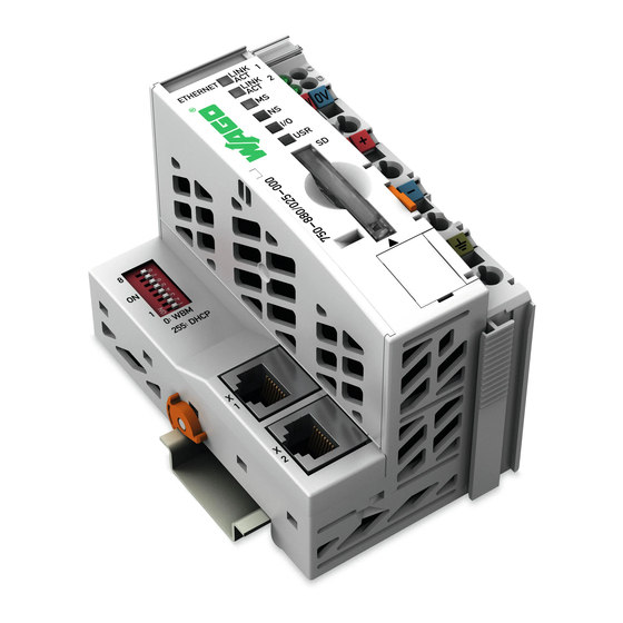
Page 20: System Description
Figure 1: Fieldbus node Couplers/controllers are available for different fieldbus systems. Pos: 17.3 /Serie 750 (WAGO-I/O-SYSTEM)/Systembeschreibung/Gerät und System/Systembeschreibung - Beschreibung Aufbau Feldbusknoten (Standard + erweiterter ECO) @ 3\mod_1231493221890_21.doc @ 25870 @ @ 1 The standard couplers/controllers and extended ECO couplers contain the fieldbus interface, electronics and a power supply terminal. -
Page 21: Manufacturing Number
(if available) and further internal information for WAGO Kontakttechnik GmbH & Co. KG. Pos: 17.7 /Serie 750 (WAGO-I/O-SYSTEM)/Systembeschreibung/Gerät und System/Hardware-Adresse (MAC-ID) @ 7\mod_1270708464299_21.doc @ 54960 @ 2 @ 1 Hardware Address (MAC ID) Each ETHERNET Programmable Fieldbus Controller has a unique and internationally unambiguous physical address, referred to as the MAC-ID (Media Access Control Identity). -
Page 22: Component Update
The original manufacturing data on the housing of the component remain thereby. Pos: 17.10 /Serie 750 (WAGO-I/O-SYSTEM)/Systembeschreibung/Gerät und System/Lagerung, Kommissionierung und Transport @ 3\mod_1225446600609_21.doc @ 24897 @ 2 @ 1 Storage, Assembly and Transport Wherever possible, the components are to be stored in their original packaging. -
Page 23: Power Supply
(internal bus, logic) and the field electronics. Some digital and analog input modules have each channel electrically isolated, please see catalog. Pos: 17.13.3 /Serie 750 (WAGO-I/O-SYSTEM)/Systembeschreibung/Versorgung/Potentialtrennung - Bild (Standard + erweiterter ECO) @ 3\mod_1232950095187_21.doc @ 26740 @ @ 1 Figure 3: Isolation for Standard Couplers/Controllers and extended ECO Couplers Pos: 17.13.4 /Serie 750 (WAGO-I/O-SYSTEM)/Systembeschreibung/Versorgung/Potentialtrennung - Hinweis: Schutzleiterfunktion sicherstellen (Ringspeisung) @ 3\mod_1232950095703_21.doc @ 26744 @ @ 1... -
Page 24: System Supply
The use of an incorrect supply voltage or frequency can cause severe damage to the component. Pos: 17.13.8 /Serie 750 (WAGO-I/O-SYSTEM)/Systembeschreibung/Versorgung/Systemversorgung - Anschluss - Systemversorgung (Standard + erweiterter ECO) @ 3\mod_1232950104031_21.doc @ 26776 @ @ 1 Figure 4: System supply for standard coupler/controller and extended ECO couplers Pos: 17.13.9 /Serie 750 (WAGO-I/O-SYSTEM)/Systembeschreibung/Versorgung/Systemversorgung - Anschluss - Die eingespeiste 24 V-Gleichspannung versorgt... -
Page 25: Alignment
750-880, 750-880/025-000 ETHERNET Programmable Fieldbus Controller Figure 5: System voltage for standard couplers/controllers and extended ECO couplers Pos: 17.13.11 /Serie 750 (WAGO-I/O-SYSTEM)/Systembeschreibung/Versorgung/Systemversorgung - Anschluss - Hinweis: Gleichz. Rücksetzen aller Versorgungsmodule @ 3\mod_1232950097906_21.doc @ 26760 @ @ 1 Note Only reset the system simultaneously for all supply modules! Resetting the system by switching on and off the system supply, must take place simultaneously for all supply modules (coupler/controller and 750 613). -
Page 26: 750-880, 750-880/025-000 Ethernet Programmable Fieldbus Controller
Pos: 17.13.14 /Serie 750 (WAGO-I/O-SYSTEM)/Systembeschreibung/Versorgung/Beispiel: @ 3\mod_1232630417843_21.doc @ 26605 @ @ 1 Example: Pos: 17.13.15 /Serie 750 (WAGO-I/O-SYSTEM)/Systembeschreibung/Versorgung/Systemversorgung - Auslegung - Beispiel 1 (erweiterter ECO) @ 3\mod_1232950106250_21.doc @ 26788 @ @ 1 Calculating the current consumption on an Example Coupler:... -
Page 27: 750-880, 750-880/025-000 Ethernet Programmable Fieldbus Controller
η = 0.87 (87 % Efficiency of the power supply at nominal load 24 V) Pos: 17.13.21 /Serie 750 (WAGO-I/O-SYSTEM)/Systembeschreibung/Versorgung/Systemversorgung - Auslegung - Hinweis: Bei Test der Stromaufnahme Ausgänge aktivieren @ 3\mod_1232950110750_21.doc @ 26812 @ @ 1 Note Activate all outputs when testing the current consumption! -
Page 28: Field Supply
From there a new power supply occurs which may also contain a new voltage potential. Pos: 17.13.29 /Serie 750 (WAGO-I/O-SYSTEM)/Systembeschreibung/Versorgung/Feldversorgung - Anschluss - 2 Hinweise: Potential neu einspeisen + Distanzklemme @ 3\mod_1232950091343_21.doc @ 26724 @ @ 1 Manual... -
Page 29: Fusing
Thus, you can prevent the results of wiring errors. Pos: 17.13.30 /Serie 750 (WAGO-I/O-SYSTEM)/Systembeschreibung/Versorgung/Feldversorgung - Absicherung @ 3\mod_1232950081500_21.doc @ 26692 @ 4 @ 1 3.6.3.2... -
Page 30: Figure 7: Supply Module With Fuse Carrier (Example 750-610)
System Description WAGO-I/O-SYSTEM 750 750-880, 750-880/025-000 ETHERNET Programmable Fieldbus Controller Figure 7: Supply module with fuse carrier (Example 750-610) NOTICE Observe the maximum power dissipation and, if required, UL requirements! In the case of power supply modules with fuse holders, you must only use fuses with a maximum dissipation of 1.6 W (IEC 127). -
Page 31: Figure 9: Opening The Fuse Carrier
WAGO-I/O-SYSTEM 750 System Description 750-880, 750-880/025-000 ETHERNET Programmable Fieldbus Controller Figure 9: Opening the fuse carrier Figure 10: Change fuse After changing the fuse, the fuse carrier is pushed back into its original position. Manual Version 1.0.1... -
Page 32: Figure 12: Fuse Modules For Automotive Fuses, Series 2006
System Description WAGO-I/O-SYSTEM 750 750-880, 750-880/025-000 ETHERNET Programmable Fieldbus Controller Alternatively, fusing can be done externally. The fuse modules of the WAGO series 281 and 282 are suitable for this purpose. Figure 11: Fuse modules for automotive fuses, series 282... -
Page 33: Supplementary Power Supply Regulations
WAGO-I/O-SYSTEM 750 System Description 750-880, 750-880/025-000 ETHERNET Programmable Fieldbus Controller Pos: 17.13.32 /Serie 750 (WAGO-I/O-SYSTEM)/Systembeschreibung/Versorgung/Ergänzende Einspeisungsvorschriften (Standard) @ 3\mod_1232950080218_21.doc @ 26684 @ 3 @ 1 3.6.4 Supplementary Power Supply Regulations The WAGO-I/O-SYSTEM 750 can also be used in shipbuilding or offshore and onshore areas of work (e. -
Page 34: Supply Example
You should separate the system supply and the field supply in order to ensure bus operation in the event of a short-circuit on the actuator side. Pos: 17.13.35 /Serie 750 (WAGO-I/O-SYSTEM)/Systembeschreibung/Versorgung/Versorgungsbeispiel - Information: Weitere Information zum Aufbau einer Ringspeisung @ 7\mod_1275469176935_21.doc @ 57340 @ @ 1 Additional information about the ring feeding In order to increase the system security, a ring feeding of the earth potential is recommended. -
Page 35: Figure 16: Supply Example For Standard Couplers/Controllers And Extended Eco Couplers
WAGO-I/O-SYSTEM 750 System Description 750-880, 750-880/025-000 ETHERNET Programmable Fieldbus Controller 750-400 750-410 750-401 750-613 750-616 750-612 750-512 750-512 750-513 750-616 750-610 750-552 750-630 750-600 Shield (screen) bus Main ground bus System Supply 230V Field Supply 230V Field 1) Separation module... -
Page 36: Power Supply Unit
System Description WAGO-I/O-SYSTEM 750 750-880, 750-880/025-000 ETHERNET Programmable Fieldbus Controller Pos: 17.13.38 /Serie 750 (WAGO-I/O-SYSTEM)/Systembeschreibung/Versorgung/Netzgeräte @ 3\mod_1232950093484_21.doc @ 26728 @ 3 @ 1 3.6.6 Power Supply Unit The WAGO-I/O-SYSTEM 750 requires a 24 V direct current system supply with a maximum deviation of -15 % or +20 %. -
Page 37: Grounding
WAGO-I/O-SYSTEM 750 System Description 750-880, 750-880/025-000 ETHERNET Programmable Fieldbus Controller Pos: 17.13.40 /Serie 750 (WAGO-I/O-SYSTEM)/Systembeschreibung/Versorgung/Erdung @ 3\mod_1231246555687_21.doc @ 25802 @ 234433 @ 1 Grounding 3.7.1 Grounding the DIN Rail 3.7.1.1 Framework Assembly When setting up the framework, the carrier rail must be screwed together with the electrically conducting cabinet or housing frame. -
Page 38: Grounding Function
System Description WAGO-I/O-SYSTEM 750 750-880, 750-880/025-000 ETHERNET Programmable Fieldbus Controller 3.7.2 Grounding Function The grounding function increases the resistance against disturbances from electro- magnetic interferences. Some components in the I/O system have a carrier rail contact that dissipates electro-magnetic disturbances to the carrier rail. -
Page 39: Grounding Protection
WAGO-I/O-SYSTEM 750 System Description 750-880, 750-880/025-000 ETHERNET Programmable Fieldbus Controller 3.7.3 Grounding Protection For the field side, the ground wire is connected to the lowest connection terminals of the power supply module. The ground connection is then connected to the next module via the Power Jumper Contact (PJC). -
Page 40: Shielding (Screening)
System Description WAGO-I/O-SYSTEM 750 750-880, 750-880/025-000 ETHERNET Programmable Fieldbus Controller Pos: 17.13.42 /Serie 750 (WAGO-I/O-SYSTEM)/Systembeschreibung/Versorgung/Schirmung @ 3\mod_1231251994828_21.doc @ 25813 @ 23333 @ 1 Shielding (Screening) 3.8.1 General The shielding of the data and signal conductors reduces electromagnetic interferences thereby increasing the signal quality. Measurement errors, data transmission errors and even disturbances caused by overvoltage can be avoided. -
Page 41: Wago Shield (Screen) Connecting System
750-880, 750-880/025-000 ETHERNET Programmable Fieldbus Controller 3.8.4 WAGO Shield (Screen) Connecting System The WAGO Shield Connecting system includes a shield clamping saddle, a collection of rails and a variety of mounting feet. Together these allow many different possibilities. See catalog W4 volume 3 chapter 10. -
Page 42: Device Description
Pos: 20.8 /Serie 750 (WAGO-I/O-SYSTEM)/Gerätebeschreibung/Beschreibung/Feldbuskoppler/-controller/Einleitender Text/Die Feldbusansch. best. aus 2 Ports (RJ-45). Ein im PFC integ. Ethernet-Switch (881) (Controller) @ 7\mod_1273679028172_21.doc @ 56480 @ @ 1 The fieldbus connection consists of two ports (RJ-45). An ETHERNET switch integrated in the PFC, which is operated in the store and forward mode, connects those fieldbus ports with the CPU. -
Page 43: 750-880, 750-880/025-000 Ethernet Programmable Fieldbus Controller
DHCP or BootP can be used. Pos: 20.14 /Serie 750 (WAGO-I/O-SYSTEM)/Gerätebeschreibung/Beschreibung/Feldbuskoppler/-controller/Einleitender Text/Der Anwender kann Clients und Server über eine int. Socket-API ... (830,841,842,871,872,873,881,882) @ 6\mod_1255509705625_21.doc @ 42760 @ @ 1 The user can program clients and servers via an internal socket-API for all transport protocols (TCP, UDP, etc.) with functional modules. -
Page 44: Table 8: Compatibility
The compatibility to other storage media available in trade cannot be ensured. Pos: 20.20 /Serie 750 (WAGO-I/O-SYSTEM)/Gerätebeschreibung/Beschreibung/Feldbuskoppler/-controller/Einleitender Text/Informationen über die Konfiguration und den Status des Feldbuskn. (830,841,849,871,872,873,881,882) @ 6\mod_1255513139250_21.doc @ 42781 @ @ 1 By default, the controller’s built-in HTML pages contain information on the configuration and status of the PFC, and can be read using a normal web browser. -
Page 45: View
Pos: 23 /Alle Serien (Allgemeine Module)/Überschriften für alle Serien/Ansicht - Überschrift 2 @ 4\mod_1240984217343_21.doc @ 31958 @ 2 @ 1 View Pos: 24.1 /Serie 750 (WAGO-I/O-SYSTEM)/Gerätebeschreibung/Ansicht/Feldbuskoppler/-controller/Legende/Ansicht - allg. Einleitung für Koppler/Controller @ 4\mod_1238494230133_21.doc @ 29446 @ @ 1 The view below shows the three parts of the device: •... -
Page 46: Table 9: Legend To The View Ethernet Tcp/Ip Fieldbus Controller
750-880, 750-880/025-000 ETHERNET Programmable Fieldbus Controller Pos: 24.4 /Serie 750 (WAGO-I/O-SYSTEM)/Gerätebeschreibung/Ansicht/Feldbuskoppler/-controller/Legende/Ansicht - Legende zur Ansicht ETHERNET TCP/IP-Controller (750-880,881,882) - Tabellenkopf und Nr: 1 @ 7\mod_1266415064861_21.doc @ 50950 @ @ 1 Table 9: Legend to the View ETHERNET TCP/IP Fieldbus Controller... -
Page 47: Connectors
(approximately 328.08 feet) can be used. Pos: 29.4 /Serie 750 (WAGO-I/O-SYSTEM)/Gerätebeschreibung/Anschlüsse/Feldbuskoppler/-controller/Die Anschlussstelle ist so konzipiert, dass Einbau in einen 80 mm hohen Schaltschrank möglich ist. @ 5\mod_1245073401892_21.doc @ 35339 @ @ 1 The RJ-45 socket is physically lower, allowing the coupler to fit in an 80 mm high enclosure once connected. -
Page 48: Table 10: Rj-45 Connector And Rj-45 Connector Configuration
Device Description WAGO-I/O-SYSTEM 750 750-880, 750-880/025-000 ETHERNET Programmable Fieldbus Controller Table 10: RJ-45 Connector and RJ-45 Connector Configuration View Contact Signal TD + Transmit + TD - Transmit - RD + Receive + free free Figure 23: RD - Receive -... -
Page 49: Display Elements
LED’s can be divided into three groups: Table 11: Display Elements Fieldbus Status Color Meaning Pos: 32.4 /Serie 750 (WAGO-I/O-SYSTEM)/Gerätebeschreibung/Anzeigeelemente/Feldbuskoppler/-controller/Legende/Anzeigeelemente - Feldbusstatus ETHERNET-basiert, spezifischer Tabellenteil 'LINK ACT1,2' @ 5\mod_1253106696993_21.doc @ 41692 @ @ 1 LINK green indicates a connection to the physical network at port 1... -
Page 50: 750-880, 750-880/025-000 Ethernet Programmable Fieldbus Controller
Device Description WAGO-I/O-SYSTEM 750 750-880, 750-880/025-000 ETHERNET Programmable Fieldbus Controller More information about the LED Signaling Read the detailed description for the evaluation of the displayed LED-Signals in the chapter "Diagnostics" > "LED Signaling". Pos: 33 /Dokumentation allgemein/Gliederungselemente/---Seitenwechsel--- @ 3\mod_1221108045078_0.doc @ 21810 @ @ 1 Manual Version 1.0.1... -
Page 51: Operating Elements
Open the damper Configuration and Programming Interface Pos: 35.3 /Serie 750 (WAGO-I/O-SYSTEM)/Gerätebeschreibung/Bedienelemente/Feldbuskoppler/-controller/Achtung: Gerät muss spannungsfrei sein! (für Anschluss von 750-920) @ 4\mod_1239105946740_21.doc @ 30247 @ @ 1 Device must be de-energized! To prevent damage to the device, unplug and plug in the communication cable only when the device is de-energized! The 750-920 Communication Cable is connected to the 4-pole header. -
Page 52: Mode Selector Switch
Therefore, program or define all outputs, so that these switch to a safe mode at a program stop. Pos: 37.2 /Serie 750 (WAGO-I/O-SYSTEM)/Gerätebeschreibung/Bedienelemente/Feldbuskoppler/-controller/Hinweis: Definieren der Ausgänge für einen Programm-Stopp! (für Betriebsartenschalter mit WBM) @ 4\mod_1240571895008_21.doc @ 31297 @ @ 1 Note... -
Page 53: 750-880, 750-880/025-000 Ethernet Programmable Fieldbus Controller
WAGO-I/O-SYSTEM 750 Device Description 750-880, 750-880/025-000 ETHERNET Programmable Fieldbus Controller Note Mode selector switch position is negligible in software start/stop! The position of the mode selector switch is not important when starting or stopping the PFC application from WAGO-I/O-PRO. One of the following functions is active, depending in which of the three static positions "top", "center"... -
Page 54: Address Selection Switch
Figure 27: Address Selection Switch Pos: 39.3 /Serie 750 (WAGO-I/O-SYSTEM)/Gerätebeschreibung/Bedienelemente/Feldbuskoppler/-controller/Der 8-polige DIP-Schalter dient zum Einstellen derIP-Adresse + Tabelle: Bedeutung Schalterstellungen @ 6\mod_1263465071407_21.doc @ 47990 @ @ 1 The 8-pole DIP switch is used to set the IP address and to select the protocol for setting the IP address. -
Page 55: Inserting A Memory Card
750-880, 750-880/025-000 ETHERNET Programmable Fieldbus Controller Only use recommended memory cards! Use only the SD memory card available from WAGO (item no. 758-879/000-001) since it is suitable for industrial applications under difficult environmental conditions and for use in the fieldbus controller. -
Page 56: Removing The Memory Card
Device Description WAGO-I/O-SYSTEM 750 750-880, 750-880/025-000 ETHERNET Programmable Fieldbus Controller 4.4.4.2 Removing the Memory Card Use an activation tool or a screwdriver to open the transparent cover flap by folding it upwards. To remove the memory card, first press it into the slot. -
Page 57: Technical Data
Pos: 42 /Alle Serien (Allgemeine Module)/Überschriften für alle Serien/Technische Daten - Überschrift 2 @ 3\mod_1232967587687_21.doc @ 26924 @ 2 @ 1 Technical Data Pos: 43.1 /Serie 750 (WAGO-I/O-SYSTEM)/Gerätebeschreibung/Technische Daten/Feldbuskoppler/-controller/Technische Daten 750-0880 @ 9\mod_1286534697253_21.doc @ 65475 @ 33333 @ 1 4.5.1 Device Data Table 17: Technical data –... -
Page 58: Supply
Voltage drop at I < 1 V/64 modules max. Data contacts slide contact, hard gold plated 1.5 µm, self-cleaning Pos: 43.3 /Serie 750 (WAGO-I/O-SYSTEM)/Gerätebeschreibung/Technische Daten/Technische Daten Klimatische Umweltbedingungen m. erw. Tempbereich; 0...55°C/-20...+60°C/-20...+85°C @ 5\mod_1247658089120_21.doc @ 37606 @ 3 @ 1 Manual Version 1.0.1... -
Page 59: Climatic Environmental Conditions
– dust, caustic vapors or gases – ionization radiation Pos: 43.4 /Serie 750 (WAGO-I/O-SYSTEM)/Gerätebeschreibung/Technische Daten/Feldbuskoppler/-controller/Achtung: Verringerte Pufferzeit bei zu hoher Lagertemperatur! (bei Echtzeituhr) @ 8\mod_1278604366911_21.doc @ 59412 @ @ 1 NOTICE Reduced buffer time at high storage temperature! Ensure that the storage of devices with a real time clock at high temperatures leads to a reduced buffer time for the real time clock. -
Page 60: Mechanical Strength
Device Description WAGO-I/O-SYSTEM 750 750-880, 750-880/025-000 ETHERNET Programmable Fieldbus Controller 4.5.8 Mechanical strength Table 24: Technical data – Mechanical strength Vibration resistance acc. to IEC 60068-2-6 Comment to the vibration resistance: a) Type of oscillation: sweep with a rate of change of 1 octave per minute 10 Hz ... -
Page 61: Approvals
Pos: 48.3 /Dokumentation allgemein/Gliederungselemente/------Leerzeile------ @ 3\mod_1224662755687_0.doc @ 24460 @ @ 1 Pos: 49 /Serie 750 (WAGO-I/O-SYSTEM)/Gerätebeschreibung/Zulassungen/Zulassungen in Vorbereitung Feldbuskoppler/-controller 750-xxxx Schiff, ohne Variantenangabe @ 6\mod_1255592681734_21.doc @ 42823 @ @ 1 The following ship approvals are pending for 750-880, 750-880/025-000 fieldbus coupler/controller: Pos: 50 /Alle Serien (Allgemeine Module)/Zulassungen/Schiffszulassungen/GL (Germanischer Lloyd) Cat. -
Page 62: Standards And Guidelines
Pos: 53 /Alle Serien (Allgemeine Module)/Überschriften für alle Serien/Normen und Richtlinien - Überschrift 2 @ 4\mod_1242804031875_21.doc @ 33646 @ 2 @ 1 Standards and Guidelines Pos: 54 /Serie 750 (WAGO-I/O-SYSTEM)/Gerätebeschreibung/Normen und Richtlinien/EMV-Normen Feldbuskoppler/-controller750-xxxx, ohne Variantenangabe @ 5\mod_1245244309850_21.doc @ 35512 @ @ 1 750-880, 750-880/025-000 meets the following requirements on emission and immunity of interference: Pos: 55 /Alle Serien (Allgemeine Module)/Normen und Richtlinien/EMV CE-Störfestigkeit EN 61000-6-2: 2005 @ 4\mod_1242797655625_21.doc @ 33591 @ @ 1... -
Page 63: Assembly
Pos: 60 /Alle Serien (Allgemeine Module)/Überschriften für alle Serien/Montieren - Überschrift 1 @ 3\mod_1225446744750_21.doc @ 24900 @ 1 @ 1 Assembly Pos: 61.1 /Serie 750 (WAGO-I/O-SYSTEM)/Montieren/Einbaulage @ 3\mod_1225446818312_21.doc @ 24903 @ 2 @ 1 Installation Position Along with horizontal and vertical installation, all other installation positions are allowed. -
Page 64: 750-880, 750-880/025-000 Ethernet Programmable Fieldbus Controller
Note Increase total length using a WAGO internal data bus extension module! Using an internal data bus extension module from WAGO, you can increase the total length of the fieldbus node. In this type of configuration, you must connect a 750-627 Bus Extension End Module to the last module of the node. -
Page 65: Assembly Onto Carrier Rail
WAGO-I/O-SYSTEM 750 Assembly 750-880, 750-880/025-000 ETHERNET Programmable Fieldbus Controller Pos: 61.4 /Serie 750 (WAGO-I/O-SYSTEM)/Montieren/Montage auf Tragschiene @ 3\mod_1225447227234_21.doc @ 24906 @ 233 @ 1 Assembly onto Carrier Rail 5.3.1 Carrier Rail Properties All system components can be snapped directly onto a carrier rail in accordance with the European standard EN 50022 (DIN 35). -
Page 66: Wago Din Rail
210-196 35 x 7,5; 1 mm; aluminum; unslotted Pos: 61.5 /Serie 750 (WAGO-I/O-SYSTEM)/Montieren/Abstände @ 3\mod_1225448283750_21.doc @ 24920 @ 2 @ 1 Spacing The spacing between adjacent components, cable conduits, casing and frame sides must be maintained for the complete fieldbus node. -
Page 67: Assembly Sequence
DI4. Pos: 61.10 /Serie 750 (WAGO-I/O-SYSTEM)/Wichtige Erläuterungen/Sicherheitshinweise/Achtung/Achtung: Aneinanderreihen von Busklemmen nur bei offener Nut! @ 6\mod_1256193351448_21.doc @ 43417 @ @ 1 Assemble the I/O modules in rows only if the grooves are open! Please take into consideration that some bus modules have no or only a few power jumper contacts. -
Page 68: Inserting And Removing Devices
WAGO-I/O-SYSTEM 750 750-880, 750-880/025-000 ETHERNET Programmable Fieldbus Controller Pos: 61.13 /Serie 750 (WAGO-I/O-SYSTEM)/Montieren/Geräte einfügen und entfernen - Überschrift 2 @ 3\mod_1231768483250_21.doc @ 25950 @ 2 @ 1 Inserting and Removing Devices Pos: 61.14 /Serie 750 (WAGO-I/O-SYSTEM)/Wichtige Erläuterungen/Sicherheitshinweise/Gefahr/Gefahr: Vorsicht bei der Unterbrechung von FE! @ 6\mod_1256193919214_21.doc @ 43423 @ @ 1... -
Page 69: Inserting The Fieldbus Coupler/Controller
With the fieldbus coupler/controller snapped in place, the electrical connections for the data contacts and power contacts (if any) to the possible subsequent I/O module are established. Pos: 61.18 /Serie 750 (WAGO-I/O-SYSTEM)/Montieren/Verriegelung - Bild (erweiterter ECO) @ 3\mod_1231769519703_21.doc @ 25979 @ @ 1 Release Locking... -
Page 70: Inserting I/O Module
Assembly WAGO-I/O-SYSTEM 750 750-880, 750-880/025-000 ETHERNET Programmable Fieldbus Controller Pos: 61.21 /Serie 750 (WAGO-I/O-SYSTEM)/Montieren/Busklemme einfügen @ 3\mod_1231769726703_21.doc @ 25989 @ 3 @ 1 5.6.3 Inserting I/O Module Position the I/O module so that the tongue and groove joints to the fieldbus coupler/controller or to the previous or possibly subsequent I/O module are engaged. -
Page 71: Removing The I/O Module
WAGO-I/O-SYSTEM 750 Assembly 750-880, 750-880/025-000 ETHERNET Programmable Fieldbus Controller Pos: 61.23 /Serie 750 (WAGO-I/O-SYSTEM)/Montieren/Busklemme entfernen @ 4\mod_1239169375203_21.doc @ 30334 @ 3 @ 1 5.6.4 Removing the I/O Module Remove the I/O module from the assembly by pulling the release tab. -
Page 72: Connect Devices
Do not place the I/O modules on the gold spring contacts in order to avoid soiling or scratching! Pos: 64.4 /Serie 750 (WAGO-I/O-SYSTEM)/Wichtige Erläuterungen/Sicherheitshinweise/Achtung/Achtung: ESD - Auf gute Erdung der Umgebung achten! @ 7\mod_1266318538667_21.doc @ 50708 @ @ 1 Ensure that the environment is well grounded! The modules are equipped with electronic components that may be destroyed by electrostatic discharge. -
Page 73: Power Contacts/Field Supply
Figure 35: Example for the arrangement of power contacts Pos: 64.9 /Serie 750 (WAGO-I/O-SYSTEM)/Wichtige Erläuterungen/Sicherheitshinweise/Hinweis/Hinweis: Feldbusknoten mit smartDESIGNER konfigurieren und überprüfen @ 6\mod_1256193439792_21.doc @ 43420 @ @ 1 Field bus node configuration and test via smartDESIGNER ®... -
Page 74: Connecting A Conductor To The Cage Clamp
Connect Devices WAGO-I/O-SYSTEM 750 750-880, 750-880/025-000 ETHERNET Programmable Fieldbus Controller Pos: 64.11 /Serie 750 (WAGO-I/O-SYSTEM)/Anschließen/Leiter an CAGE CLAMP anschließen - Überschrift 2 und Text @ 3\mod_1225448660171_21.doc @ 24928 @ 2 @ 1 ® Connecting a conductor to the CAGE CLAMP ®... -
Page 75: Function Description
As a result, it is not possible to wait on an event from the process or a set period to expire while a loop is in progress. Pos: 69 /Serie 750 (WAGO-I/O-SYSTEM)/Funktionsbeschreibung/Betriebssystem/Betriebssystem Controller - Diagramm (32-Bit, mit Filesystem) @ 9\mod_1283256364139_21.doc @ 64402 @ @ 1 Manual... -
Page 76: Figure 37: Run-Up Of The Controller
Function Description WAGO-I/O-SYSTEM 750 750-880, 750-880/025-000 ETHERNET Programmable Fieldbus Controller Switching on the supply voltage Is a PLC program in the File system? ‘I/O’ LED is blinking orange PLC program load from the internal File system Determination of the I/O modules... -
Page 77: Process Data Architecture
I/O modules. Pos: 72.4 /Serie 750 (WAGO-I/O-SYSTEM)/Funktionsbeschreibung/Prozessabbild/Aus der Datenbreite und dem Typ der Busklemme ...Die Daten der digitalen Busklemmen sind ... @ 6\mod_1256034320625_21.doc @ 43149 @ @ 1 The controller creates an internal local process image on the basis of the data width, the type of I/O module and the position of the module in the node. -
Page 78: 750-880, 750-880/025-000 Ethernet Programmable Fieldbus Controller
PFC variables. Pos: 72.10 /Serie 750 (WAGO-I/O-SYSTEM)/Funktionsbeschreibung/Prozessabbild/Bei allen WAGO-Feldbuscontrollern ist der Zugriff der SPS auf die Prozessdaten unabhängig von ... @ 6\mod_1256038962984_21.doc @ 43173 @ @ 1 Access by the PLC to process data is made independently from the fieldbus system in all WAGO fieldbus controllers;... -
Page 79: Example Of An Input Process Image
WAGO-I/O-SYSTEM 750 Function Description 750-880, 750-880/025-000 ETHERNET Programmable Fieldbus Controller Pos: 72.15 /Serie 750 (WAGO-I/O-SYSTEM)/Funktionsbeschreibung/Prozessabbild/Beispiel für ein Eingangsprozessabbild- Beispiel für ein Ausgangsprozessabbild @ 6\mod_1256040947968_21.doc @ 43188 @ 33 @ 1 7.2.2 Example of an Input Process Image The following figure is an example of an input process image. -
Page 80: Example Of An Output Data Process Image
Function Description WAGO-I/O-SYSTEM 750 750-880, 750-880/025-000 ETHERNET Programmable Fieldbus Controller 7.2.3 Example of an Output Data Process Image The following example for the output process image comprises 2 digital and 4 analog outputs. It comprises 4 words for the analog outputs and 1 word for the digital outputs;... -
Page 81: Process Data Modbus/Tcp And Ethernet/Ip
Process Data MODBUS/TCP and EtherNet/IP Pos: 72.17 /Serie 750 (WAGO-I/O-SYSTEM)/Funktionsbeschreibung/Prozessabbild/Der Aufbau der Prozessdaten ist auf der Feldebene bei einigen Busklemmen feldbusspezifisch. @ 6\mod_1256032164328_21.doc @ 43113 @ @ 1 For some I/O modules (and their variations), the structure of the process data depends on the fieldbus. -
Page 82: Data Exchange
Pos: 75.3 /Serie 750 (WAGO-I/O-SYSTEM)/Funktionsbeschreibung/Datenaustausch/Datenaustausch - Ein Feldbuscontroller kann eine bestimmte Anzahl gleichzeitiger Verbd. (Controller) @ 6\mod_1256044496578_21.doc @ 43210 @ @ 1 A controller can set up a defined number of simultaneous connections (socket connections) to other network subscribers: Pos: 75.4 /Serie 750 (WAGO-I/O-SYSTEM)/Funktionsbeschreibung/Datenaustausch/Datenaustausch - Liste gleichzeitiger Verbindungen (Socket-Verbindungen) (750-841, 881) @ 6\mod_1256044617468_21.doc @ 43216 @ @ 1... -
Page 83: 750-880, 750-880/025-000 Ethernet Programmable Fieldbus Controller
Pos: 75.7 /Serie 750 (WAGO-I/O-SYSTEM)/Funktionsbeschreibung/Datenaustausch/Datenaustausch - Der Zugriff des Feldbuscontrollers auf die Daten erfolgt mit Hilfe eines IEC-611... @ 6\mod_1256044879953_21.doc @ 43228 @ @ 1 Data access is carried out with the aid of an IEC-61131-3 application program. -
Page 84: Memory Areas
Pos: 75.11 /Serie 750 (WAGO-I/O-SYSTEM)/Funktionsbeschreibung/Datenaustausch/Speicherbereiche MODBUS/Speicherbereiche MODBUS - Im Anschluss an die Busklemmendaten Wort 1276...1531 (750-841) @ 6\mod_1256133822562_21.doc @ 43401 @ @ 1 The memory area for word 1276 ... 1531 for the Ethernet/IP PFC variables is adjacent to the physical I/O module data. -
Page 85: 750-880, 750-880/025-000 Ethernet Programmable Fieldbus Controller
0x0200 or 0x1000 to the MODBUS address. Pos: 75.14 /Serie 750 (WAGO-I/O-SYSTEM)/Funktionsbeschreibung/Datenaustausch/Speicherbereiche MODBUS/Speicherbereiche MODBUS - Erklärung Datenspeicher, Progrspeicher, Remanentspeicher (880) @ 9\mod_1296468517254_21.doc @ 69040 @ @ 1 Other memory areas are also provided in the controller, some of which cannot be accessed by the fieldbus side, however: •... -
Page 86: Figure 41: Example Declaration Of Remanent Flags By „Var Retain
Figure 41: Example declaration of remanent flags by „var retain“ This breakdown can be varied (see following explanation). Note NOVRAM memory allocation can be changed in WAGO-I/O-PRO! The breakdown of the NOVRAM can be modified when required in the programming software WAGO-I/O-PRO/Register "Resources"/Dialog window "Target system settings". -
Page 87: Addressing
7.3.2 Addressing Pos: 75.17 /Serie 750 (WAGO-I/O-SYSTEM)/Funktionsbeschreibung/Datenaustausch/Adressierung/Adressierung - Einleitung (Controller) @ 6\mod_1256047921109_21.doc @ 43260 @ @ 1 Module inputs and outputs in a controller are addressed internally as soon as hey are started. The order in which the connected modules are addressed depends on the type of module that is connected (input module, output module). -
Page 88: Addressing Of I/O Modules
Function Description WAGO-I/O-SYSTEM 750 750-880, 750-880/025-000 ETHERNET Programmable Fieldbus Controller Pos: 75.19 /Serie 750 (WAGO-I/O-SYSTEM)/Funktionsbeschreibung/Datenaustausch/Adressierung/Adressierung - Adressierung der Busklemmen @ 7\mod_1265981710444_21.doc @ 50597 @ 4 @ 1 7.3.2.1 Addressing of I/O Modules Addressing first references complex modules (modules that occupy several bytes) in accordance with their physical order downstream of the fieldbus coupler/controller;... -
Page 89: Address Ranges
Pos: 75.21 /Serie 750 (WAGO-I/O-SYSTEM)/Funktionsbeschreibung/Datenaustausch/Adressierung/Adressbereiche - Überschrift 4 @ 6\mod_1256048478468_21.doc @ 43268 @ 4 @ 1 7.3.2.2 Address Ranges Pos: 75.22 /Serie 750 (WAGO-I/O-SYSTEM)/Funktionsbeschreibung/Datenaustausch/Adressierung/Adressierung - Aufteilung des Adressbereiches für die wortweise Adressierung nach IEC - Überschrift @ 6\mod_1256048562765_21.doc @ 43271 @ @ 1 Subdivision of the address ranges for word-by-word addressing in accordance with IEC-61131-3: Pos: 75.23 /Serie 750 (WAGO-I/O-SYSTEM)/Funktionsbeschreibung/Datenaustausch/Adressierung/Adressierung - Aufteilung der Adressbereiche mit Ethernet/IP (750-841, -881,-880) @ 6\mod_1256048620421_21.doc @ 43274 @ @ 1... -
Page 90: Table 30: Address Range, Word 512 - 1275
Byte Word 1274 1275 DWord 256 Pos: 75.27 /Serie 750 (WAGO-I/O-SYSTEM)/Funktionsbeschreibung/Datenaustausch/Adressierung/Adressierung - Wort 1276...1531 (750-841, -881 ,-880) @ 6\mod_1256049076171_21.doc @ 43292 @ @ 1 Word 1276-1531: Address range for Ethernet/IP fieldbus data: Table 31: Address range, word 1276...1531 Data Address width 1276.0. -
Page 91: Table 33: Iec-61131-3 Address Areas
MODBUS/TCP read read/write Volatile PLC output variables PFC-OUT variables (%QW256...%QW511) Pos: 75.31 /Serie 750 (WAGO-I/O-SYSTEM)/Funktionsbeschreibung/Datenaustausch/Adressierung/Adressierung - IEC-Adressräume im Überblick (Teil 2, wenn Ethernet/IP) (750-841) @ 6\mod_1256049433687_21.doc @ 43301 @ @ 1 Ethernet/IP read Volatile PLC input variables PFC-IN variables (%IW1276 ... %IW1531) -
Page 92: Absolute Addressing
Function Description WAGO-I/O-SYSTEM 750 750-880, 750-880/025-000 ETHERNET Programmable Fieldbus Controller Pos: 75.34 /Serie 750 (WAGO-I/O-SYSTEM)/Funktionsbeschreibung/Datenaustausch/Adressierung/Adressierung - Absolute Adressierung @ 6\mod_1256049674828_21.doc @ 43304 @ 4 @ 1 7.3.2.3 Absolute Addressing Direct presentation of individual memory cells (absolute addresses) based on IEC-... -
Page 93: 750-880, 750-880/025-000 Ethernet Programmable Fieldbus Controller
WAGO-I/O-SYSTEM 750 Function Description 750-880, 750-880/025-000 ETHERNET Programmable Fieldbus Controller Flags %MX11.0 ... 15 %MX12.0 ... 15 Byte %MB22 %MB23 %MB24 %MB25 Word %MW11 %MW12 Double word %MD5 (top section) %MD6 (bottom section) Calculating addresses (as a function of the word address): Bit address: Word address .0 to .15... -
Page 94: Data Exchange Between Modbus/Tcp Master And I/O Modules
Function Description WAGO-I/O-SYSTEM 750 750-880, 750-880/025-000 ETHERNET Programmable Fieldbus Controller Pos: 75.37 /Serie 750 (WAGO-I/O-SYSTEM)/Funktionsbeschreibung/Datenaustausch/Datenaustausch - Datenaustausch MODBUS/TCP-Master und Busklemmen @ 6\mod_1256049861734_21.doc @ 43310 @ 3 @ 1 7.3.3 Data Exchange between MODBUS/TCP Master and I/O Modules Data exchange between the MODBUS/TCP Master and the I/O modules is conducted using the MODBUS functions implemented in the controller by means of bit-by-bit or word-by-word reading and writing routines. -
Page 95: Figure 43: Data Exchange Between Modbus Master And I/O Modules
WAGO-I/O-SYSTEM 750 Function Description 750-880, 750-880/025-000 ETHERNET Programmable Fieldbus Controller MODBUS master 0x0000 0x0000 0x6000 0x6000 (0x0200) (0x7000) 00x0FF 0x62FC 0x00FF 0x62FC (0x02FF) (0x72FC) Outputs Inputs I/O modules PII = Process Input Image PIO = Process Output Image Programmable Fieldbus Controller Figure 43: Data exchange between MODBUS Master and I/O modules Register functions start at address 0x1000. -
Page 96: Data Exchange Between Ethernet/Ip Master And I/O Modules
Function Description WAGO-I/O-SYSTEM 750 750-880, 750-880/025-000 ETHERNET Programmable Fieldbus Controller Pos: 75.39 /Serie 750 (WAGO-I/O-SYSTEM)/Funktionsbeschreibung/Datenaustausch/Datenaustausch - Datenaustausch EtherNet/IP-Master und Busklemmen @ 6\mod_1256050145625_21.doc @ 43322 @ 4 @ 1 7.3.3.1 Data Exchange between EtherNet/IP Master and I/O Modules The data exchange between Ethernet/IP master and the I/O modules is objectoriented. -
Page 97: Data Exchange Between Plc Function (Cpu) And I/O Modules
WAGO-I/O-SYSTEM 750 Function Description 750-880, 750-880/025-000 ETHERNET Programmable Fieldbus Controller Pos: 75.41 /Serie 750 (WAGO-I/O-SYSTEM)/Funktionsbeschreibung/Datenaustausch/Datenaustausch - Datenaustausch SPS-Funktionalität (CPU) und Busklemmen @ 6\mod_1256049896812_21.doc @ 43313 @ 3 @ 1 7.3.4 Data Exchange between PLC Function (CPU) and I/O Modules The PLC function (CPU) of the PFC uses direct addresses to access the I/O module data. -
Page 98: Data Exchange Between Master And Plc Function (Cpu)
Function Description WAGO-I/O-SYSTEM 750 750-880, 750-880/025-000 ETHERNET Programmable Fieldbus Controller Pos: 75.43 /Serie 750 (WAGO-I/O-SYSTEM)/Funktionsbeschreibung/Datenaustausch/Datenaustausch - Datenaustausch Master und SPS-Funktionalität (CPU) @ 6\mod_1256049969000_21.doc @ 43316 @ 3 @ 1 7.3.5 Data Exchange between Master and PLC Function (CPU) The fieldbus master and the PLC function (CPU) of the PFC have different perspectives on data. -
Page 99: 750-880, 750-880/025-000 Ethernet Programmable Fieldbus Controller
There is a detailed description of the MODBUS and the corresponding IEC 61131 addressing in section "MODBUS Register Mapping". Pos: 75.45 /Serie 750 (WAGO-I/O-SYSTEM)/Funktionsbeschreibung/Datenaustausch/Datenaustausch - Anwendungsbeispiel, Adressierungsbeispiel für einen Feldbusknoten @ 6\mod_1255937031906_21.doc @ 43042 @ 3 @ 1 Manual Version 1.0.1... -
Page 100: Application Example
Function Description WAGO-I/O-SYSTEM 750 750-880, 750-880/025-000 ETHERNET Programmable Fieldbus Controller 7.3.6 Application Example I/O Modules 750- 402 Bit 1 Bit 1 Bit 1 Word1 Word1 Word1 Process input image Bit 4 Word2 Bit 2 Word2 (Word) Addresses MODBUS Word1 0x0000 %IW0... -
Page 101: Memory Card Function
WAGO-I/O-SYSTEM 750 Function Description 750-880, 750-880/025-000 ETHERNET Programmable Fieldbus Controller Pos: 77 /Serie 750 (WAGO-I/O-SYSTEM)/Funktionsbeschreibung/Speicherkarten-Funktion (750-0880) @ 9\mod_1286788410389_21.doc @ 65490 @ 233333333 @ 1 Memory Card Function The memory card is optional and serves as memory in addition to the internal memory in the fieldbus controller. -
Page 102: Table 37: Possible Errors On System Start
Function Description WAGO-I/O-SYSTEM 750 750-880, 750-880/025-000 ETHERNET Programmable Fieldbus Controller Switch on the supply for the fieldbus controller. In normal operation, the fieldbus controller starts. The data from the /copy/ directory on the memory card is copied into the appropriate directories on the internal file system. -
Page 103: Back-Up Function (Saving Device Settings On The Memory Card)
WAGO-I/O-SYSTEM 750 Function Description 750-880, 750-880/025-000 ETHERNET Programmable Fieldbus Controller 7.4.2 Back-up Function (Saving Device Settings on the Memory Card) The fieldbus nodes and the SPS program are in operation and the memory card is plugged in. On the "Features" Web page, start the "Backup device settings to removable disk"... -
Page 104: Restore Function (Loading Of Device Settings From The Memory Card)104
Function Description WAGO-I/O-SYSTEM 750 750-880, 750-880/025-000 ETHERNET Programmable Fieldbus Controller Table 38: Possible errors during the backup function Possible error Procedure Error message Solution Memory card is full The copy function is Blink code of the I/O Replace the memory cancelled. -
Page 105: Figure 47: Wbm Page „Features
WAGO-I/O-SYSTEM 750 Function Description 750-880, 750-880/025-000 ETHERNET Programmable Fieldbus Controller Figure 47: WBM page „Features“ The backup is triggered in the Web-based management and the data from the /copy/ directory on the memory card is copied into the appropriate directories on the internal file system. -
Page 106: Table 39: Possible Errors During The Restore Function
Function Description WAGO-I/O-SYSTEM 750 750-880, 750-880/025-000 ETHERNET Programmable Fieldbus Controller Table 39: Possible errors during the restore function Possible error Procedure Error message Solution No /copy/ and Fieldbus controller is No message. If memory card use is /settings/ directories on... -
Page 107: Inserting A Memory Card During Operation
WAGO-I/O-SYSTEM 750 Function Description 750-880, 750-880/025-000 ETHERNET Programmable Fieldbus Controller 7.4.4 Inserting a Memory Card During Operation The fieldbus nodes and the SPS program are running. Insert a memory card during ongoing operation. During normal operation, the memory card is incorporated into the file system of the fieldbus controller as a drive. -
Page 108: Removing The Memory Card During Operation
Function Description WAGO-I/O-SYSTEM 750 750-880, 750-880/025-000 ETHERNET Programmable Fieldbus Controller 7.4.5 Removing the Memory Card During Operation The fieldbus nodes and the SPS program are in operation and the memory card is plugged in. Remove the memory card during ongoing operation. -
Page 109: Sps Access To The File System Of The Memory Card
WAGO-I/O-SYSTEM 750 Function Description 750-880, 750-880/025-000 ETHERNET Programmable Fieldbus Controller 7.4.6 SPS Access to the File System of the Memory Card The fieldbus nodes and the SPS program are in operation and the memory card is plugged in. The SPS program accesses the file system on the memory card. -
Page 110: Ftp Network Access To The File System Of The Memory Card
Function Description WAGO-I/O-SYSTEM 750 750-880, 750-880/025-000 ETHERNET Programmable Fieldbus Controller 7.4.7 FTP Network Access to the File System of the Memory Card The fieldbus node is in operation and the memory card is plugged in. The FTP client accesses the file system of the memory card (drive S:) via the network. -
Page 111: Directory Structure
WAGO-I/O-SYSTEM 750 Function Description 750-880, 750-880/025-000 ETHERNET Programmable Fieldbus Controller 7.4.8 Directory Structure For the correct operation of the fieldbus controller, a particular directory structure is expected on the internal drive. This structure is mapped on the memory card under the /copy/ directory. -
Page 112: Commissioning
6 - error argument 6) is indicated by 'I/O' LED at the next power-on. Pos: 80.4 /Serie 750 (WAGO-I/O-SYSTEM)/In Betrieb nehmen/Feldbusknoten in Betrieb nehmen/Es gibt verschiedene Möglichkeiten, die IP-Adresse zu vergeben. Diese werden in den nachfolgenden K. @ 9\mod_1281682989099_21.doc @ 63563 @ @ 1 There are various ways to assign the IP address. -
Page 113: Connecting Client Pc And Fieldbus Nodes
Connecting Client PC and Fieldbus Nodes Pos: 80.9 /Serie 750 (WAGO-I/O-SYSTEM)/In Betrieb nehmen/Feldbusknoten in Betrieb nehmen/Montieren Sie den Feldbusknoten auf der Hutschiene.., Schritte 1-4 (Ethernet-Controller mit 2 RJ-45) @ 7\mod_1275384653760_21.doc @ 57280 @ @ 1 1. Mount the fieldbus to the carrier rail. -
Page 114: Assigning Ip Address Via Address Selection Switch
WAGO-I/O-SYSTEM 750 750-880, 750-880/025-000 ETHERNET Programmable Fieldbus Controller Pos: 80.17.1 /Serie 750 (WAGO-I/O-SYSTEM)/In Betrieb nehmen/Feldbusknoten in Betrieb nehmen/IP-Adresse mit dem Adresswahlschalter vergeben - Überschrift 3 @ 5\mod_1243949279644_21.doc @ 34680 @ 3 @ 1 8.2.1 Assigning IP Address via Address Selection Switch Pos: 80.17.2 /Serie 750 (WAGO-I/O-SYSTEM)/In Betrieb nehmen/Feldbusknoten in Betrieb nehmen/IP-Adresse mit dem Adresswahlschalter vergeben (Controller) - Einleitung @ 5\mod_1243949520694_21.doc @ 34683 @ @ 1... -
Page 115: Figure 49: Address Selection Switch
Proceed as described in the following section "Assigning IP Address via Web Server". Pos: 80.17.3 /Serie 750 (WAGO-I/O-SYSTEM)/In Betrieb nehmen/Feldbusknoten in Betrieb nehmen/IP-Adresse mit dem Adresswahlschalter vergeben - Schritte 1-3 @ 5\mod_1243949663207_21.doc @ 34687 @ @ 1 To configure the IP address via the address selection switch by setting the host ID (last position of the IP address) to a value that does not equal 0/255, first convert the host ID to the binary representation. -
Page 116: Assigning Ip Address Via Dhcp
WAGO-I/O-SYSTEM 750 750-880, 750-880/025-000 ETHERNET Programmable Fieldbus Controller Pos: 80.19.1 /Serie 750 (WAGO-I/O-SYSTEM)/In Betrieb nehmen/Feldbusknoten in Betrieb nehmen/IP-Adresse mit DHCP vergeben - Überschrift 3, Die Beschr umfasst folg Arbeitsschritte, Ü4 DHCP aktiv @ 5\mod_1244201774491_21.doc @ 35007 @ 3 @ 1 8.2.2... -
Page 117: Disabling Dhcp
This prevents the fieldbus coupler from receiving a new BootP request. Pos: 80.19.7 /Serie 750 (WAGO-I/O-SYSTEM)/In Betrieb nehmen/Feldbusknoten in Betrieb nehmen/Das Deaktivieren von DHCP können Sie auf zwei Arten vornehmen: Adresswahlschalt, WBM (881, 882, 352) @ 9\mod_1292509785703_21.doc @ 67550 @ @ 1 You can disable DHCP in two ways: •... -
Page 118: 750-880, 750-880/025-000 Ethernet Programmable Fieldbus Controller
Commissioning WAGO-I/O-SYSTEM 750 750-880, 750-880/025-000 ETHERNET Programmable Fieldbus Controller Pos: 80.19.9 /Serie 750 (WAGO-I/O-SYSTEM)/In Betrieb nehmen/Feldbusknoten in Betrieb nehmen/DHCP über Adresswahlschalter deaktivieren (Controller) @ 5\mod_1244626835987_21.doc @ 35173 @ @ 1 Disable DHCP via the address selection switch. Note Do not set the address selection switch to 0/255 again! -
Page 119: 750-880, 750-880/025-000 Ethernet Programmable Fieldbus Controller
Disable DHCP in the Web-based Management System Pos: 80.19.12 /Serie 750 (WAGO-I/O-SYSTEM)/In Betrieb nehmen/Feldbusknoten in Betrieb nehmen/Hinweis: Für aktive Software-Konfiguration, Adresswahlschalter auf 0 stellen! DIP u. DHCP deaktivier @ 8\mod_1278606283300_21.doc @ 59418 @ @ 1 Set the address selection switch to 0 for active software configuration! Set the address selection switch to 0 to disable address selection via DIP switch or DHCP. -
Page 120: Figure 50: Wbm Page "Port
Figure 50: WBM page "Port" Pos: 80.19.16 /Serie 750 (WAGO-I/O-SYSTEM)/In Betrieb nehmen/Feldbusknoten in Betrieb nehmen/Deaktivieren Sie DHCP, indem Sie die Option „BootP“ oder „use IP from EEPROM“ auswählen, (Schritt 5) @ 5\mod_1244628524957_21.doc @ 35189 @ @ 1 Disable DHCP by selecting the option “BootP” or “use IP fom EEPROM”. -
Page 121: Assigning The Ip Address With A Bootp Server
"AUTOMATION Tools and Docs" (Art. No.: 0888-0412) or at http://www.wago.com under Downloads AUTOMATION 759-315 WAGO-BootP-Server. Pos: 80.21.7 /Serie 750 (WAGO-I/O-SYSTEM)/In Betrieb nehmen/Feldbusknoten in Betrieb nehmen/Die Beschreibung umfasst die folgenden Arbeitsschritte: MAC-ID,... (gekürzt für unspez. BootP) @ 6\mod_1265027842746_21.doc @ 49105 @ @ 1 Manual Version 1.0.1... -
Page 122: Note Mac Id
The controller transfer rate then depends on the network card of your client Pos: 80.21.11 /Serie 750 (WAGO-I/O-SYSTEM)/In Betrieb nehmen/Feldbusknoten in Betrieb nehmen/Starten Sie den Client-PC, der die Funktion des Masters und BootP-Servers übernimmt. @ 4\mod_1239087816984_21.doc @ 30067 @ @ 1 Start the client that assumes the function of the master and BootP server. -
Page 123: Determining Ip Addresses
_ _ _ . _ _ _ . _ _ _ . _ _ _ Pos: 80.21.19 /Serie 750 (WAGO-I/O-SYSTEM)/In Betrieb nehmen/Feldbusknoten in Betrieb nehmen/IP-Adresse vergeben und BootP aktivieren (Überschrift 4 und Schritte 1-3) @ 6\mod_1265023678369_21.doc @ 49099 @ 4 @ 1 Manual Version 1.0.1... -
Page 124: Assigning The Ip Address And Enable Bootp
Pos: 80.21.22 /Serie 750 (WAGO-I/O-SYSTEM)/In Betrieb nehmen/Feldbusknoten in Betrieb nehmen/Sie müssen das BootP-Protokoll deaktivieren, damit der Controller die IP aus dem RAM in (Controller) @ 4\mod_1239104980734_21.doc @ 30199 @ @ 1 You must then deactivate the BootP protocol so that the controller uses the configurated IP address from the EEPROM;... -
Page 125: Figure 51: Wbm Page "Information
Web browser properties that, as an exception, no proxy server are to be used for the node IP address. Pos: 80.21.30 /Serie 750 (WAGO-I/O-SYSTEM)/In Betrieb nehmen/Feldbusknoten in Betrieb nehmen/Hinweis: Änderung der Controller-IP durch DHCP-Server im Netz möglich! (Controller) @ 4\mod_1239109927671_21.doc @ 30258 @ @ 1 Manual... -
Page 126: Figure 52: Wbm Page "Port
IP addresses! Pos: 80.21.31 /Serie 750 (WAGO-I/O-SYSTEM)/In Betrieb nehmen/Feldbusknoten in Betrieb nehmen/Klicken Sie in der linken Navigationsleiste auf den Link „Port“, um die HTML-Seite für die... @ 4\mod_1239109846656_21.doc @ 30255 @ @ 1 In the left navigation bar click on Port to open the HTML page for selecting a protocol. -
Page 127: 750-880, 750-880/025-000 Ethernet Programmable Fieldbus Controller
Pos: 80.21.35 /Serie 750 (WAGO-I/O-SYSTEM)/In Betrieb nehmen/Feldbusknoten in Betrieb nehmen/BootP deaktivieren - Ende der Anleitung (Controller) @ 6\mod_1264493847995_21.doc @ 48694 @ @ 1 Click on SUBMIT and then switch off the power to the controller (hardware reset), or press down the mode selector switch. -
Page 128: Reasons For Failed Ip Address Assignment
WAGO-I/O-SYSTEM 750 750-880, 750-880/025-000 ETHERNET Programmable Fieldbus Controller Pos: 80.21.37 /Serie 750 (WAGO-I/O-SYSTEM)/In Betrieb nehmen/Feldbusknoten in Betrieb nehmen/Gründe für eine fehlgeschlagene IP-Adressvergabe (bei BootP) (Controller) @ 4\mod_1239098186078_21.doc @ 30141 @ 4 @ 1 8.2.3.5 Reasons for Failed IP Address Assignment •... -
Page 129: Testing The Function Of The Fieldbus Node
Pos: 80.23.1 /Serie 750 (WAGO-I/O-SYSTEM)/In Betrieb nehmen/Feldbusknoten in Betrieb nehmen/Funktion des Feldbusknotens testen - Überschrift 2 @ 5\mod_1244635054676_21.doc @ 35193 @ 2 @ 1 Testing the Function of the Fieldbus Node Pos: 80.23.2 /Serie 750 (WAGO-I/O-SYSTEM)/In Betrieb nehmen/Feldbusknoten in Betrieb nehmen/Hinweis: Weitere Informationen zum Auslesen der IP-Adresse mittels ETHERNET-Settings @ 5\mod_1244637843934_21.doc @ 35196 @ @ 1 More information about reading the IP address You can use WAGO-ETHERNET-Settings to read the IP address currently assigned. -
Page 130: 750-880, 750-880/025-000 Ethernet Programmable Fieldbus Controller
Commissioning WAGO-I/O-SYSTEM 750 750-880, 750-880/025-000 ETHERNET Programmable Fieldbus Controller If the error message: "Timeout" appears, please compare your entries again to the allocated IP address and check all connections. When the test has been performed successfully, you can close the DOS prompt. -
Page 131: Preparing The Flash File System
Pos: 80.25.5 /Serie 750 (WAGO-I/O-SYSTEM)/In Betrieb nehmen/Feldbusknoten in Betrieb nehmen/Betriebsspg ausschalten, Kommunikationskabel anschließen, Bertriebsspg an (Controller) Schritt 1-3 @ 8\mod_1275649569537_21.doc @ 57380 @ @ 1 Switch off the supply voltage of the fieldbus controller. -
Page 132: 750-880, 750-880/025-000 Ethernet Programmable Fieldbus Controller
Commissioning WAGO-I/O-SYSTEM 750 750-880, 750-880/025-000 ETHERNET Programmable Fieldbus Controller In the top menu bar, select Format to format the file system. Formatting is complete when the status window displays "Formatting flash disk successfully done". In the top menu bar, select Extract to extract the Web pages of the flash file system. -
Page 133: Synchronizing The Real-Time Clock
Synchronize the real-time clock using WAGO-ETHERNET-Settings Pos: 80.27.4 /Serie 750 (WAGO-I/O-SYSTEM)/In Betrieb nehmen/Feldbusknoten in Betrieb nehmen/Betriebsspg ausschalten, Kommunikationskabel anschließen, Bertriebsspg an (Controller) Schritt 1-3 @ 8\mod_1275649569537_21.doc @ 57380 @ @ 1 Switch off the supply voltage of the fieldbus controller. -
Page 134: Figure 54: Example Of Real-Time Clock Synchronization In Ethernet Settings
Click on the "Synchronize" button with the clock icon. Pos: 80.27.8 /Serie 750 (WAGO-I/O-SYSTEM)/In Betrieb nehmen/Feldbusknoten in Betrieb nehmen/Echtzeituhr synchronisieren - WBM starten, WBM Clock Screenbsp., Einstellungen, Schritte 1-5 @ 5\mod_1244644813093_21.doc @ 35264 @ @ 1 Synchronize the real-time clock using the Web-based Management-System Launch a Web browser (e.g., MS Internet Explorer or Mozilla) and enter the... -
Page 135: 750-880, 750-880/025-000 Ethernet Programmable Fieldbus Controller
"Daylight Saving Time (DST)" option if necessary. Pos: 80.27.9 /Serie 750 (WAGO-I/O-SYSTEM)/In Betrieb nehmen/Feldbusknoten in Betrieb nehmen/IP-Adresse über das Web-based Management-System vergeben - Schritte 6-7 SUBMIT, Neustart @ 5\mod_1244125431662_21.doc @ 34964 @ @ 1 Click on [SUBMIT] to apply the changes in your fieldbus node. -
Page 136: Restoring Factory Settings
To restore the factory settings, proceed as follows: Pos: 80.29.2 /Serie 750 (WAGO-I/O-SYSTEM)/In Betrieb nehmen/Feldbusknoten in Betrieb nehmen/Betriebsspg ausschalten, Kommunikationskabel anschließen, Bertriebsspg an (Controller) Schritt 1-3 @ 8\mod_1275649569537_21.doc @ 57380 @ @ 1 Switch off the supply voltage of the fieldbus controller. -
Page 137: Programming The Pfc Using Wago-I/O-Pro
Programming the PFC using WAGO-I/O-PRO 750-880, 750-880/025-000 ETHERNET Programmable Fieldbus Controller Pos: 82.1 /Serie 750 (WAGO-I/O-SYSTEM)/In Betrieb nehmen/In WAGO-I/O-PRO programmieren/PFC mit WAGO-I/O-PRO programmieren - Überschrift 1, mit Beschreibung Teil 1 @ 4\mod_1240896463296_21.doc @ 31480 @ 1 @ 1 Programming the PFC using WAGO-I/O-PRO... -
Page 138: 750-880, 750-880/025-000 Ethernet Programmable Fieldbus Controller
61131-3 program, from the MODBUS/TCP or from Ethernet/IP. Pos: 82.8 /Serie 750 (WAGO-I/O-SYSTEM)/In Betrieb nehmen/In WAGO-I/O-PRO programmieren/Generierung der EA-config.xml über die Konfiguration mit dem WAGO-I/O-Konfigurator @ 4\mod_1240907172437_21.doc @ 31613 @ @ 1 As described below, this file can be generated via configuration using the WAGO I/O Configurator. -
Page 139: Configuration Using The Wago-I/O-Pro I/O Configurator
WAGO-I/O-SYSTEM 750 Programming the PFC using WAGO-I/O-PRO 750-880, 750-880/025-000 ETHERNET Programmable Fieldbus Controller Pos: 82.10 /Serie 750 (WAGO-I/O-SYSTEM)/In Betrieb nehmen/In WAGO-I/O-PRO programmieren/Controller mit dem I/O-Konfigurator konfigurieren @ 4\mod_1240907399109_21.doc @ 31617 @ 2 @ 1 Configuration using the WAGO-I/O-PRO I/O Configurator The I/O Configurator is a plug-in incorporated into WAGO-I/O-PRO for assigning addresses to modules at a controller. -
Page 140: 750-880, 750-880/025-000 Ethernet Programmable Fieldbus Controller
You can choose from the following settings in the column "Value" for this: Pos: 82.13 /Serie 750 (WAGO-I/O-SYSTEM)/In Betrieb nehmen/In WAGO-I/O-PRO programmieren/Zugriffsberechtigung - PLC (Standardeinstellung) - Zugriff vom PFC aus @ 4\mod_1240910818906_21.doc @ 31650 @ @ 1 •... -
Page 141: 750-880, 750-880/025-000 Ethernet Programmable Fieldbus Controller
Pos: 82.18 /Serie 750 (WAGO-I/O-SYSTEM)/In Betrieb nehmen/In WAGO-I/O-PRO programmieren/Hinweis: Bei direktem Schreiben über MODBUS an eine Hardware-Adresse fieldbus1 einstellen! @ 4\mod_1240913208359_21.doc @ 31729 @ @ 1 Set "fieldbus1", when directly writing to a hardware address via MODBUS! Set fieldbus 1 if you wish to write directly to a hardware address via MODBUS. -
Page 142: Configuration Using The "Ea-Config.xml" File
Pos: 82.24 /Serie 750 (WAGO-I/O-SYSTEM)/In Betrieb nehmen/In WAGO-I/O-PRO programmieren/Mit der Datei EA-config.xml konfigurieren - Zugriff ändern, PLC durch FB1 oder FB2 ersetzen @ 4\mod_1240919066718_21.doc @ 31773 @ @ 1 If you want to enable access via MODBUS/TCP, replace "PLC" with "FB1"... -
Page 143: 750-880, 750-880/025-000 Ethernet Programmable Fieldbus Controller
<Module ARTIKEL NUMBER=“ “ MAP=“FB1“ LOC=“ALL“> </Module> Pos: 82.25 /Serie 750 (WAGO-I/O-SYSTEM)/In Betrieb nehmen/In WAGO-I/O-PRO programmieren/Mit der Datei EA-config.xml konfigurieren - Zeilen hinzufügen @ 4\mod_1240920351781_21.doc @ 31800 @ @ 1 5. Then complete the fourth line for each individual module using this syntax and set the corresponding assigned access privileges. -
Page 144: Ethernet Libraries For Wago-I/O-Pro
Function blocks for the output of module, channel and diagnostic data of I/O modules that provide diagnostic data Pos: 82.29 /Serie 750 (WAGO-I/O-SYSTEM)/In Betrieb nehmen/In WAGO-I/O-PRO programmieren/ETHERNET-Bibliotheken für WAGO-I/O-PRO - Information: Beschreibung Bausteine, Verweis Handbuch @ 9\mod_1282203119147_21.doc @ 64002 @ @ 1 Manual... -
Page 145: 750-880, 750-880/025-000 Ethernet Programmable Fieldbus Controller
Information Additional Information For a detailed description of the function blocks and use of the software, refer to the online Help function for WAGO-I/O-PRO or the WAGO-I/O-PRO manual in the Internet under: Documentation WAGO-I/O-SYSTEM 759 WAGO- www.wago.com I/O-PRO ... -
Page 146: Functional Restrictions And Limits
Whereas the "HMI" can call upon the resources of a PC, the "WebVisu" operate within the following restrictions: Pos: 82.32 /Serie 750 (WAGO-I/O-SYSTEM)/In Betrieb nehmen/In WAGO-I/O-PRO programmieren/Einschränkungen im Funktionsumfang - Dateisystem 2,0 MB @ 6\mod_1263397984700_21.doc @ 47956 @ @ 1 File system (2 MB): The overall size of the PLC program, visualization files, bitmaps, log files, configuration files, etc. -
Page 147: 750-880, 750-880/025-000 Ethernet Programmable Fieldbus Controller
Controller or not. Pos: 82.38 /Serie 750 (WAGO-I/O-SYSTEM)/In Betrieb nehmen/In WAGO-I/O-PRO programmieren/Einschränkungen im Funktionsumfang - Netzwerkbelastung - Switch Bandbreite konfigur. @ 4\mod_1240837094593_21.doc @ 31432 @ @ 1 A significant reduction of the network load can be achieved by configuring the bandwidth limit of the integrated switch module or by using external "switches"... -
Page 148: 750-880, 750-880/025-000 Ethernet Programmable Fieldbus Controller
Due to a bad checksum, the fieldbus coupler/controller then always starts with the default parameters. The following functions use the EEPROM: Pos: 82.43 /Serie 750 (WAGO-I/O-SYSTEM)/In Betrieb nehmen/In WAGO-I/O-PRO programmieren/Einschränkungen im Funktionsumfang - Hinweis EEPROM Teil 2 (341, 841, 352/020-000, 871, 872, 873) @ 7\mod_1271316284441_21.doc @ 55123 @ @ 1 • WAGO-I/O-PRO •... -
Page 149: General Information About Iec Tasks
IEC task is being executed! Pos: 82.49 /Serie 750 (WAGO-I/O-SYSTEM)/In Betrieb nehmen/In WAGO-I/O-PRO programmieren/Generelle Hinweise zu den IEC-Tasks - Freilaufende Tasks werden nach jedem Task-Zyklus angeh. @ 4\mod_1240925581328_21.doc @ 31881 @ @ 1 Observe waiting periods of free-running tasks! Running tasks are halted after each task cycle for half the time that the task proper requires (min. -
Page 150: Figure 58: Watchdog Runtime Is Less Than The Task Runtime
Programming the PFC using WAGO-I/O-PRO WAGO-I/O-SYSTEM 750 750-880, 750-880/025-000 ETHERNET Programmable Fieldbus Controller The following applies to cyclic tasks with watchdog activated: Note Reference for Watchdog Settings! For each tasks created, a watchdog can be enabled that monitors the execution time of a task. -
Page 151: Iec Task Sequence
750-880, 750-880/025-000 ETHERNET Programmable Fieldbus Controller Pos: 82.52 /Serie 750 (WAGO-I/O-SYSTEM)/In Betrieb nehmen/In WAGO-I/O-PRO programmieren/Generelle Hinweise zu den IEC-Tasks - keine zyklischen Tasks mit Aufrufintervall > 30 min möglich @ 4\mod_1240926230296_21.doc @ 31912 @ @ 1 To cyclic tasks applies: Note Cyclic tasks with >... -
Page 152: 750-880, 750-880/025-000 Ethernet Programmable Fieldbus Controller
These tasks are therefore very well-suited for performing time-intensive and non- critical time tasks, such as calling up functions in the SysLibFile.lib. Pos: 82.58 /Serie 750 (WAGO-I/O-SYSTEM)/In Betrieb nehmen/In WAGO-I/O-PRO programmieren/Information: Beschreibung zu dem Programmiertool WAGO-I/O-PRO @ 4\mod_1240987323640_21.doc @ 31999 @ @ 1 Additional Information For a detailed description of using the software, refer to the manual for the "WAGO-I/O-PRO". -
Page 153: System Events
Programming the PFC using WAGO-I/O-PRO 750-880, 750-880/025-000 ETHERNET Programmable Fieldbus Controller Pos: 82.60 /Serie 750 (WAGO-I/O-SYSTEM)/In Betrieb nehmen/In WAGO-I/O-PRO programmieren/Systemereignisse @ 4\mod_1241096393312_21.doc @ 32133 @ 23 @ 1 System Events In place of a task, a system event can also call up a project module for processing. -
Page 154: 750-880, 750-880/025-000 Ethernet Programmable Fieldbus Controller
Information Additional Information: Allocation of the system events to the specific modules to be called up is clarified in the manual for the programming tool WAGO-I/O-PRO in the Internet under: Documentation WAGO-I/O-SYSTEM 759 WAGO- www.wago.com I/O-PRO 759-333 Pos: 82.61 /Dokumentation allgemein/Gliederungselemente/---Seitenwechsel--- @ 3\mod_1221108045078_0.doc @ 21810 @ @ 1... -
Page 155: Transfer The Iec Program To The Controller
You can restart the application after creating the boot project. Pos: 82.63 /Serie 750 (WAGO-I/O-SYSTEM)/In Betrieb nehmen/In WAGO-I/O-PRO programmieren/IEC-Programm auf den Controller übertragen - Hinweis: Handling persistenter Daten beeinflusst den @ 9\mod_1282205726124_21.doc @ 64009 @ @ 1 Note... -
Page 156: Transfer Via Serial Service Port
(Item No.: 759-333), or can be procured as an accessory item under order no.: 750-920. Pos: 82.67 /Serie 750 (WAGO-I/O-SYSTEM)/In Betrieb nehmen/Feldbusknoten in Betrieb nehmen/Hinweis: Kommunikationskabel 750-920 nicht unter Spannung stecken! (Controller) @ 6\mod_1264499356321_21.doc @ 48718 @ @ 1 Do not connect 750-920 Communication Cable when energized! -
Page 157: Figure 61: Dialog Window "Communication Parameters
The RS-232 port is now configured for transferring the application. Pos: 82.69 /Serie 750 (WAGO-I/O-SYSTEM)/In Betrieb nehmen/In WAGO-I/O-PRO programmieren/Online, Einloggen, Bootprojekt erzeugen, Starten der Programmabarbeitung @ 4\mod_1242106439171_21.doc @ 32920 @ @ 1 Under Online, click the menu item Login to log in to the controller The WAGO-I/O-PRO Server is active during online operation. -
Page 158: 750-880, 750-880/025-000 Ethernet Programmable Fieldbus Controller
Programming the PFC using WAGO-I/O-PRO WAGO-I/O-SYSTEM 750 750-880, 750-880/025-000 ETHERNET Programmable Fieldbus Controller Once the program has been loaded, start program processing in the menu Online, menu item Start. This command starts the processing of your program in the control system or in the simulation. -
Page 159: Transfer Via Fieldbus And Ethernet
WAGO-I/O-SYSTEM 750 Programming the PFC using WAGO-I/O-PRO 750-880, 750-880/025-000 ETHERNET Programmable Fieldbus Controller Pos: 82.71 /Serie 750 (WAGO-I/O-SYSTEM)/In Betrieb nehmen/In WAGO-I/O-PRO programmieren/Applikation via ETHERNET übertragen (881, 880) @ 8\mod_1278940614634_21.doc @ 59647 @ 3 @ 1 9.6.2 Transfer via Fieldbus and ETHERNET The physical link between the PC and the controller is set up via fieldbus. -
Page 160: 750-880, 750-880/025-000 Ethernet Programmable Fieldbus Controller
Programming the PFC using WAGO-I/O-PRO WAGO-I/O-SYSTEM 750 750-880, 750-880/025-000 ETHERNET Programmable Fieldbus Controller Depending on whether a program is already present in the controller, a window will appear asking whether a (new) program should be loaded. Respond with Yes to load the current program. -
Page 161: Configuring Via The Web-Based Management System (Wbm)
WAGO-I/O-SYSTEM 750 Configuring via the Web-Based Management System (WBM) 750-880, 750-880/025-000 ETHERNET Programmable Fieldbus Controller Pos: 84.1 /Serie 750 (WAGO-I/O-SYSTEM)/Web-based Management-System/Im Web-based Management-System konfigurieren (Einleitung) @ 4\mod_1242217768500_21.doc @ 33098 @ 1 @ 1 Configuring via the Web-Based Management System (WBM) An internal file system and an integrated Web server can be used for configuration and administration of the system. -
Page 162: Figure 62: Wbm Page "Information
Pos: 84.5 /Serie 750 (WAGO-I/O-SYSTEM)/Web-based Management-System/Seite Information/Information - Tabelle (750-880, -881, -871) Zeile (S)NTP-Server @ 8\mod_1279001927768_21.doc @ 59690 @ @ 1 (S)NTP server 0.0.0.0 0.0.0.0 Address of (S)NTP server Pos: 84.6 /Serie 750 (WAGO-I/O-SYSTEM)/Web-based Management-System/Seite Information/Information - Tabelle (750-352, -880, -881, -871, -882) Teil 2 @ 8\mod_1279001989967_21.doc @ 59694 @ @ 1 Manual Version 1.0.1... -
Page 163: Ethernet
Use the "Ethernet" HTML page to set the data transfer rate and bandwidth limit for each of the two switch ports for data transfer via Ethernet. Pos: 84.8 /Serie 750 (WAGO-I/O-SYSTEM)/Web-based Management-System/Seite Ethernet/Ethernet - Bild (750-880) @ 6\mod_1264769274740_21.doc @ 49014 @ @ 1 Manual... -
Page 164: Table 47: Wbm Page "Ethernet
WAGO-I/O-SYSTEM 750 750-880, 750-880/025-000 ETHERNET Programmable Fieldbus Controller Abbildung 63: WBM-Seite „Ethernet“ Pos: 84.9 /Serie 750 (WAGO-I/O-SYSTEM)/Web-based Management-System/Seite Ethernet/Ethernet - Tabelle Teil 1 (750-352, -881, -882) @ 8\mod_1277112064387_21.doc @ 58200 @ @ 1 Table 47: WBM page "Ethernet" Phy Configuration... -
Page 165: 750-880, 750-880/025-000 Ethernet Programmable Fieldbus Controller
Mirror Port mirrored. Pos: 84.12 /Serie 750 (WAGO-I/O-SYSTEM)/Web-based Management-System/Seite Ethernet/Ethernet - Tabelle Teil 3 (MTU mit Hinweis) (352, 881, 882) @ 8\mod_1280405988823_21.doc @ 61575 @ @ 1 Maximum packet size of a protocol, which can be 1500 Ethernet MTU transferred without fragmentation ("Maximum... -
Page 166: Tcp/Ip
0.0.0.0 0.0.0.0 Enter optional IP address of the second DNS server Pos: 84.17 /Serie 750 (WAGO-I/O-SYSTEM)/Web-based Management-System/Seite TCP/IP/TCP/IP - Tabelle, Zeile Switch-IP-Adresse (750-352, -880, -881) @ 7\mod_1275317154555_21.doc @ 57249 @ @ 1 Switch IP-Address 192.168.1 192.168.5 Network address for the configuration of the IP address with DIP switch Pos: 84.18 /Serie 750 (WAGO-I/O-SYSTEM)/Web-based Management-System/Seite TCP/IP/TCP/IP - Tabelle Teil 2 @ 7\mod_1275317026238_21.doc @ 57226 @ @ 1... -
Page 167: Port
Pos: 84.20 /Serie 750 (WAGO-I/O-SYSTEM)/Web-based Management-System/Seite Port/Port - Bild (750-880) @ 6\mod_1264683394287_21.doc @ 48882 @ @ 1 Figure 65: WBM page „Port“ Pos: 84.21 /Serie 750 (WAGO-I/O-SYSTEM)/Web-based Management-System/Seite Port/Port - Tabelle (750-880, -881, -882 -352, -873) Teil 1 @ 8\mod_1279004143276_21.doc @ 59698 @ @ 1 Table 49: WBM page "Port"... -
Page 168: Snmp
The fieldbus coupler/controller supports SNMP in versions 1, 2c and 3. Pos: 84.27.4 /Serie 750 (WAGO-I/O-SYSTEM)/Web-based Management-System/Seite SNMP/SNMP - In dem Feldbuscontroller umfasst SNMP die allgemeine MIB nach RFC1213 (MIB II). (Controller) @ 4\mod_1243332881765_21.doc @ 33908 @ @ 1 The SNMP of the ETHERNET TCP/IP controller includes the general MIB according to RFC1213 (MIB II). -
Page 169: Snmp V1/V2C
SNMP V1/V2c Pos: 84.27.8 /Serie 750 (WAGO-I/O-SYSTEM)/Web-based Management-System/Seite SNMP/SNMP - In der Version 1 und 2c von SNMP handelt es sich um einen Community-Nachrichtenaustausch @ 4\mod_1243331840562_21.doc @ 33902 @ @ 1 The SNMP version 1/2c represents a community message exchange. The community name of the network community must thereby be specified. -
Page 170: Figure 66: Wbm Page "Snmp
Location of device (sysLocation) Contact support@wago.com E-mail contact address (sysContact) Pos: 84.27.11 /Serie 750 (WAGO-I/O-SYSTEM)/Web-based Management-System/Seite SNMP/SNMP - Tabelle SNMP V1/V2 (750-352, -841, -880, -881) @ 6\mod_1260530858609_21.doc @ 47052 @ @ 1 SNMP v1/v2 Manager Configuration Entry Value (Default) Description ... -
Page 171: Snmp V3
SNMP V3 Pos: 84.27.13 /Serie 750 (WAGO-I/O-SYSTEM)/Web-based Management-System/Seite SNMP/SNMP - In der Version 3 von SNMP ist der Nachrichtenaustausch an Benutzer gebunden. @ 4\mod_1243331908234_21.doc @ 33899 @ @ 1 In SNMP version 3, exchanging messages is user-related. Each device, that knows the passwords set via WBM, may read or write values from the controller. -
Page 172: Figure 67: Wbm Page "Snmp V3
Configuring via the Web-Based Management System (WBM) WAGO-I/O-SYSTEM 750 750-880, 750-880/025-000 ETHERNET Programmable Fieldbus Controller Figure 67: WBM page "SNMP V3" Pos: 84.27.15 /Serie 750 (WAGO-I/O-SYSTEM)/Web-based Management-System/Seite SNMP/SNMP - Tabelle SNMP V3 @ 4\mod_1242740282468_21.doc @ 33534 @ @ 1 SNMP v3 (user based) Entry Value... -
Page 173: Watchdog
Click the link "Watchdog" to go to a Web site where you can specify the settings for the connection and MODBUS watchdog. Pos: 84.29 /Serie 750 (WAGO-I/O-SYSTEM)/Web-based Management-System/Seite Watchdog/Watchdog - Bild (750-880) @ 6\mod_1264773719254_21.doc @ 49068 @ @ 1 Figure 68: WBM page "Watchdog"... -
Page 174: Clock
Here, enter the current time and date and also select standard or daylight saving time. Pos: 84.32 /Serie 750 (WAGO-I/O-SYSTEM)/Web-based Management-System/Seite Clock/Clock - Hinweis: Interne Uhr nach 2,5 Tagen ohne Spgsversorgung neu stellen!1.1.2000 0:00 (871, 880) @ 9\mod_1295350149162_21.doc @ 68313 @ @ 1 Reset the internal clock after 2.5 days without power supply! The internal clock must be reset on initial startup or after 2.5 days without power. -
Page 175: Figure 69: Wbm Page "Clock
"Clock". Then, call up the "WAGO-I/O-CHECK" program again Pos: 84.35 /Serie 750 (WAGO-I/O-SYSTEM)/Web-based Management-System/Seite Clock/Hinweis: Möglicher Telegrammverlust bei Konfiguration im laufenden Betrieb! @ 6\mod_1256560367828_21.doc @ 43716 @ @ 1 Note Loss of telegrams possible when performing configuration during ongoing... -
Page 176: Table 52: Wbm Page "Clock
Configuring via the Web-Based Management System (WBM) WAGO-I/O-SYSTEM 750 750-880, 750-880/025-000 ETHERNET Programmable Fieldbus Controller Pos: 84.39 /Serie 750 (WAGO-I/O-SYSTEM)/Web-based Management-System/Seite Clock/Clock - Tabelle @ 4\mod_1242630354890_21.doc @ 33433 @ @ 1 Table 52: WBM page "Clock" Configuration Data Entry Default... -
Page 177: Security
The following restrictions apply for passwords: • Max. 16 characters • Letters and numbers only • No special characters or umlauts Pos: 84.42 /Serie 750 (WAGO-I/O-SYSTEM)/Web-based Management-System/Seite Security/Security - Bild (750-880) @ 6\mod_1264772054415_21.doc @ 49044 @ @ 1 Manual Version 1.0.1... -
Page 178: Figure 70: Wbm Page "Security
Configuring via the Web-Based Management System (WBM) WAGO-I/O-SYSTEM 750 750-880, 750-880/025-000 ETHERNET Programmable Fieldbus Controller Figure 70: WBM page "Security" Pos: 84.43 /Serie 750 (WAGO-I/O-SYSTEM)/Web-based Management-System/Seite Security/Security - Tabelle @ 4\mod_1242632218843_21.doc @ 33439 @ @ 1 Table 53: WBM page "Security" Webserver Security Entry... -
Page 179: Plc
Configuring via the Web-Based Management System (WBM) 750-880, 750-880/025-000 ETHERNET Programmable Fieldbus Controller Pos: 84.44 /Serie 750 (WAGO-I/O-SYSTEM)/Web-based Management-System/Seite Security/Hinweis: Nach Software-Reset Zugriff erneuern! @ 6\mod_1260540394978_21.doc @ 47059 @ @ 1 Renew access after software reset! If you initiate a software reset on this page, then the fieldbus coupler/controller starts with the configurations previously loaded into the EEPROM and the connection to the browser is interrupted. -
Page 180: Table 54: Wbm Page "Plc
Configuring via the Web-Based Management System (WBM) WAGO-I/O-SYSTEM 750 750-880, 750-880/025-000 ETHERNET Programmable Fieldbus Controller Note Return to WBM view via the IP address of the fieldbus controller! The "Webvisu.htm" page does not have any hyperlinks to the other Web sites. To... -
Page 181: 750-880, 750-880/025-000 Ethernet Programmable Fieldbus Controller
Disable, if no process values must be displayed on the ea-config.xml html page "IO config". Pos: 84.48 /Serie 750 (WAGO-I/O-SYSTEM)/Web-based Management-System/Seite Features/Features - Einleitung @ 4\mod_1242635282062_21.doc @ 33442 @ 2 @ 1 Manual Version 1.0.1... -
Page 182: 10.10 Features
Pos: 84.49 /Serie 750 (WAGO-I/O-SYSTEM)/Web-based Management-System/Seite Features/Features - Bild (750-880) @ 6\mod_1264772208300_21.doc @ 49050 @ @ 1 Figure 72: WBM page "Features" Pos: 84.50 /Serie 750 (WAGO-I/O-SYSTEM)/Web-based Management-System/Seite Features/Features - Tabelle (750-880, -881) @ 6\mod_1265211909421_21.doc @ 49258 @ @ 1 Table 55: WBM page "Features"... -
Page 183: 10.11 I/O Config
Pos: 84.53 /Serie 750 (WAGO-I/O-SYSTEM)/Web-based Management-System/Seite I/O Config/I/O Config - Bild (750-880) @ 6\mod_1264773610785_21.doc @ 49062 @ @ 1 Figure 73: WBM page "IO config" Pos: 84.54 /Serie 750 (WAGO-I/O-SYSTEM)/Web-based Management-System/Seite I/O Config/I/O Config - Information: Infos zum I/O-Konfigurator in Kapitel "In Betrieb nehmen" @ 4\mod_1242641319031_21.doc @ 33480 @ @ 1 Manual... -
Page 184: Table 56: Wbm Page "I/O Configuration
Section "Startup of Fieldbus Node". Pos: 84.55 /Serie 750 (WAGO-I/O-SYSTEM)/Web-based Management-System/Seite I/O Config/I/O Config - Wenn auf Seite "PLC" aktiviert, dann auch Anzeige von Prozesswerten pro Datenkanal @ 8\mod_1279006193094_21.doc @ 59722 @ @ 1 When the function "I/O configuration Insert monitoring entries into ea- config.xml"... -
Page 185: 10.12 Disk Info
Configuring via the Web-Based Management System (WBM) 750-880, 750-880/025-000 ETHERNET Programmable Fieldbus Controller Pos: 84.59 /Serie 750 (WAGO-I/O-SYSTEM)/Web-based Management-System/Seite Disk Info/Disk Info - Einleitung (750-880, -882) @ 9\mod_1283956199852_21.doc @ 64520 @ 2 @ 1 10.12 Disk Info Information about the internal file system appears on the "Disk Info" page. -
Page 186: 10.13 Webvisu
WBM pages is then no longer available. Pos: 84.64 /Serie 750 (WAGO-I/O-SYSTEM)/Web-based Management-System/Seite WebVisu/WebVisu - Hinweis: WebVisu als Startseite deaktivieren! @ 4\mod_1242646529875_21.doc @ 33498 @ @ 1 Returning to the "WebVisu.htm" page is only possible via the IP address of the fieldbus controller! The "Webvisu.htm"... -
Page 187: Figure 75: Wbm Page "Webvisu
WBM pages are still available with this setting. Pos: 84.66 /Serie 750 (WAGO-I/O-SYSTEM)/Web-based Management-System/Seite WebVisu/WebVisu - Bild (750-880) @ 7\mod_1265279201080_21.doc @ 49703 @ @ 1 Figure 75: WBM page "WebVisu" Pos: 85 /Dokumentation allgemein/Gliederungselemente/---Seitenwechsel--- @ 3\mod_1221108045078_0.doc @ 21810 @ @ 1 Manual Version 1.0.1... -
Page 188: Diagnostics
('LINK ACT 1, 2', 'MS', und 'NS'). Pos: 88.8.2 /Serie 750 (WAGO-I/O-SYSTEM)/Diagnose/Feldbuskoppler/-controller/Feldbusstatus auswerten ('LINK ACT 1, 2', 'MS', 'NS') mit Ethernet/IP - MS und NS für Ethernet/IP @ 9\mod_1282558697263_21.doc @ 64156 @ @ 1 The two-colored LEDs ‘MS’ (module status) and ‘NS’ (network status) are solely used by the Ethernet/IP protocol. -
Page 189: Table 59: Fieldbus Diagnostics - Solution In Event Of Error
No system supply voltage 1. Check the supply voltage. Pos: 88.8.4 /Serie 750 (WAGO-I/O-SYSTEM)/Diagnose/Feldbuskoppler/-controller/Feldbusstatus auswerten ('LINK ACT 1,2', 'NS', 'MS') - Tabelle 'NS' mit Ethernet/IP @ 9\mod_1282558979339_21.doc @ 64162 @ @ 1 At least one connection (MODBUS/TCP or Ethernet/IP) -
Page 190: Evaluating Node Status - I/O Led (Blink Code Table)
Diagnostics WAGO-I/O-SYSTEM 750 750-880, 750-880/025-000 ETHERNET Programmable Fieldbus Controller Pos: 88.10 /Serie 750 (WAGO-I/O-SYSTEM)/Diagnose/Feldbuskoppler/-controller/Knotenstatus auswerten - I/O-LED (alle Koppler/Controller) @ 6\mod_1259229729546_21.doc @ 45457 @ 3 @ 1 11.1.2 Evaluating Node Status - I/O LED (Blink Code Table) The communication status between fieldbus coupler/controller is indicated by the I/O LED. -
Page 191: Figure 77: Node Status - I/O Led Signaling
Error argument 12 means that the internal data bus is interrupted behind the twelfth I/O module. The thirteenth I/O module is either defective or has been pulled out of the assembly. Pos: 88.11 /Serie 750 (WAGO-I/O-SYSTEM)/Diagnose/Feldbuskoppler/-controller/Blinkcode-Tabellen - Fehlercode 1 (750-0830, -841, -849) @ 6\mod_1259577088296_21.doc @ 46118 @ @ 1 Manual Version 1.0.1... -
Page 192: Table 61: Blink Code- Table For The I/O Led Signaling, Error Code 1
Diagnostics WAGO-I/O-SYSTEM 750 750-880, 750-880/025-000 ETHERNET Programmable Fieldbus Controller Table 61: Blink code- table for the I/O LED signaling, error code 1 Error code 1: "Hardware and configuration error" Error Error Description Solution Argument Overflow of the 1. Turn off the power for the node. -
Page 193: Table 62: Blink Code Table For The I/O Led Signaling, Error Code 2
Pos: 88.12 /Serie 750 (WAGO-I/O-SYSTEM)/Diagnose/Feldbuskoppler/-controller/Blinkcode-Tabellen - Fehlercode 2...5 (750-0830, -841, -849, 833) @ 9\mod_1281701367460_21.doc @ 63670 @ @ 1 Table 62: Blink code table for the I/O LED signaling, error code 2 Error code 2: -not used-... -
Page 194: Table 63: Blink Code Table For The I/O Led Signaling, Error Code 3
Diagnostics WAGO-I/O-SYSTEM 750 750-880, 750-880/025-000 ETHERNET Programmable Fieldbus Controller Table 63: Blink code table for the I/O LED signaling, error code 3 Error code 3: "Protocol error, internal bus" Error Error Description Solution Argument - Are passive power supply modules (750-613) located in the node? - 1. -
Page 195: Table 64: Blink Code Table For The I/O Led Signaling, Error Code 4
* The number of light pulses (n) indicates the position of the I/O module. I/O modules without data are not counted (e.g., supply modules without diagnostics) Pos: 88.13 /Serie 750 (WAGO-I/O-SYSTEM)/Diagnose/Feldbuskoppler/-controller/Blinkcode-Tabellen - Fehlercode 6 (750-0830, -841, -0849) @ 6\mod_1259243409390_21.doc @ 45593 @ @ 1 Manual... -
Page 196: Table 66: Blink Code- Table For The I/O Led Signaling, Error Code 6
4. If the error still exists, exchange the bus coupler. Pos: 88.14 /Serie 750 (WAGO-I/O-SYSTEM)/Diagnose/Feldbuskoppler/-controller/Blinkcode-Tabellen - Fehlercode 6, spezifisches Argument 9) (750-0881, -0880) @ 8\mod_1278680325313_21.doc @ 59485 @ @ 1 Error with mapping between bus modules 1. -
Page 197: Table 68: Blink Code Table For The 'I/O' Led Signaling, Error Code 10
* The number of blink pulses (n) indicates the position of the I/O module. I/O modules without data are not counted (e.g. supply module without diagnosis) Pos: 88.18 /Serie 750 (WAGO-I/O-SYSTEM)/Diagnose/Feldbuskoppler/-controller/Blinkcode-Tabellen - Fehlercode 14 SD-Kartenfehler (750-0880) @ 9\mod_1289492637843_21.doc @ 66390 @ @ 1 Manual... -
Page 198: Table 70: Blink Code Table For The I/O Led Signaling, Error Code 14
3. Should the error persist, restart the device and the access function. 4. If the error should persist, contact I/O Support. Pos: 88.19 /Serie 750 (WAGO-I/O-SYSTEM)/Diagnose/Feldbuskoppler/-controller/LED-Signalisierung - USR-LED @ 6\mod_1259249846609_21.doc @ 45646 @ 4 @ 1 Manual Version 1.0.1... -
Page 199: Usr Led
The access to the memory card is indicated by the SD-LED. The SD-LED is directly above the memory card slot behind the transparent cover flap. Pos: 88.21 /Serie 750 (WAGO-I/O-SYSTEM)/Diagnose/Feldbuskoppler/-controller/Versorgungsspannungsstatus auswerten (alle Koppler/Controller) @ 6\mod_1259230026625_21.doc @ 45546 @ 3 @ 1 11.1.4 Evaluating Power Supply Status The power supply unit of the device has two green LEDs that indicate the status of the power supply. -
Page 200: Fault Behavior
Diagnostics WAGO-I/O-SYSTEM 750 750-880, 750-880/025-000 ETHERNET Programmable Fieldbus Controller Pos: 88.23 /Serie 750 (WAGO-I/O-SYSTEM)/Diagnose/Feldbuskoppler/-controller/Fehlerverhalten, Feldbusausfall (750-830, -841, -849, -352,...) @ 6\mod_1259570148859_21.doc @ 46112 @ 23 @ 1 11.2 Fault Behavior 11.2.1 Loss of Fieldbus A fieldbus and, hence, a link failure is recognized when the set reaction time for the watchdog expires without initiation by the higher-order control system. -
Page 201: 750-880, 750-880/025-000 Ethernet Programmable Fieldbus Controller
The library 'Mod_com.lib' with function block 'FBUS_ERROR_INFORMATION' is normally included in the setup for the WAGO-I/O-PRO. You can integrate the library via register "Resources" at the bottom on the left of the workspace. Click Insert and then Other libraries. The Mod_com.lib is located in folder C:\Programme\ WAGO Software\CoDeSys... -
Page 202: Internal Data Bus Failure
The process data is transmitted again and the outputs of the node are set accordingly. Pos: 88.26 /Serie 750 (WAGO-I/O-SYSTEM)/Diagnose/Feldbuskoppler/-controller/Klemmenbusfehler - Nachtrag Funktionsbaustein KBUS_ERROR_INFORMATION (750-0841) @ 6\mod_1259243954515_21.doc @ 45619 @ @ 1 If the 'KBUS_ERROR_INFORMATION' function block is evaluated in the control program, then the 'ERROR','BITLEN', 'TERMINALS' and 'FAILADDRESS' output values are relevant. -
Page 203: Fieldbus Communication
WAGO fieldbus coupler/controller based on ETHERNET. These protocols are explained in more detail in the other sections. -
Page 204: Table 73: Network Class A
Fieldbus Communication WAGO-I/O-SYSTEM 750 750-880, 750-880/025-000 ETHERNET Programmable Fieldbus Controller IP Addresses To allow communication over the network each fieldbus node requires a 32 bit Internet address (IP address). Note IP Address must be unique! For error free operation, the IP address must be unique within the network. -
Page 205: Table 76: Key Data Class A, B And C
Class C 192.000.000.XXX ... Approx. 2 Million 223.255.255.XXX Each WAGO ETHERNET fieldbus coupler or controller can be easily assigned an IP address via the implemented BootP protocol. For small internal networks we recommend selecting a network address from Class C. Note Do not set IP addresses to 0.0.0.0 or 255.255.255.255! -
Page 206: Table 77: Class B Address With Field For Subnet Ids
Fieldbus Communication WAGO-I/O-SYSTEM 750 750-880, 750-880/025-000 ETHERNET Programmable Fieldbus Controller dependent upon the number of subnets to be addressed and the number of subscribers per subnet. Table 77: Class B Address with Field for Subnet IDs Network ID Subnet ID... -
Page 207: 750-880, 750-880/025-000 Ethernet Programmable Fieldbus Controller
WAGO-I/O-SYSTEM 750 Fieldbus Communication 750-880, 750-880/025-000 ETHERNET Programmable Fieldbus Controller Note Specification of the network mask necessarily! Specify the network mask defined by the administrator in the same way as the IP address when installing the network protocol. Gateway The subnets of the Internet are normally connected via gateways. The function of these gateways is to forward packets to other networks or subnets. -
Page 208: Tcp (Transmission Control Protocol)
Fieldbus Communication WAGO-I/O-SYSTEM 750 750-880, 750-880/025-000 ETHERNET Programmable Fieldbus Controller 12.1.1.2 TCP (Transmission Control Protocol) As the layer above the Internet protocol, TCP (Transmission Control Protocol) guarantees the secure transport of data through the network. TCP enables two subscribers to establish a connection for the duration of the data transmission. -
Page 209: Configuration And Diagnostics Protocols
Note IP addresses can be assigned via BootP under Windows and Linux! You can use WAGO-BootP-Server to assign an IP address under the Windows and Linux operating systems. You can also use any other BootP server besides WAGO-BootP-Server. You can also use any other BootP server besides the WAGO-BootP-Server. -
Page 210: Table 82: Bootp Options
SNTP client is automatically enabled in the coupler. Pos: 98 /Alle Serien (Allgemeine Module)/Feldbuskommunikation/ETHERNET/BootP - Über die WBM-Seite "Features" kann ferner ..(Restbeschreibung) 750-880, -881, -882 @ 9\mod_1283243412431_21.doc @ 64373 @ @ 1 The "Features" WBM page can also be used to select the "BootP Request before static IP"... -
Page 211: Dhcp (Dynamic Host Configuration Protocol)
WAGO-I/O-SYSTEM 750 Fieldbus Communication 750-880, 750-880/025-000 ETHERNET Programmable Fieldbus Controller 12.1.2.2 DHCP (Dynamic Host Configuration Protocol) The fieldbus coupler/controller internal HTML page opened via the "Port" link provides the option to configure the network using the data saved in the EEPROM or via DHCP instead of via the BootP protocol. -
Page 212: 750-880, 750-880/025-000 Ethernet Programmable Fieldbus Controller
The ETHERNET TCP/IP fieldbus controller has a DHCP client that supports the following options in addition to the default "IP address" option: Pos: 100 /Alle Serien (Allgemeine Module)/Feldbuskommunikation/ETHERNET/DHCP (Dynamic Host Configuration Protocol - Tabelle DHCP-Optionen (750-880, -881) @ 9\mod_1284377953925_21.doc @ 64590 @ @ 1 Manual... -
Page 213: Http (Hypertext Transfer Protocol)
Pos: 102 /Alle Serien (Allgemeine Module)/Feldbuskommunikation/ETHERNET/DNS (Domain Name Server) @ 4\mod_1237212084977_21.doc @ 28523 @ 4 @ 1 12.1.2.4 DNS (Domain Name Systems) The DNS client enables conversion of logical Internet names such as www.wago.com into the appropriate decimal IP address represented with separator stops, via a DNS server. Reverse conversion is also possible. Manual Version 1.0.1... -
Page 214: Sntp-Client (Simple Network Time Protocol)
(programmable) fieldbus coupler or controller. Pos: 104.2 /Alle Serien (Allgemeine Module)/Feldbuskommunikation/ETHERNET/FTP (File Server Protocol) - Für das File-System steht Ges.speicher 2 MB zur Verf. (750-880, -881) @ 7\mod_1265374188806_21.doc @ 49923 @ @ 1 A total memory of 2 MB is available for the file system. -
Page 215: Snmp (Simple Network Management Protocol)
"MIB objects". The SNMP of the ETHERNET controller includes both the general MIB acc. to RFC1213 (MIB II) and a special WAGO MIB. SNMP is processed via port 161. The port number for SNMP traps (agent messages) is 161. Both ports must be enabled to use SNMP. -
Page 216: 12.1.2.7.1 Mib Ii Description
Fieldbus Communication WAGO-I/O-SYSTEM 750 750-880, 750-880/025-000 ETHERNET Programmable Fieldbus Controller 12.1.2.7.1 MIB II Description Pos: 105.4 /Alle Serien (Allgemeine Module)/Feldbuskommunikation/SNMP (MIB)/SNMP (Simple Network Management Protokoll) - Beschreibung der MIB II @ 7\mod_1270702410659_21.doc @ 54930 @ @ 1 MIB II acc. to RFC1213 is divided into the following groups:... -
Page 217: 12.1.2.7.2 Traps
WAGO-I/O-SYSTEM 750 Fieldbus Communication 750-880, 750-880/025-000 ETHERNET Programmable Fieldbus Controller Pos: 105.6 /Alle Serien (Allgemeine Module)/Feldbuskommunikation/SNMP (MIB)/SNMP (Simple Network Management Protokoll) - Standard-Traps (Überschrift 5) @ 7\mod_1270703854440_21.doc @ 54954 @ 5 @ 1 12.1.2.7.2 Traps Pos: 105.7 /Alle Serien (Allgemeine Module)/Feldbuskommunikation/SNMP (MIB)/SNMP (Simple Network Management Protokoll) - Standard-Traps (Einleitung) @ 7\mod_1270721636553_21.doc @ 54977 @ @ 1... -
Page 218: Application Protocols
Fieldbus Communication WAGO-I/O-SYSTEM 750 750-880, 750-880/025-000 ETHERNET Programmable Fieldbus Controller Pos: 107 /Alle Serien (Allgemeine Module)/Feldbuskommunikation/ETHERNET/Anwendungsprotokolle - Überschrift 3 und Einleitungstext @ 4\mod_1237212360010_21.doc @ 28535 @ 3 @ 1 12.1.3 Application Protocols If fieldbus specific application protocols are implemented, then the appropriate fieldbus specific communication is possible with the respective coupler/controller. -
Page 219: Modbus Functions
WAGO-I/O-SYSTEM 750 Fieldbus Communication 750-880, 750-880/025-000 ETHERNET Programmable Fieldbus Controller Pos: 109.1 /Alle Serien (Allgemeine Module)/Feldbuskommunikation/MODBUS/MODBUS-Funktionen - Allgemeines @ 3\mod_1234513607390_21.doc @ 27530 @ 23 @ 1 12.2 MODBUS Functions 12.2.1 General MODBUS is a manufacturer-independent, open fieldbus standard for diverse applications in manufacturing and process automation. -
Page 220: Table 88: Basic Data Types Of Modbus Protocol
Fieldbus Communication WAGO-I/O-SYSTEM 750 750-880, 750-880/025-000 ETHERNET Programmable Fieldbus Controller Information More information More information on the “Open MODBUS/TCP specification” you can find in the Internet: www.modbus.org Therefore the MODBUS protocol based essentially on the following basic data types: Table 88: Basic data types of MODBUS protocol... -
Page 221: Table 89: List Of The Modbus Functions In The Fieldbus Controller
WAGO-I/O-SYSTEM 750 Fieldbus Communication 750-880, 750-880/025-000 ETHERNET Programmable Fieldbus Controller Table 89: List of the MODBUS functions in the fieldbus controller Function code Function Access method and description Access to resources 0x01 Read Coils Reading of several single input bits R:... -
Page 222: Use Of The Modbus Functions
Fieldbus Communication WAGO-I/O-SYSTEM 750 750-880, 750-880/025-000 ETHERNET Programmable Fieldbus Controller Pos: 109.8 /Alle Serien (Allgemeine Module)/Feldbuskommunikation/MODBUS/Anwendung der MODBUS-Funktionen - Einleitung @ 7\mod_1265623985585_21.doc @ 49940 @ 33 @ 1 12.2.2 Use of the MODBUS Functions The example below uses a graphical view of a fieldbus node to show which MODBUS functions can be used to access data of the process image. -
Page 223: Description Of The Modbus Functions
(Exception) to the master. The exception code contained in the exception has the following meaning: Pos: 109.9 /Alle Serien (Allgemeine Module)/Feldbuskommunikation/MODBUS/Anwendung der MODBUS-Funktionen - Tabelle "Exception-Codes" (750-880, -881) @ 7\mod_1265624235117_21.doc @ 49946 @ @ 1 Table 90: Exception Codes... -
Page 224: Function Code Fc1 (Read Coils)
Fieldbus Communication WAGO-I/O-SYSTEM 750 750-880, 750-880/025-000 ETHERNET Programmable Fieldbus Controller 12.2.3.1 Function Code FC1 (Read Coils) This function reads the status of the input and output bits (coils) in a slave device. Request The request specifies the reference number (starting address) and the bit count to read. -
Page 225: Table 94: Exception Of Function Code Fc1
WAGO-I/O-SYSTEM 750 Fieldbus Communication 750-880, 750-880/025-000 ETHERNET Programmable Fieldbus Controller Exception Table 94: Exception of Function code FC1 Byte Field name Example Byte 7 MODBUS function code 0x81 Byte 8 Exception code 0x01 or 0x02 Manual Version 1.0.1... -
Page 226: Function Code Fc2 (Read Input Discretes)
Fieldbus Communication WAGO-I/O-SYSTEM 750 750-880, 750-880/025-000 ETHERNET Programmable Fieldbus Controller 12.2.3.2 Function Code FC2 (Read Input Discretes) This function reads the input bits from a slave device. Request The request specifies the reference number (starting address) and the bit count to be read. -
Page 227: Table 98: Exception Of Function Code Fc2
WAGO-I/O-SYSTEM 750 Fieldbus Communication 750-880, 750-880/025-000 ETHERNET Programmable Fieldbus Controller Exception Table 98: Exception of Function code FC2 Byte Field name Example Byte 7 MODBUS function code 0x82 Byte 8 Exception code 0x01 or 0x02 Manual Version 1.0.1... -
Page 228: Function Code Fc3 (Read Multiple Registers)
Fieldbus Communication WAGO-I/O-SYSTEM 750 750-880, 750-880/025-000 ETHERNET Programmable Fieldbus Controller 12.2.3.3 Function Code FC3 (Read Multiple Registers) This function reads the contents of holding registers from a slave device in word format. Request The request specifies the reference number (start register) and the word count (register quantity) of the registers to be read. -
Page 229: Function Code Fc4 (Read Input Registers)
WAGO-I/O-SYSTEM 750 Fieldbus Communication 750-880, 750-880/025-000 ETHERNET Programmable Fieldbus Controller 12.2.3.4 Function Code FC4 (Read Input Registers) This function reads contents of input registers from the slave device in word format. Request The request specifies a reference number (start register) and the word count (register quantity) of the registers to be read. -
Page 230: Function Code Fc5 (Write Coil)
Fieldbus Communication WAGO-I/O-SYSTEM 750 750-880, 750-880/025-000 ETHERNET Programmable Fieldbus Controller 12.2.3.5 Function Code FC5 (Write Coil) This function writes a single output bit to the slave device. Request The request specifies the reference number (output address) of output bit to be written. -
Page 231: Function Code Fc6 (Write Single Register)
WAGO-I/O-SYSTEM 750 Fieldbus Communication 750-880, 750-880/025-000 ETHERNET Programmable Fieldbus Controller 12.2.3.6 Function Code FC6 (Write Single Register) This function writes the value of one single output register to a slave device in word format. Request The request specifies the reference number (register address) of the first output word to be written. -
Page 232: Function Code Fc11 (Get Comm Event Counter)
Fieldbus Communication WAGO-I/O-SYSTEM 750 750-880, 750-880/025-000 ETHERNET Programmable Fieldbus Controller Pos: 109.12 /Alle Serien (Allgemeine Module)/Feldbuskommunikation/MODBUS/Anwendung der MODBUS-Funktionen - FC11, FC15, FC16 @ 4\mod_1235567470328_21.doc @ 27730 @ 444 @ 1 12.2.3.7 Function Code FC11 (Get Comm Event Counter) This function returns a status word and an event counter from the slave device’s communication event counter. -
Page 233: Function Code Fc15 (Force Multiple Coils)
WAGO-I/O-SYSTEM 750 Fieldbus Communication 750-880, 750-880/025-000 ETHERNET Programmable Fieldbus Controller 12.2.3.8 Function Code FC15 (Force Multiple Coils) This function sets a sequence of output bits to 1 or 0 in a slave device. The maximum number is 256 bits. Request The request message specifies the reference number (first coil in the sequence), the bit count (number of bits to be written), and the output data. -
Page 234: Table 116: Exception Of Function Code Fc15
Fieldbus Communication WAGO-I/O-SYSTEM 750 750-880, 750-880/025-000 ETHERNET Programmable Fieldbus Controller Exception Table 116: Exception of Function code FC15 Byte Field name Example Byte 7 MODBUS function code 0x8F Byte 8 Exception code 0x01 or 0x02 Manual Version 1.0.1... -
Page 235: Function Code Fc16 (Write Multiple Registers)
WAGO-I/O-SYSTEM 750 Fieldbus Communication 750-880, 750-880/025-000 ETHERNET Programmable Fieldbus Controller 12.2.3.9 Function Code FC16 (Write Multiple Registers) This function writes a sequence of registers in a slave device in word format. Request The Request specifies the reference number (starting register), the word count (number of registers to write), and the register data . -
Page 236: Function Code Fc22 (Mask Write Register)
Fieldbus Communication WAGO-I/O-SYSTEM 750 750-880, 750-880/025-000 ETHERNET Programmable Fieldbus Controller Pos: 109.14 /Alle Serien (Allgemeine Module)/Feldbuskommunikation/MODBUS/Anwendung der MODBUS-Funktionen (x41) - FC22 @ 4\mod_1235567699484_21.doc @ 27737 @ 4 @ 1 12.2.3.10 Function Code FC22 (Mask Write Register) This function manipulates individual bits within a register using a combination of an AND mask, an OR mask, and the register’s current content. -
Page 237: Function Code Fc23 (Read/Write Multiple Registers)
WAGO-I/O-SYSTEM 750 Fieldbus Communication 750-880, 750-880/025-000 ETHERNET Programmable Fieldbus Controller Pos: 109.16 /Alle Serien (Allgemeine Module)/Feldbuskommunikation/MODBUS/Anwendung der MODBUS-Funktionen - FC23 @ 4\mod_1235567802937_21.doc @ 27740 @ 4 @ 1 12.2.3.11 Function Code FC23 (Read/Write Multiple Registers) This function performs a combination of a read and write operation in a single request. -
Page 238: 750-880, 750-880/025-000 Ethernet Programmable Fieldbus Controller
Fieldbus Communication WAGO-I/O-SYSTEM 750 750-880, 750-880/025-000 ETHERNET Programmable Fieldbus Controller Note Note that if the register ranges overlap, the results are undefined! If register areas for read and write overlap, the results are undefined. Pos: 109.17 /Dokumentation allgemein/Gliederungselemente/---Seitenwechsel--- @ 3\mod_1221108045078_0.doc @ 21810 @ @ 1 Manual Version 1.0.1... -
Page 239: Modbus Register Mapping
WAGO-I/O-SYSTEM 750 Fieldbus Communication 750-880, 750-880/025-000 ETHERNET Programmable Fieldbus Controller Pos: 109.18 /Alle Serien (Allgemeine Module)/Feldbuskommunikation/MODBUS/MODBUS-Register-Mapping - Einleitung (Controller) @ 3\mod_1235386256031_21.doc @ 27560 @ 3 @ 1 12.2.4 MODBUS Register Mapping The following tables display the MODBUS addressing and the corresponding IEC61131 addressing for the process image, the PFC variables, the NOVRAM data, and the internal variables is represented. -
Page 240: Table 127: Register Access Writing (With Fc6, Fc16, Fc22 And Fc23)
Fieldbus Communication WAGO-I/O-SYSTEM 750 750-880, 750-880/025-000 ETHERNET Programmable Fieldbus Controller Register Access Writing (with FC6, FC16, FC22 and FC23) Table 127: Register access writing (with FC6, FC16, FC22 and FC23) MODBUS address IEC 61131 Memory range [dec] [hex] address 0...255 0x0000...0x00FF... -
Page 241: Table 128: Bit Access Reading (With Fc1 And Fc2)
WAGO-I/O-SYSTEM 750 Fieldbus Communication 750-880, 750-880/025-000 ETHERNET Programmable Fieldbus Controller Bit Access Reading (with FC1 and FC2) Table 128: Bit access reading (with FC1 and FC2) MODBUS address Memory range Description [dec] [hex] 0...511 0x0000...0x01FF Physical input area (1) First 512 digital inputs 512...1023... -
Page 242: Modbus Registers
Pos: 109.27 /Alle Serien (Allgemeine Module)/Feldbuskommunikation/MODBUS/MODBUS-Register (x41) - Teil 1.1 (0x1030 und 0x1031) @ 7\mod_1265628290879_21.doc @ 49982 @ @ 1 0x1030 Configuration MODBUS/TCP time-out 0x1031 Read out the MAC-ID of the coupler/controller Pos: 109.28 /Alle Serien (Allgemeine Module)/Feldbuskommunikation/MODBUS/MODBUS-Register (750-880, -881) - Teil 1.1 (0x1035 bis 0x1037) @ 7\mod_1265628768490_21.doc @ 49991 @ @ 1 0x1035 Timeoffset RTC 0x1036 Daylight Saving... -
Page 243: Accessing Register Values
WAGO-I/O-SYSTEM 750 Fieldbus Communication 750-880, 750-880/025-000 ETHERNET Programmable Fieldbus Controller Table 131: MODBUS registers (Continuation) Register Access Length Description address (Word) 0x2020 Short description controller 0x2021 Compile time of the firmware 0x2022 Compile date of the firmware 0x2023 Indication of the firmware loader 0x2030 Description of the connected I/O modules (module 0…64) -
Page 244: Table 132: Register Address 0X1000
Fieldbus Communication WAGO-I/O-SYSTEM 750 750-880, 750-880/025-000 ETHERNET Programmable Fieldbus Controller Reading the Minimum Trigger time (Register 0x1004) reveals whether a watchdog fault occurred. If this time value is 0, a fieldbus failure is assumed. The timer of watchdog can manually be reset, if it is not timed out, by writing a value of 0x1 to the Restart Watchdog register (0x1007). -
Page 245: Table 134: Register Address 0X1002
WAGO-I/O-SYSTEM 750 Fieldbus Communication 750-880, 750-880/025-000 ETHERNET Programmable Fieldbus Controller Table 134: Register address 0x1002 Register address 0x1002 (4098 Value Watchdog function coding mask, function code 17...32, WD_FCM_17_32 Access Read/write 0xFFFF Default Description Same function as above, however, with the function codes 17 to 32. These codes are currently not supported, for this reason the default value should not be changed. -
Page 246: Table 139: Register Address 0X1007
Fieldbus Communication WAGO-I/O-SYSTEM 750 750-880, 750-880/025-000 ETHERNET Programmable Fieldbus Controller Table 139: Register address 0x1007 Register address 0x1007 (4103 Value Restart watchdog, WD_RESTART Access Read/write 0x0001 Standard Description This register restarts the watchdog timer by writing a value of 0x1 into it. -
Page 247: Table 143: Starting Watchdog
WAGO-I/O-SYSTEM 750 Fieldbus Communication 750-880, 750-880/025-000 ETHERNET Programmable Fieldbus Controller Setting the watchdog for a timeout of more than 1 second: Write 0x000A in the register for time overrun (0x1000). Register 0x1000 works with a multiple of 100 ms; 1 s = 1000 ms; 1000 ms / 100 ms = 10 Use the function code 5 to write 0x0010 (=2(5-1)) in the coding mask (register 0x1001). -
Page 248: Diagnostic Registers
Fieldbus Communication WAGO-I/O-SYSTEM 750 750-880, 750-880/025-000 ETHERNET Programmable Fieldbus Controller Pos: 109.37 /Alle Serien (Allgemeine Module)/Feldbuskommunikation/MODBUS/Zugriff auf Registerwerte - Diagnoseregister 0x1020, 0x1021 @ 3\mod_1235461657984_21.doc @ 27628 @ 4 @ 1 12.2.5.3 Diagnostic Registers The following registers can be read to determine errors in the node:... -
Page 249: Configuration Registers
WAGO-I/O-SYSTEM 750 Fieldbus Communication 750-880, 750-880/025-000 ETHERNET Programmable Fieldbus Controller Pos: 109.39 /Alle Serien (Allgemeine Module)/Feldbuskommunikation/MODBUS/Zugriff auf Registerwerte - Konfigurationsregister 0x1022 bis 0x1025 @ 3\mod_1235461775390_21.doc @ 27632 @ 4 @ 1 12.2.5.4 Configuration Registers The following registers contain configuration information of the connected... -
Page 250: Table 152: Register Address 0X1029
Fieldbus Communication WAGO-I/O-SYSTEM 750 750-880, 750-880/025-000 ETHERNET Programmable Fieldbus Controller Table 152: Register address 0x1029 Register address 0x1029 (4137 ) with 9 words Value MODBUS TCP statistics Access Read/write 1 word SlaveDeviceFailure internal bus error, fieldbus error by Description activated watchdog ... -
Page 251: Table 157: Register Address 0X1050
WAGO-I/O-SYSTEM 750 Fieldbus Communication 750-880, 750-880/025-000 ETHERNET Programmable Fieldbus Controller Pos: 109.45 /Alle Serien (Allgemeine Module)/Feldbuskommunikation/MODBUS/Zugriff auf Registerwerte - Konfigurationsregister 0x1035, 0x1036 (881) @ 8\mod_1280225698346_21.doc @ 61362 @ @ 1 Table 1: Register address 0x1035 Register address 0x1035 (4149 ) 1 Word... -
Page 252: Table 158: Register Address 0X2030
Fieldbus Communication WAGO-I/O-SYSTEM 750 750-880, 750-880/025-000 ETHERNET Programmable Fieldbus Controller Table 158: Register address 0x2030 Register address 0x2030 (8240 ) with a word count of up to 65 Value Description of the connected I/O modules Access Read module 0...64 Length 1...65 words... -
Page 253: Table 161: Register Address 0X2033
WAGO-I/O-SYSTEM 750 Fieldbus Communication 750-880, 750-880/025-000 ETHERNET Programmable Fieldbus Controller Table 161: Register address 0x2033 Register address 0x2033 (8243 ) with a word count of up to 65 Value Description of the connected I/O modules Access Read modules 193 ... 255... -
Page 254: Firmware Information Registers
Register address 0x2011 (8209 ) with a word count of 1 Value Series code, INFO_SERIES Access Read WAGO serial number, e.g. 0750 for WAGO-I/O-SYSTEM 750 Description Table 168: Register address 0x2012 Register address 0x2012 (8210 ) with a word count of 1 Value... -
Page 255: Table 172: Register Address 0X2021
WAGO-I/O-SYSTEM 750 Fieldbus Communication 750-880, 750-880/025-000 ETHERNET Programmable Fieldbus Controller Table 172: Register address 0x2021 Register address 0x2021 (8225 ) with a word count of up to 8 Value Description, INFO_DESCRIPTION Access Read Time of the firmware version, 8 words... -
Page 256: Constant Registers
Fieldbus Communication WAGO-I/O-SYSTEM 750 750-880, 750-880/025-000 ETHERNET Programmable Fieldbus Controller Pos: 109.56 /Alle Serien (Allgemeine Module)/Feldbuskommunikation/MODBUS/Zugriff auf Registerwerte - Konstantenregister 0x2000 bis 0x2008 @ 3\mod_1235462025437_21.doc @ 27639 @ 4 @ 1 12.2.5.6 Constant Registers The following registers contain constants, which can be used to test... -
Page 257: Table 181: Register Address 0X2006
WAGO-I/O-SYSTEM 750 Fieldbus Communication 750-880, 750-880/025-000 ETHERNET Programmable Fieldbus Controller Table 181: Register address 0x2006 Register address 0x2006 (8198 Value Maximum negative number, GP_MAX_NEG Access Read Constant in order to control arithmetic Description Table 182: Register address 0x2007 Register address 0x2007 (8199... -
Page 258: Ethernet/Ip (Ethernet/Industrial Protocol)
Fieldbus Communication WAGO-I/O-SYSTEM 750 750-880, 750-880/025-000 ETHERNET Programmable Fieldbus Controller Pos: 111.1 /Alle Serien (Allgemeine Module)/Feldbuskommunikation/EtherNetIP/EtherNetIP - Allgemein @ 3\mod_1233669829343_21.doc @ 27044 @ 23333344 @ 1 12.3 EtherNet/IP (Ethernet/Industrial Protocol) 12.3.1 General EtherNet/IP stands for Ethernet Industrial Protocol and defines an open industry standard that extends the classic Ethernet with an industrial protocol. -
Page 259: Protocol Overview In The Osi Model
WAGO-I/O-SYSTEM 750 Fieldbus Communication 750-880, 750-880/025-000 ETHERNET Programmable Fieldbus Controller 12.3.2 Protocol overview in the OSI model In order to clarify the interrelationships between DeviceNet, ControlNet and EtherNet/IP, the following diagram presents the associated ISO/OSI reference model. Table 185: ISO/OSI reference model... -
Page 260: Characteristics Of The Ethernet/Ip Protocol Software
The EDS file required for Ethernet/IP operation is imported and installed by the corresponding configuration software. Note Downloading the EDS file! You can download the EDS file in the download area of the WAGO web site: Service Downloads AUTOMATION http://www.wago.com Information... -
Page 261: Object Model
WAGO-I/O-SYSTEM 750 Fieldbus Communication 750-880, 750-880/025-000 ETHERNET Programmable Fieldbus Controller 12.3.5 Object Model 12.3.5.1 General For network communication, Ethernet/IP utilizes an object model in which all functions and data of a device are described. Each node in the network is depicted as a collection of objects. -
Page 262: Class Overview
CIP"). WAGO-specific classes listed in the overview table below are also available. All CIP Common classes listed and the WAGO-specific classes listed below that are described in detail in the following individual sections after a brief explanation of the table headings in the object descriptions. -
Page 263: Table 187: Wago Specific Classes
WAGO-I/O-SYSTEM 750 Fieldbus Communication 750-880, 750-880/025-000 ETHERNET Programmable Fieldbus Controller Table 187: WAGO specific classes Class Name Coupler/Controller Configuration Object Discrete Input Point Discrete Output Point Analog Input Point Analog Output Point Discrete Input Point Extended 1 Discrete Output Point Extended 1... -
Page 264: Explanation Of The Table Headings In The Object Descriptions
Fieldbus Communication WAGO-I/O-SYSTEM 750 750-880, 750-880/025-000 ETHERNET Programmable Fieldbus Controller 12.3.5.3 Explanation of the Table Headings in the Object Descriptions Table 188: Explanation of the table headings in the object descriptions Table heading Description Attribute ID Integer value which is assigned to the corresponded attribute... -
Page 265: Table 190: Identity
WAGO-I/O-SYSTEM 750 Fieldbus Communication 750-880, 750-880/025-000 ETHERNET Programmable Fieldbus Controller Instance 1 Table 190: Identity (01 ) – Instance 1 Attribute ID Access Name Data type Description Default value Vendor ID UINT Manufacturer 40 (0x0028) identification Device Type UINT General type... -
Page 266: Hex )
Fieldbus Communication WAGO-I/O-SYSTEM 750 750-880, 750-880/025-000 ETHERNET Programmable Fieldbus Controller 12.3.5.5 Message Router (02 The "Message Router Object" provides connection points (in the form of classes or instances), which can use a client for addressing services (reading, writing). These messages can be transmitted both when connected and when unconnected from the client to the fieldbus coupler. -
Page 267: Assembly Object (04 Hex )
Using the "Assembly" classe, even several diverse objects can be combined. These could be, for example, input and output data, status and control information or diagnostic information. WAGO uses the manufacturer-specific instances in order to provide these objects for you in various arrangements. This gives you an efficient way to exchange process data. -
Page 268: Table 197: Static Assembly Instances - Instance
Fieldbus Communication WAGO-I/O-SYSTEM 750 750-880, 750-880/025-000 ETHERNET Programmable Fieldbus Controller Table 197: Static assembly instances – Instance 101 (65 Attribute ID Access Name Data type Description Default value Get/Set Data ARRAY of BYTE Only analog and digital output data, as well as... -
Page 269: Table 201: Static Assembly Instances - Instance
WAGO-I/O-SYSTEM 750 Fieldbus Communication 750-880, 750-880/025-000 ETHERNET Programmable Fieldbus Controller Instance 105 (69 This assembly instance contains only digital input data, status (= value from class 100, instance 1, attribute 5) and fieldbus output variables. Table 201: Static assembly instances – Instance 105 (69... -
Page 270: Table 204: Static Assembly Instances - Instance
Number of Bytes in the Size process data image Pos: 111.5 /Alle Serien (Allgemeine Module)/Feldbuskommunikation/EtherNetIP/Instanz 110, 111 (750-880, -881) (nur Controller) @ 7\mod_1265640421196_21.doc @ 50033 @ @ 1 Instance 110 (6E This assembly instance contains fieldbus output variables. Table 206: Static assembly instances – Instance 110 (6E... -
Page 271: Connection Manager (06 Hex )
WAGO-I/O-SYSTEM 750 Fieldbus Communication 750-880, 750-880/025-000 ETHERNET Programmable Fieldbus Controller Instance 198 (C6 ) “Input Only” This instance is used to establish a connection when no outputs are to be addressed or when inputs, which are already being used in an exclusive owner connection, are to be interrogated. -
Page 272: Port Class
Fieldbus Communication WAGO-I/O-SYSTEM 750 750-880, 750-880/025-000 ETHERNET Programmable Fieldbus Controller For each connection (input and output data or explicit), another instance of the connection class is created. The connection parameters are extracted from the "Forward Open" service, which is responsible for establishing a connection. -
Page 273: Table 211: Port Class
WAGO-I/O-SYSTEM 750 Fieldbus Communication 750-880, 750-880/025-000 ETHERNET Programmable Fieldbus Controller Common Services Table 211: Port class (F4 ) – Common service Service code Service available Service-Name Description Class Instance Get_Attribute_All Supplies contents of all attributes Get_Attribute_Single Supplies contents of the appropriate attribute Manual Version 1.0.1... -
Page 274: Tcp/Ip Interface (F5 Hex )
Fieldbus Communication WAGO-I/O-SYSTEM 750 750-880, 750-880/025-000 ETHERNET Programmable Fieldbus Controller 12.3.5.10 TCP/IP Interface (F5 The "TCP/IP Interface Object" provides for the configuration of the TCP/IP network interface of a fieldbus coupler/controller. Examples of configurable objects include the IP address, the network mask and the gateway address of the fieldbus coupler/controller. -
Page 275: Ethernet Link (F6 Hex )
WAGO-I/O-SYSTEM 750 Fieldbus Communication 750-880, 750-880/025-000 ETHERNET Programmable Fieldbus Controller Instance 1 Table 213: TCP/IP interface (F5 ) – Instance 1 Attribute ID Access NV Name Data type Description Default value Status DWORD Interface state Configuration DWORD Interface flags for possible... -
Page 276: Table 215: Ethernet Link
Fieldbus Communication WAGO-I/O-SYSTEM 750 750-880, 750-880/025-000 ETHERNET Programmable Fieldbus Controller Instance 0 (Class Attributes) Table 215: Ethernet link (F5 ) – Class Attribute ID Access Name Data type Description Default value Revision UINT Revision of this object 3 (0x0003) Max Instance UDINT Max. -
Page 277: Table 216: Ethernet Link
WAGO-I/O-SYSTEM 750 Fieldbus Communication 750-880, 750-880/025-000 ETHERNET Programmable Fieldbus Controller Instance 1 Table 216: Ethernet link (F6 ) – Instance 1 Attribute ID Access Name Data type Description Default value Interface Speed UDINT Transfer rate 10 (0x0A) or 100 (0x64) -
Page 278: 750-880, 750-880/025-000 Ethernet Programmable Fieldbus Controller
Fieldbus Communication WAGO-I/O-SYSTEM 750 750-880, 750-880/025-000 ETHERNET Programmable Fieldbus Controller Table 216: Ethernet link (F6 ) – Instance 1 Attribute ID Access Name Data type Description Default value Get/ Admin Status USINT Admin status: 1 (0x01) Value 0: Reserved Value 1: Interface... -
Page 279: Table 217: Ethernet Link
WAGO-I/O-SYSTEM 750 Fieldbus Communication 750-880, 750-880/025-000 ETHERNET Programmable Fieldbus Controller Instance 2 – Port 2 Table 217: Ethernet link (F6 ) – Instance 2 Attribute ID Access Name Data type Description Default value Interface Speed UDINT Transfer rate 10 (0x0000000A) or... -
Page 280: 750-880, 750-880/025-000 Ethernet Programmable Fieldbus Controller
Fieldbus Communication WAGO-I/O-SYSTEM 750 750-880, 750-880/025-000 ETHERNET Programmable Fieldbus Controller Table 217: Ethernet link (F6 ) – Instance 2 Attribute ID Access Name Data type Description Default value Get/ Admin Status USINT Admin status: 1 (0x01) Value 0: Reserved Value 1: Interface... -
Page 281: Table 218: Ethernet Link
WAGO-I/O-SYSTEM 750 Fieldbus Communication 750-880, 750-880/025-000 ETHERNET Programmable Fieldbus Controller Instance 3 – Internal Port 3 Table 218: Ethernet link (F6 ) – Instance 3 Attribute ID Access Name Data type Description Default value Interface Speed UDINT Transfer rate 100 (0x64) -
Page 282: Coupler/Controller Configuration
Fieldbus Communication WAGO-I/O-SYSTEM 750 750-880, 750-880/025-000 ETHERNET Programmable Fieldbus Controller 12.3.5.12 Coupler/Controller Configuration (64 The fieldbus coupler configuration class allows reading and configuration of some important fieldbus/controller process parameters. The following listings explain in details all supported instances and attributes. -
Page 283: 750-880, 750-880/025-000 Ethernet Programmable Fieldbus Controller
WAGO-I/O-SYSTEM 750 Fieldbus Communication 750-880, 750-880/025-000 ETHERNET Programmable Fieldbus Controller Attribute ID Access NV Name Data type Description Default value 47 (0x2F) Bk_Diag_Value UINT Contains the diagnostic byte Note: This attribute has to be read out before attribute 6 (DNS_i_Trmnldia), because... -
Page 284: Discrete Input Point (65 Hex )
Fieldbus Communication WAGO-I/O-SYSTEM 750 750-880, 750-880/025-000 ETHERNET Programmable Fieldbus Controller 120 (0x78) NV Bk_Header UINT Indicates whether the 0x0000 CfgOT RUN/IDLE header is used originator target direction 0: is used 1: is not used 121(0x79) NV Bk_Header UINT Indicates whether the... -
Page 285: Discrete Input Point Extended 2 (6D )
WAGO-I/O-SYSTEM 750 Fieldbus Communication 750-880, 750-880/025-000 ETHERNET Programmable Fieldbus Controller scope of the "Discrete Input Point Extended 1" class covers DIPs from 256 to 510 in the fieldbus node. Instance 0 (Class Attributes) Table 226: Discrete Input Point Extended 1(69 hex,) – Class... -
Page 286: Discrete Input Point Extended 3 (71 Hex )
Fieldbus Communication WAGO-I/O-SYSTEM 750 750-880, 750-880/025-000 ETHERNET Programmable Fieldbus Controller Common Services Table 231: Analog input point (67 ) – Common service Service code Service available Service name Description Class Instance Get_Attribute_Single Supplies contents of the appropriate attribute 12.3.5.16 Discrete Input Point Extended 3 (71 The extension of the "Discrete Input Point"... -
Page 287: Discrete Output Point Extended 1 (6A Hex )
WAGO-I/O-SYSTEM 750 Fieldbus Communication 750-880, 750-880/025-000 ETHERNET Programmable Fieldbus Controller Instance 1 ... 255 (Digital output value 1 up to 255) Table 236: Discrete Output Point (66 ) – Instance 1...255 Attribute Access Name Data type Description Default value DopObj_Value BYTE... -
Page 288: Discrete Output Point Extended 2 (6E Hex )
Fieldbus Communication WAGO-I/O-SYSTEM 750 750-880, 750-880/025-000 ETHERNET Programmable Fieldbus Controller 12.3.5.19 Discrete Output Point Extended 2 (6E The extension of the "Discrete Output Point" class enables the exchange of data from a fieldbus node that contains over 510 digital output points (DOPs). This instance cope of the "Discrete Output Point Extended 1"... -
Page 289: Analog Input Point
WAGO-I/O-SYSTEM 750 Fieldbus Communication 750-880, 750-880/025-000 ETHERNET Programmable Fieldbus Controller Instance 766 ... 1020 (Digital Output value 766 up to 1020) Table 245: Discrete Output Point Extended 3 (72 ) – Instance 766...1020 Attribute Access Name Data type Description Default... -
Page 290: Analog Input Point Extended 1 (6B )
Fieldbus Communication WAGO-I/O-SYSTEM 750 750-880, 750-880/025-000 ETHERNET Programmable Fieldbus Controller 12.3.5.22 Analog Input Point Extended 1 (6B The extension of the "Analog Input Point" class enables the reading of data from a fieldbus node that contains over 255 analog outputs (AIPs). The instance scope of the "Analog Input Point Extended 1"... -
Page 291: Hex )
WAGO-I/O-SYSTEM 750 Fieldbus Communication 750-880, 750-880/025-000 ETHERNET Programmable Fieldbus Controller Table 254: Analog Input Point Extended 2 (6F ) – Instance 511 ... 765 Attribute Access Name Data type Description Default value AipObj_Value ARRAY Analog Input of BYTE AipObj_Value_ USINT... -
Page 292: Analog Output Point (68 Hex )
Fieldbus Communication WAGO-I/O-SYSTEM 750 750-880, 750-880/025-000 ETHERNET Programmable Fieldbus Controller 12.3.5.25 Analog Output Point (68 This class enables the reading of data of a particular analog output point (AOP). An analog output point is part of an analog output module. -
Page 293: Analog Output Point Extended
WAGO-I/O-SYSTEM 750 Fieldbus Communication 750-880, 750-880/025-000 ETHERNET Programmable Fieldbus Controller Instance 256 ... 510 (Analog output value 256 up to 510) Table 263: Analog Output Point Extended 1 (6C ) – Instance 256...510 Attribute Access Name Data type Description Default... -
Page 294: Analog Output Point Extended
Fieldbus Communication WAGO-I/O-SYSTEM 750 750-880, 750-880/025-000 ETHERNET Programmable Fieldbus Controller Common Services Table 267: Analog Output Point Extended 2 (70 ) – Common service Service Service available Service name Description code Class Instance Get_Attribute_Single Supplies contents of the appropriate attribute Set_Attribute_Single Modifies an attribute value 12.3.5.28 Analog Output Point Extended 3 (74... -
Page 295: Module Configuration
WAGO-I/O-SYSTEM 750 Fieldbus Communication 750-880, 750-880/025-000 ETHERNET Programmable Fieldbus Controller 12.3.5.29 Module Configuration (80 Instance 0 (Class Attributes) Table 271: Module Configuration (80 ) – Class Attribute Access Name Data type Description Default value Revision UINT Revision of this object... -
Page 296: Table 274: Module Configuration Extended
Fieldbus Communication WAGO-I/O-SYSTEM 750 750-880, 750-880/025-000 ETHERNET Programmable Fieldbus Controller Instance 256 (Clamp 255) Table 275: Module Configuration Extended (81 ) – Instance 256 Attribute Access Name Data type Description Default value ModulDescription WORD Description of connected modules (module 0 =... -
Page 297: Input Fieldbus Variable Usint (A0 )
Pos: 111.16 /Alle Serien (Allgemeine Module)/Feldbuskommunikation/EtherNetIP/Input output fieldbus variable (extended) USINT, UINT, UDINT, A0 hex bis AD hex (nur Controller) @ 3\mod_1233838959000_21.doc @ 27252 @ 44444444444444 @ 1 12.3.5.31 Input Fieldbus Variable USINT (A0 The class enables the reading of data from a particular PLC input variable. For WAGO-I/O-PRO or CoDeSys, that means the PLC addresses for output variables %QB2552...%QB2806. Instance 0 (Class Attributes) Table 277: Input fieldbus variable USINT (A0 ) –... -
Page 298: Hex )
PLC input variable data. The instance scope of the "Input Fieldbus Variable USINT Extended 1" class covers the PLC input variable data from 256 to 510. For WAGO-I/O-PRO or CoDeSys, that means the PLC addresses for input variables %IB2807...%IB3061. -
Page 299: Hex )
PLC input variable data. The instance scope of the "Input Fieldbus Variable USINT Extended 1" class covers the PLC input variable data from 256 to 510. For WAGO-I/O-PRO or CoDeSys, that means the PLC addresses for input variables %IB2807...%IB3061. -
Page 300: Output Fieldbus Variable Usint
750-880, 750-880/025-000 ETHERNET Programmable Fieldbus Controller 12.3.5.34 Output Fieldbus Variable USINT (A3 The class enables the exchange of data from a particular PLC output variable. For WAGO-I/O-PRO or CoDeSys, that means the PLC addresses for output variables %QB2552...%QB2806. Instance 0 (Class Attributes) Table 286: Output fieldbus variable USINT (A3 ) –... -
Page 301: Output Fieldbus Variable Usint Extended
PLC output variable data. The instance scope of the "Output Fieldbus Variable USINT Extended 1" class covers the PLC output variable data from 256 to 510. For WAGO-I/O-PRO or CoDeSys, that means the PLC addresses for output variables %QB2807...%QB3061. Instance 0 (Class Attributes) Table 289: Output Fieldbus variable USINT Extended 1 (A4 ) –... -
Page 302: Output Fieldbus Variable Usint Extended
PLC output variable data. The instance scope of the "Output Fieldbus Variable USINT Extended 2" class covers the PLC output variable data from 511 to 512. For WAGO-I/O-PRO or CoDeSys, that means the PLC addresses for output variables %QB3062...%QB3063. Instance 0 (Class Attributes) Table 292: Output Fieldbus Variable USINT Extended 2 (A5 ) –... -
Page 303: Input Fieldbus Variable Uint
750-880, 750-880/025-000 ETHERNET Programmable Fieldbus Controller 12.3.5.37 Input Fieldbus Variable UINT (A6 This class allows the reading of data from a particular PLC input variable. For WAGO-I/O-PRO or CoDeSys, that means the PLC addresses for input variables %IW1276...%IW1530. Instance 0 (Class Attributes) Table 295: Input fieldbus variable UINT (A6 ) –... -
Page 304: Input Fieldbus Variable Uint Extended
PLC input variable data. The instance scope of the "Input Fieldbus Variable UINT Extended 1" class covers the PLC input variable data from the PLC input variable 256. For WAGO-I/O-PRO or CoDeSys, that means the PLC addresses for input variable %IW1531. Instanz 0 (Class Attributes) Table 298: Input Fieldbus Variable UINT Extended 1 (A7 ) –... -
Page 305: Output Fieldbus Variable Uint
750-880, 750-880/025-000 ETHERNET Programmable Fieldbus Controller 12.3.5.39 Output Fieldbus Variable UINT (A8 The class enables the exchange of data from a particular PLC output variable. For WAGO-I/O-PRO or CoDeSys, that means the PLC addresses for output variables %QW1276...%QW1530. Instance 0 (Class Attributes) Table 301: Output fieldbus variable UINT (A8 ) –... -
Page 306: Output Fieldbus Variable Uint Extended
PLC output variable data. The instance scope of the "Output Fieldbus Variable UINT Extended 1" class covers the PLC output variable data from PLC output variables 256. For WAGO-I/O-PRO or CoDeSys, that means the PLC addresses for output variable %QW1531. Instance 0 (Class Attributes) Table 304: Output Fieldbus Variable UINT Extended 1 (A9 ) –... -
Page 307: Input Fieldbus Variable Udint (Aa )
750-880, 750-880/025-000 ETHERNET Programmable Fieldbus Controller 12.3.5.41 Input Fieldbus Variable UDINT (AA This class allows the reading of data from a particular PLC input variable. For WAGO-I/O-PRO or CoDeSys, that means the PLC addresses for input variables %ID638 ... %ID765. Instance 0 (Class Attributes) Table 307: Input fieldbus variable UDINT (AA ) –... -
Page 308: Input Fieldbus Variable Udint Offset
This class allows the reading of data from a particular PLC input variable. With an offset of 2 bytes to the addresses of the "Input Fieldbus Variable UDINT (AA hex)" class, that means for WAGO-I/O-PRO or CoDeSys the PLC addresses for the input variables %ID638 ... %ID765. -
Page 309: Output Fieldbus Variable Udint (Ac )
750-880, 750-880/025-000 ETHERNET Programmable Fieldbus Controller 12.3.5.43 Output Fieldbus Variable UDINT (AC The class enables the exchange of data from a particular PLC output variable. For WAGO-I/O-PRO or CoDeSys, that means the PLC addresses for output variables %QD638...%QD765. Instance 0 (Class Attributes) Table 313: Input fieldbus variable UDINT (AA ) –... -
Page 310: Output Fieldbus Variable Udint Offset
The class enables the exchange of data from a particular PLC output variable. With an offset of 2 bytes to the addresses of the "Output Fieldbus Variable UDINT (AC )" class, that means for WAGO-I/O-PRO or CoDeSys the PLC addresses for %QD638 ... %QD765. Information Information about Using the Offset "Offset of 2 bytes"... -
Page 311: I/O Modules
WAGO-I/O-SYSTEM 750 I/O Modules 750-880, 750-880/025-000 ETHERNET Programmable Fieldbus Controller Pos: 113 /Serie 750 (WAGO-I/O-SYSTEM)/Gerätebeschreibung/Beschreibung/Busklemmen - Überschrift 1, Übersicht - Überschrift 2, und allgemeine Einleitung @ 4\mod_1237537660059_21.doc @ 28770 @ 12 @ 1 I/O Modules 13.1 Overview For modular applications with the WAGO-I/O-SYSTEM 750, different types of I/O modules are available •... -
Page 312: Process Data Architecture For Modbus/Tcp
WAGO-I/O-SYSTEM 750 750-880, 750-880/025-000 ETHERNET Programmable Fieldbus Controller Pos: 115.1 /Serie 750 (WAGO-I/O-SYSTEM)/Prozessabbild Mapping/ETHERNET - EtherNet/IP - MODBUS/TCP/PA ETHERNET - MODBUS/TCP Einleitung Prozessdatenaufbau (750-830, -842, -849, Controller) @ 5\mod_1253542489968_21.doc @ 41903 @ 2 @ 1 13.2 Process Data Architecture for MODBUS/TCP With some I/O modules, the structure of the process data is fieldbus specific. -
Page 313: Digital Input Modules
WAGO-I/O-SYSTEM 750 I/O Modules 750-880, 750-880/025-000 ETHERNET Programmable Fieldbus Controller 13.2.1 Digital Input Modules Digital input modules supply one bit of data per channel to specify the signal state for the corresponding channel. These bits are mapped into the Input Process Image. -
Page 314: Channel Digital Input Module With Diagnostics And Output Process Data
I/O Modules WAGO-I/O-SYSTEM 750 750-880, 750-880/025-000 ETHERNET Programmable Fieldbus Controller 13.2.1.4 2 Channel Digital Input Module with Diagnostics and Output Process Data 750-418, 753-418 The digital input module supplies a diagnostic and acknowledge bit for each input channel. If a fault condition occurs, the diagnostic bit is set. After the fault condition is cleared, an acknowledge bit must be set to re-activate the input. -
Page 315: 16 Channel Digital Input Modules
WAGO-I/O-SYSTEM 750 I/O Modules 750-880, 750-880/025-000 ETHERNET Programmable Fieldbus Controller 13.2.1.7 16 Channel Digital Input Modules 750-1400, -1402, -1405, -1406, -1407 Table 325: 16 Channel Digital Input Modules Input Process Image Bit 15 Bit 14Bit 13Bit 12Bit 11Bit 10Bit 9 Bit 8 Bit 7 Bit 6 Bit 5 Bit 4 Bit 3 Bit 2 Bit 1 Bit 0... -
Page 316: Channel Digital Output Module With Input Process Data
I/O Modules WAGO-I/O-SYSTEM 750 750-880, 750-880/025-000 ETHERNET Programmable Fieldbus Controller 13.2.2 Digital Output Modules Digital output modules use one bit of data per channel to control the output of the corresponding channel. These bits are mapped into the Output Process Image. -
Page 317: Channel Digital Input Modules With Diagnostics And Input Process Data
WAGO-I/O-SYSTEM 750 I/O Modules 750-880, 750-880/025-000 ETHERNET Programmable Fieldbus Controller 13.2.2.3 2 Channel Digital Input Modules with Diagnostics and Input Process Data 750-507 (-508), -522, 753-507 The digital output modules have a diagnostic bit for each output channel. When an output fault condition occurs (i.e., overload, short circuit, or broken wire), a... -
Page 318: Channel Digital Output Modules
I/O Modules WAGO-I/O-SYSTEM 750 750-880, 750-880/025-000 ETHERNET Programmable Fieldbus Controller 13.2.2.4 4 Channel Digital Output Modules 750-504, -516, -519, -531, 753-504, -516, -531, -540 Table 330: 4 Channel Digital Output Modules Output Process Image Bit 7 Bit 6 Bit 5... -
Page 319: Channel Digital Output Modules With Diagnostics And Input Process Data
WAGO-I/O-SYSTEM 750 I/O Modules 750-880, 750-880/025-000 ETHERNET Programmable Fieldbus Controller 13.2.2.7 8 Channel Digital Output Modules with Diagnostics and Input Process Data 750-537 The digital output modules have a diagnostic bit for each output channel. When an output fault condition occurs (i.e., overload, short circuit, or broken wire), a diagnostic bit is set. -
Page 320: Channel Digital Input/Output Modules
I/O Modules WAGO-I/O-SYSTEM 750 750-880, 750-880/025-000 ETHERNET Programmable Fieldbus Controller 13.2.2.9 8 Channel Digital Input/Output Modules 750-1502, -1506 Table 335: 8 Channel Digital Input/Output Modules Input Process Image Bit 7 Bit 6 Bit 5 Bit 4 Bit 3 Bit 2... -
Page 321: Analog Input Modules
WAGO-I/O-SYSTEM 750 I/O Modules 750-880, 750-880/025-000 ETHERNET Programmable Fieldbus Controller Pos: 115.4 /Serie 750 (WAGO-I/O-SYSTEM)/Prozessabbild Mapping/ETHERNET - EtherNet/IP - MODBUS/TCP/PA ETHERNET - AIs-Einleitung MODBUS/TCP (INTEL, mit word-alignment) @ 7\mod_1272352811572_21.doc @ 55815 @ 3 @ 1 13.2.3 Analog Input Modules The hardware of an analog input module has 16 bits of measured analog data per channel and 8 bits of control/status. -
Page 322: Channel Analog Input Modules
I/O Modules WAGO-I/O-SYSTEM 750 750-880, 750-880/025-000 ETHERNET Programmable Fieldbus Controller 13.2.3.3 4 Channel Analog Input Modules 750-453, -455, -457, -459, -460, -468, (and all variations), 753-453, -455, -457, -459 Table 338: 4 Channel Analog Input Modules Input Process Image Byte Destination... -
Page 323: Analog Output Modules
WAGO-I/O-SYSTEM 750 I/O Modules 750-880, 750-880/025-000 ETHERNET Programmable Fieldbus Controller Pos: 115.9 /Serie 750 (WAGO-I/O-SYSTEM)/Prozessabbild Mapping/ETHERNET - EtherNet/IP - MODBUS/TCP/PA ETHERNET - AOs-Einleitung MODBUS/TCP (Intel, mit word-alignment) @ 7\mod_1272352587776_21.doc @ 55809 @ 3 @ 1 13.2.4 Analog Output Modules The hardware of an analog output module has 16 bits of measured analog data per channel and 8 bits of control/status. -
Page 324: Specialty Modules
I/O Modules WAGO-I/O-SYSTEM 750 750-880, 750-880/025-000 ETHERNET Programmable Fieldbus Controller Pos: 115.14 /Serie 750 (WAGO-I/O-SYSTEM)/Prozessabbild Mapping/ETHERNET - EtherNet/IP - MODBUS/TCP/PA ETHERNET - Sonderklemmen (Intel, mit word-alignment) bis KNX-Klemme @ 7\mod_1272352385583_21.doc @ 55796 @ 3444444444444444 @ 1 13.2.5 Specialty Modules WAGO has a host of Specialty I/O modules that perform various functions. With individual modules beside the data bytes also the control/status byte is mapped in the process image. -
Page 325: Table 342: Counter Modules 750-404/000-005
WAGO-I/O-SYSTEM 750 I/O Modules 750-880, 750-880/025-000 ETHERNET Programmable Fieldbus Controller 750-404/000-005 The above Counter Modules have a total of 5 bytes of user data in both the Input and Output Process Image (4 bytes of counter data and 1 byte of control/ status). -
Page 326: Pulse Width Modules
I/O Modules WAGO-I/O-SYSTEM 750 750-880, 750-880/025-000 ETHERNET Programmable Fieldbus Controller 13.2.5.2 Pulse Width Modules 750-511, (and all variations /xxx-xxx) The above Pulse Width modules have a total of 6 bytes of user data in both the Input and Output Process Image (4 bytes of channel data and 2 bytes of control/ status). -
Page 327: Serial Interface Modules With Standard Data Format
WAGO-I/O-SYSTEM 750 I/O Modules 750-880, 750-880/025-000 ETHERNET Programmable Fieldbus Controller 13.2.5.4 Serial Interface Modules with Standard Data Format 750-650/000-001, -014, -015, -016 750-653/000-001, -006 The above Serial Interface Modules with Standard Data Format have a total of 6 bytes of user data in both the Input and Output Process Image (5 bytes of serial data and 1 byte of control/status). -
Page 328: Incremental Encoder Interface Modules
I/O Modules WAGO-I/O-SYSTEM 750 750-880, 750-880/025-000 ETHERNET Programmable Fieldbus Controller The above SSI Transmitter Interface modules have a total of 4 bytes of user data in the Input Process Image, which has 2 words mapped into the image. Word alignment is applied. -
Page 329: Table 350: Incremental Encoder Interface Modules 750-634
WAGO-I/O-SYSTEM 750 I/O Modules 750-880, 750-880/025-000 ETHERNET Programmable Fieldbus Controller Table 350: Incremental Encoder Interface Modules 750-634 Input Process Image Byte Destination Offset Description High Byte Low Byte not used Status byte Counter word (D2) *) not used (Periodic time) -
Page 330: Dc-Drive Controller
I/O Modules WAGO-I/O-SYSTEM 750 750-880, 750-880/025-000 ETHERNET Programmable Fieldbus Controller 750-635, 753-635 The above Digital Pulse Interface module has a total of 4 bytes of user data in both the Input and Output Process Image (3 bytes of module data and 1 byte of control/status). -
Page 331: Stepper Controller
WAGO-I/O-SYSTEM 750 I/O Modules 750-880, 750-880/025-000 ETHERNET Programmable Fieldbus Controller Output Process Image Byte Destination Offset Description High Byte Low Byte Control byte C1 Control byte C0 Setpoint position Setpoint position (LSB) Setpoint position Setpoint position (MSB) 13.2.5.9 Stepper Controller... -
Page 332: 13.2.5.10 Rtc Module
I/O Modules WAGO-I/O-SYSTEM 750 750-880, 750-880/025-000 ETHERNET Programmable Fieldbus Controller Output Process Image Byte Destination Offset Description High Byte Low Byte reserved reserved Control byte C0 Process data*) / Mailbox**) Process data*) / Control byte C3 reserved**) Control byte C1 Control byte C2... -
Page 333: 13.2.5.12 Enocean Radio Receiver
WAGO-I/O-SYSTEM 750 I/O Modules 750-880, 750-880/025-000 ETHERNET Programmable Fieldbus Controller Output Process Image Byte Destination Offset Description High Byte Low Byte DALI command, Control byte DSI dimming value Parameter 2 DALI Address Command extension Parameter 1 13.2.5.12 EnOcean Radio Receiver... -
Page 334: Bluetooth ® Rf-Transceiver
The internal structure of the Bluetooth ® process data can be found in the documentation for the Bluetooth 750-644 RF Transceiver. The mailbox and the process image sizes are set with the startup tool WAGO-I/O- CHECK. ® Table 359: Bluetooth RF-Transceiver 750-644... -
Page 335: 13.2.5.15 Vibration Velocity/Bearing Condition Monitoring Vib I/O
Sensor input 2) Data bytes (log. Channel 4, Sensor input 2) Pos: 115.15 /Serie 750 (WAGO-I/O-SYSTEM)/Prozessabbild Mapping/ETHERNET - EtherNet/IP - MODBUS/TCP/PA ETHERNET - 753-646 KNX/EIB (750-830, -842, -849) @ 5\mod_1253540550198_21.doc @ 41890 @ 4 @ 1 13.2.5.16 KNX/EIB/TP1 Module 753-646... -
Page 336: 13.2.5.17 As-Interface Master Module
Data byte 19 Data byte 18 Pos: 115.16 /Serie 750 (WAGO-I/O-SYSTEM)/Prozessabbild Mapping/ETHERNET - EtherNet/IP - MODBUS/TCP/PA ETHERNET - MODBUS/TCP Teil 2 ASI- und Systemklemmen (750-342, -830, -842, -849) @ 5\mod_1246540791017_21.doc @ 36540 @ 434 @ 1 13.2.5.17 AS-interface Master Module... -
Page 337: Table 362: As-Interface Master Module 750-655
In the operating mode with suppressible mailbox (Mode 2), the mailbox and the cyclical process data are mapped next. The following words contain the remaining process dat. The mailbox and the process image sizes are set with the startup tool WAGO-I/O- CHECK. Table 362: AS-interface Master module 750-655... -
Page 338: System Modules
S 2 bit S 1 Fuse Fuse Pos: 115.17 /Serie 750 (WAGO-I/O-SYSTEM)/Prozessabbild Mapping/ETHERNET - EtherNet/IP - MODBUS/TCP/PA ETHERNET - MODBUS TCP Teil 3 Binäre Platzhalterklemmen - letzte Klemme @ 8\mod_1279182270905_21.doc @ 60020 @ 4 @ 1 13.2.6.2 Binary Space Module 750-622... -
Page 339: Process Data Architecture For Ethernet/Ip
WAGO-I/O-SYSTEM 750 I/O Modules 750-880, 750-880/025-000 ETHERNET Programmable Fieldbus Controller Pos: 117.1 /Serie 750 (WAGO-I/O-SYSTEM)/Prozessabbild Mapping/ETHERNET - EtherNet/IP - MODBUS/TCP/PA ETHERNET - EtherNet/IP Einleitung Prozessdatenaufbau (750-841, Controller) @ 5\mod_1253541573440_21.doc @ 41896 @ 2 @ 1 13.3 Process Data Architecture for EtherNet/IP With some I/O modules, the structure of the process data is fieldbus specific. -
Page 340: Digital Input Modules
I/O Modules WAGO-I/O-SYSTEM 750 750-880, 750-880/025-000 ETHERNET Programmable Fieldbus Controller 13.3.1 Digital Input Modules Digital input modules supply one bit of data per channel to specify the signal state for the corresponding channel. These bits are mapped into the Input Process Image. -
Page 341: Channel Digital Input Module With Diagnostics
WAGO-I/O-SYSTEM 750 I/O Modules 750-880, 750-880/025-000 ETHERNET Programmable Fieldbus Controller 13.3.1.3 2 Channel Digital Input Module with Diagnostics 750-419, -421, -424, -425, 753-421, -424, -425 Table 367: 2 Channel Digital Input Module with Diagnostics Input Process Image Bit 7 Bit 6... -
Page 342: Channel Digital Input Modules
I/O Modules WAGO-I/O-SYSTEM 750 750-880, 750-880/025-000 ETHERNET Programmable Fieldbus Controller 13.3.1.5 4 Channel Digital Input Modules 750-402, -403, -408, -409, -414, -415, -422, -423, -428, -432, -433, -1420, -1421, -1422 753-402, -403, -408, -409, -415, -422, -423, -428, -432, -433, -440... -
Page 343: Digital Output Modules
WAGO-I/O-SYSTEM 750 I/O Modules 750-880, 750-880/025-000 ETHERNET Programmable Fieldbus Controller 13.3.2 Digital Output Modules Digital output modules use one bit of data per channel to control the output of the corresponding channel. These bits are mapped into the Output Process Image. -
Page 344: Channel Digital Output Modules
I/O Modules WAGO-I/O-SYSTEM 750 750-880, 750-880/025-000 ETHERNET Programmable Fieldbus Controller 13.3.2.2 2 Channel Digital Output Modules 750-501, -502, -509, -512, -513, -514, -517, -535, (and all variations), 753-501, -502, -509, -512, -513, -514, -517 Table 373: 2 Channel Digital Output Modules... -
Page 345: Channel Digital Output Modules
WAGO-I/O-SYSTEM 750 I/O Modules 750-880, 750-880/025-000 ETHERNET Programmable Fieldbus Controller Table 375: 2 Channel Digital Input Modules with Diagnostics and Input Process Data 75x-506 Input Process Image Bit 7 Bit 6 Bit 5 Bit 4 Bit 3 Bit 2 Bit 1... -
Page 346: Channel Digital Output Module
I/O Modules WAGO-I/O-SYSTEM 750 750-880, 750-880/025-000 ETHERNET Programmable Fieldbus Controller Output Process Image Bit 7 Bit 6 Bit 5 Bit 4 Bit 3 Bit 2 Bit 1 Bit 0 controls controls controls controls DO 4 DO 3 DO 2 DO 1... -
Page 347: 16 Channel Digital Output Modules
WAGO-I/O-SYSTEM 750 I/O Modules 750-880, 750-880/025-000 ETHERNET Programmable Fieldbus Controller 13.3.2.8 16 Channel Digital Output Modules 750-1500, -1501, -1504, -1505 Table 380: 16 Channel Digital Output Modules Output Process Image Bit 15 Bit 14 Bit 13 Bit 12 Bit 11 Bit 10 Bit 9... -
Page 348: Analog Input Modules
I/O Modules WAGO-I/O-SYSTEM 750 750-880, 750-880/025-000 ETHERNET Programmable Fieldbus Controller Pos: 117.4 /Serie 750 (WAGO-I/O-SYSTEM)/Prozessabbild Mapping/ETHERNET - EtherNet/IP - MODBUS/TCP/PA ETHERNET - EtherNet/IP ab AIs-Rest (750-341/-841) @ 5\mod_1253705986108_21.doc @ 42060 @ 344434434444444444444444 @ 1 13.3.3 Analog Input Modules The hardware of an analog input module has 16 bits of measured analog data per channel and 8 bits of control/status. -
Page 349: Channel Analog Input Modules
WAGO-I/O-SYSTEM 750 I/O Modules 750-880, 750-880/025-000 ETHERNET Programmable Fieldbus Controller 13.3.3.2 2 Channel Analog Input Modules 750-452, -454, -456, -461, -462, -465, -466, -467, -469, -472, -474, -475, 476, - 477, -478, -479, -480, -481, -483, -485, -492, (and all variations),... -
Page 350: Analog Output Modules
I/O Modules WAGO-I/O-SYSTEM 750 750-880, 750-880/025-000 ETHERNET Programmable Fieldbus Controller 13.3.4 Analog Output Modules The hardware of an analog output module has 16 bits of measured analog data per channel and 8 bits of control/status. However, the coupler/controller with EtherNet/IP does not have access to the 8 control/status bits. Therefore, the... -
Page 351: Specialty Modules
13.3.5 Specialty Modules WAGO has a host of Specialty I/O modules that perform various functions. With individual modules beside the data bytes also the control/status byte is mapped in the process image. The control/status byte is required for the bidirectional data exchange of the module with the higher-ranking control system. -
Page 352: Table 388: Counter Modules 750-404/000-005
I/O Modules WAGO-I/O-SYSTEM 750 750-880, 750-880/025-000 ETHERNET Programmable Fieldbus Controller Output Process Image Byte Destination Instance Description High Byte Low Byte Control byte Counter setting value And the specialty modules represent 1x6 bytes output data and seize 1 Instance in Class (0x68). -
Page 353: Pulse Width Modules
WAGO-I/O-SYSTEM 750 I/O Modules 750-880, 750-880/025-000 ETHERNET Programmable Fieldbus Controller Table 389: Counter Modules 750-638, 753-638 Input Process Image Byte Destination Instance Description High Byte Low Byte Status byte von Counter 1 Counter Value von Counter 1 Status byte von Counter 2... -
Page 354: Serial Interface Modules With Standard Data Format
I/O Modules WAGO-I/O-SYSTEM 750 750-880, 750-880/025-000 ETHERNET Programmable Fieldbus Controller Note The process image of the / 003-000-variants depends on the parameterized operating mode! With the freely parametrizable variations /003 000 of the serial interface modules, the desired operation mode can be set. Dependent on it, the process image of these modules is then the same, as from the appropriate variation. -
Page 355: Data Exchange Module
WAGO-I/O-SYSTEM 750 I/O Modules 750-880, 750-880/025-000 ETHERNET Programmable Fieldbus Controller 13.3.5.5 Data Exchange Module 750-654, (and the variation /000-001) The Data Exchange modules have a total of 4 bytes of user data in both the Input and Output Process Image. The following tables illustrate the Input and Output Process Image, which has a total of 2 words mapped into each image. -
Page 356: Incremental Encoder Interface Modules
I/O Modules WAGO-I/O-SYSTEM 750 750-880, 750-880/025-000 ETHERNET Programmable Fieldbus Controller 750-630/000-004, -005, -007 In the input process image, SSI transmitter interface modules with status occupy 5 usable bytes, 4 data bytes, and 1 additional status byte. A total of 3 words are assigned in the process image via word alignment. -
Page 357: Table 397: Incremental Encoder Interface Modules 750-634
WAGO-I/O-SYSTEM 750 I/O Modules 750-880, 750-880/025-000 ETHERNET Programmable Fieldbus Controller 750-634 The above Incremental Encoder Interface module has 5 bytes of input data (6 bytes in cycle duration measurement mode) and 3 bytes of output data. The following tables illustrate the Input and Output Process Image, which has 4 words mapped into each image. -
Page 358: Dc-Drive Controller
I/O Modules WAGO-I/O-SYSTEM 750 750-880, 750-880/025-000 ETHERNET Programmable Fieldbus Controller 750-635, 753-635 The above Digital Pulse Interface module has a total of 4 bytes of user data in both the Input and Output Process Image (3 bytes of module data and 1 byte of control/status). -
Page 359: Steppercontroller
WAGO-I/O-SYSTEM 750 I/O Modules 750-880, 750-880/025-000 ETHERNET Programmable Fieldbus Controller Output Process Image Byte Destination Instance Description High Byte Low Byte Control byte C1 Control byte C0 Setpoint position Setpoint position (LSB) Setpoint position Setpoint position (MSB) The specialty modules represent 1x6 bytes input and output data and seize 1 Instance in Class (0x67) and 1 Instance in Class (0x68). -
Page 360: 13.3.5.10 Rtc Module
I/O Modules WAGO-I/O-SYSTEM 750 750-880, 750-880/025-000 ETHERNET Programmable Fieldbus Controller Output Process Image Byte Destination Instance Description High Byte Low Byte reserved reserved Control byte C0 Process data*) / Mailbox**) Process data*) / Control byte C3 reserved**) Control byte C1 Control byte C2... -
Page 361: 13.3.5.11 Dali/Dsi Master Module
WAGO-I/O-SYSTEM 750 I/O Modules 750-880, 750-880/025-000 ETHERNET Programmable Fieldbus Controller 13.3.5.11 DALI/DSI Master Module 750-641 The DALI/DSI Master module has a total of 6 bytes of user data in both the Input and Output Process Image (5 bytes of module data and 1 byte of control/status). -
Page 362: 13.3.5.13 Mp Bus Master Module
The internal structure of the Bluetooth ® process data can be found in the documentation for the Bluetooth 750-644 RF Transceiver. The mailbox and the process image sizes are set with the startup tool WAGO-I/O- CHECK. Manual Version 1.0.1... -
Page 363: 13.3.5.15 Vibration Velocity/Bearing Condition Monitoring Vib I/O
WAGO-I/O-SYSTEM 750 I/O Modules 750-880, 750-880/025-000 ETHERNET Programmable Fieldbus Controller ® Table 406: Bluetooth RF-Transceiver 750-644 Input and Output Process Image Byte Destination Instance Description High Byte Low Byte Control/status C0/S0 not used byte Mailbox (0, 3, 6 or 9 words) and... -
Page 364: 13.3.5.16 As-Interface Master Module
In the operating mode with suppressible mailbox (Mode 2), the mailbox and the cyclical process data are mapped next. The following words contain the remaining process dat. The mailbox and the process image sizes are set with the startup tool WAGO-I/O- CHECK. Table 408: AS-interface Master module 750-655... -
Page 365: System Modules
WAGO-I/O-SYSTEM 750 I/O Modules 750-880, 750-880/025-000 ETHERNET Programmable Fieldbus Controller Pos: 117.6 /Serie 750 (WAGO-I/O-SYSTEM)/Prozessabbild Mapping/ETHERNET - EtherNet/IP - MODBUS/TCP/PA ETHERNET - Systemklemmen Ethernet/IP @ 7\mod_1272375855608_21.doc @ 55821 @ 344 @ 1 13.3.6 System Modules 13.3.6.1 System Modules with Diagnostics... -
Page 366: Application Examples
14.2 Visualization and Control using SCADA Software This chapter is intended to give insight into how the WAGO ETHERNET fieldbus coupler/controller can be used for process visualization and control using standard user software. There is a wide range of process visualization programs, called SCADA Software, from various manufacturers. -
Page 367: 750-880, 750-880/025-000 Ethernet Programmable Fieldbus Controller
The use of SCADA systems includes the areas of visualization and monitoring, data access, trend recording, event and alarm processing, process analysis and targeted intervention in a process (control). The WAGO ETHERNET fieldbus node provides the required process input and output values. Note... -
Page 368: Figure 81: Example Scada Software With Modbus Driver
Application Examples WAGO-I/O-SYSTEM 750 750-880, 750-880/025-000 ETHERNET Programmable Fieldbus Controller Example of the MODBUS Addressing In the case of SCADA Software Lookout from National Instruments the MODBUS function codes are used with a 6 digit coding, whereby the first digit... -
Page 369: Use In Hazardous Environments
Pos: 121.1 /Alle Serien (Allgemeine Module)/Einsatz in Ex-Bereichen/Einsatz in explosionsgefährdeten Bereichen - Überschrift 1 @ 3\mod_1224075191281_21.doc @ 24084 @ 1 @ 1 Use in Hazardous Environments Pos: 121.2 /Serie 750 (WAGO-I/O-SYSTEM)/Einsatz in Ex-Bereichen/Einsatzbereich Serie 750 @ 3\mod_1234272230203_21.doc @ 27500 @ @ 1 The WAGO-I/O-SYSTEM 750 (electrical equipment) is designed for use in Zone 2 hazardous areas. -
Page 370: Identification
Pos: 121.4 /Serie 750 (WAGO-I/O-SYSTEM)/Einsatz in Ex-Bereichen/Kennzeichnung - Überschrift 2 @ 3\mod_1224157499140_21.doc @ 24182 @ 2 @ 1 15.1 Identification Pos: 121.5 /Serie 750 (WAGO-I/O-SYSTEM)/Einsatz in Ex-Bereichen/Kennzeichnung für Europa gemäß CENELEC und IEC - Überschrift 3 @ 3\mod_1224157620203_21.doc @ 24185 @ 3 @ 1 15.1.1 For Europe according to CENELEC and IEC Pos: 121.6 /Serie 750 (WAGO-I/O-SYSTEM)/Einsatz in Ex-Bereichen/Bedruckung gemäß... -
Page 371: Figure 84: Example Of Side Marking Of Ex I And Iec Ex I Approved I/O Modules
750-880, 750-880/025-000 ETHERNET Programmable Fieldbus Controller Pos: 121.8 /Serie 750 (WAGO-I/O-SYSTEM)/Einsatz in Ex-Bereichen/Bedruckung gemäß Ex i und IEC Ex i @ 7\mod_1274338578856_21.doc @ 56679 @ @ 1 Figure 84: Example of side marking of Ex i and IEC Ex i approved I/O modules Figure 85: Inscription text detail acc. -
Page 372: Table 413: Description Of The Inscription
Use in Hazardous Environments WAGO-I/O-SYSTEM 750 750-880, 750-880/025-000 ETHERNET Programmable Fieldbus Controller Table 413: Description of the inscription Inscription text Description TÜV 07 ATEX 554086 X Approving authority or TUN 09.0001X certificate numbers Dust Device group: All except mining 3(1)D... -
Page 373: For America According To Nec 500
WAGO-I/O-SYSTEM 750 Use in Hazardous Environments 750-880, 750-880/025-000 ETHERNET Programmable Fieldbus Controller Pos: 121.10 /Serie 750 (WAGO-I/O-SYSTEM)/Einsatz in Ex-Bereichen/Kennzeichnung für Amerika gemäß NEC - Überschrift 3 @ 3\mod_1224158423187_21.doc @ 24188 @ 3 @ 1 15.1.2 For America according to NEC 500 Pos: 121.11 /Serie 750 (WAGO-I/O-SYSTEM)/Einsatz in Ex-Bereichen/Bedruckung gemäß... -
Page 374: Installation Regulations
Pos: 121.16 /Dokumentation allgemein/Gliederungselemente/------Leerzeile------ @ 3\mod_1224662755687_0.doc @ 24460 @ @ 1 Pos: 121.17 /Dokumentation allgemein/Gliederungselemente/------Leerzeile------ @ 3\mod_1224662755687_0.doc @ 24460 @ @ 1 Pos: 121.18 /Serie 750 (WAGO-I/O-SYSTEM)/Einsatz in Ex-Bereichen/Achtung: Errichtungsbestimmungen Serie 750 beachten @ 3\mod_1224158893890_21.doc @ 24191 @ @ 1 Notice the following points... -
Page 375: Special Conditions For Safe Operation Of The Atex And Iec Ex (Acc. Demko 08 Atex 142851X And Iecex Ptb 07.0064)
Use in Hazardous Environments 750-880, 750-880/025-000 ETHERNET Programmable Fieldbus Controller Pos: 121.20 /Serie 750 (WAGO-I/O-SYSTEM)/Einsatz in Ex-Bereichen/Besondere Bedingungen für den sicheren ATEX- und IEC-Ex-Betrieb gem. DEMKO 08 ATEX 142851X & IECEx @ 7\mod_1274277358920_21.doc @ 56642 @ 3 @ 1 15.2.1 Special Conditions for Safe Operation of the ATEX and IEC Ex (acc. -
Page 376: Special Conditions For Safe Use (Atex Certificate Tüv 07 Atex 554086 X)
WAGO-I/O-SYSTEM 750 750-880, 750-880/025-000 ETHERNET Programmable Fieldbus Controller Pos: 121.22 /Serie 750 (WAGO-I/O-SYSTEM)/Einsatz in Ex-Bereichen/Besondere Bedingungen für den sicheren Ex-Betrieb gem. ATEX-Zertifikat TÜV 07 ATEX 554086 X @ 7\mod_1274277032671_21.doc @ 56636 @ 3 @ 1 15.2.2 Special conditions for safe use (ATEX Certificate TÜV 07... -
Page 377: Special Conditions For Safe Use (Iec-Ex Certificate Tun 09.0001
Use in Hazardous Environments 750-880, 750-880/025-000 ETHERNET Programmable Fieldbus Controller Pos: 121.24 /Serie 750 (WAGO-I/O-SYSTEM)/Einsatz in Ex-Bereichen/Besondere Bedingungen für den sicheren Ex-Betrieb gem. IEC-Ex-Zertifikat TUN 09.0001 X @ 7\mod_1274277251185_21.doc @ 56639 @ 3 @ 1 15.2.3 Special conditions for safe use (IEC-Ex Certificate TUN 09.0001 X) -
Page 378: Ansi/Isa 12.12.01
Use in Hazardous Environments WAGO-I/O-SYSTEM 750 750-880, 750-880/025-000 ETHERNET Programmable Fieldbus Controller Pos: 121.26 /Serie 750 (WAGO-I/O-SYSTEM)/Einsatz in Ex-Bereichen/Errichtungsbestimmungen ANSI ISA 12.12.01 @ 3\mod_1224161936609_21.doc @ 24200 @ 3 @ 1 15.2.4 ANSI/ISA 12.12.01 This equipment is suitable for use in Class I, Division 2, Groups A, B, C, D or non-hazardous locations only. -
Page 379: Appendix
Table 417: MIB II – System group Identifier Entry Access Description 1.3.6.1.2.1.1.1 sysDescr This entry contains the device identification. The object has a fixed code (e.g., "WAGO 750-841") 1.3.6.1.2.1.1.2 sysObjectID This entry contains the manufacturer's authorization identification. 1.3.6.1.2.1.1.3 sysUpTime This entry contains the time (in hundredths of a second) since the management unit has been last reset. -
Page 380: Interface Group
Appendix WAGO-I/O-SYSTEM 750 750-880, 750-880/025-000 ETHERNET Programmable Fieldbus Controller Pos: 124.3 /Alle Serien (Allgemeine Module)/Feldbuskommunikation/SNMP (MIB)/MIB-II-Gruppen - Interface Group (Allgemein) @ 4\mod_1237887683328_21.doc @ 28906 @ 3 @ 1 16.1.2 Interface Group The interface group contains information and statistics about the device interface. -
Page 381: 750-880, 750-880/025-000 Ethernet Programmable Fieldbus Controller
WAGO-I/O-SYSTEM 750 Appendix 750-880, 750-880/025-000 ETHERNET Programmable Fieldbus Controller Table 418: MIB II – Interface Group Identifier Entry Access Description 1.3.6.1.2.1.2.2.1.15 IfInUnknown- This entry indicates the number of received Protos packets sent to an unknown or unsupported port number. 1.3.6.1.2.1.2.2.1.16... -
Page 382: Ip Group
WAGO-I/O-SYSTEM 750 750-880, 750-880/025-000 ETHERNET Programmable Fieldbus Controller Pos: 124.6 /Alle Serien (Allgemeine Module)/Feldbuskommunikation/SNMP (MIB)/MIB-II-Gruppen - IP Group - IpRoute Table Group - ICMP Group - TCP Group - UDP Group - SNMP Group @ 4\mod_1237813995937_21.doc @ 28841 @ 333333 @ 1 16.1.3... -
Page 383: Iproute Table Group
WAGO-I/O-SYSTEM 750 Appendix 750-880, 750-880/025-000 ETHERNET Programmable Fieldbus Controller 16.1.4 IpRoute Table Group The IP route table contains information about the routing table in the coupler/controller. Table 420: MIB II – IpRoute Table Group Identifier Entry Access Description 1.3.6.1.2.1.4.21 ipRouteTable IP routing table 1.3.6.1.2.1.4.21.1... -
Page 384: Icmp Group
Appendix WAGO-I/O-SYSTEM 750 750-880, 750-880/025-000 ETHERNET Programmable Fieldbus Controller 16.1.5 ICMP Group Table 421: MIB II – ICMP Group Identifier Entry Access Description 1.3.6.1.2.1.5.1 icmpInMsgs Number of received ICMP messages 1.3.6.1.2.1.5.2 icmpInErrors Number of received ICMP errors containing ICMP-specific errors 1.3.6.1.2.1.5.3... -
Page 385: Tcp Group
WAGO-I/O-SYSTEM 750 Appendix 750-880, 750-880/025-000 ETHERNET Programmable Fieldbus Controller 16.1.6 TCP Group Table 422: MIB II – TCP Group Identifier Entry Access Description 1.3.6.1.2.1.6.1 tcpRtoAlgorithm Retransmission time: 1 = other, 2 = constant, 3 = RSRE, 4 = VANJ 1.3.6.1.2.1.6.2... -
Page 386: Udp Group
Appendix WAGO-I/O-SYSTEM 750 750-880, 750-880/025-000 ETHERNET Programmable Fieldbus Controller 16.1.7 UDP Group Table 423: MIB II – UDP Group Identifier Entry Access Description 1.3.6.1.2.1.7.1 udpInDatagrams Number of received UDP frames that could be passed on to the appropriate applications 1.3.6.1.2.1.7.2... -
Page 387: Snmp Group
Number of GET responses sent 1.3.6.1.2.1.11.29 snmpOutTraps Number of traps sent 1.3.6.1.2.1.11.30 snmpEnableAuthenTraps Authentification failure traps(1 = on, 2 = off ) Pos: 125.1 /Serie 750 (WAGO-I/O-SYSTEM)/Feldbuskommunikation/SNMP (MIB)/WAGO-MIB-Gruppen für 841, 881-Teil 1 @ 4\mod_1237977560828_21.doc @ 29010 @ 233 @ 1 Manual Version 1.0.1... -
Page 388: Wago Mib Groups
URL to datasheet of article Default value: "http://www.wago.com/ wagoweb/documentation/navigate/nm 0dc__e.htm#ethernet" 1.3.6.1.4.1.13576.10.1.6 wioURLManual URL to manual of article Default value: "http://www.wago.com/ wagoweb/documentation/navigate/nm 0dc__e.htm#ethernet" Pos: 125.2 /Serie 750 (WAGO-I/O-SYSTEM)/Feldbuskommunikation/SNMP (MIB)/WAGO-MIB 881-Teil 1a @ 7\mod_1275047255348_21.doc @ 57160 @ @ 1 Manual Version 1.0.1... -
Page 389: Versions Group
20 = Serie 758 30 = Serie 767 40 = Serie 762 PERSPECTO Pos: 125.3 /Serie 750 (WAGO-I/O-SYSTEM)/Feldbuskommunikation/SNMP (MIB)/WAGO-MIB-Gruppen für 841, 881-Teil 2 @ 7\mod_1275048162973_21.doc @ 57172 @ 3333 @ 1 16.2.3 Versions Group The version group contains information about the hardware/software versions used in the controller. -
Page 390: Real-Time Clock Group
WAGO-I/O-SYSTEM 750 750-880, 750-880/025-000 ETHERNET Programmable Fieldbus Controller 16.2.4 Real-Time Clock Group The real-time clock group contains information about the system’s real-time clock. Table 428: WAGO MIB – Real Time Clock Group Identifier Entry Access Description 1.3.6.1.4.1.13576.10.1.11.1 wioRtcDateTime Date/time of coupler in UTC as string. -
Page 391: Ethernet Group
Actual Error Group The actual error group contains information about the last system status/error status. Pos: 125.4 /Serie 750 (WAGO-I/O-SYSTEM)/Feldbuskommunikation/SNMP (MIB)/WAGO-MIB 881-Teil 2a @ 7\mod_1275048123661_21.doc @ 57169 @ @ 1 Table 430: WAGO MIB – Actual Error Group Identifier Entry... -
Page 392: Plc Project Group
Appendix WAGO-I/O-SYSTEM 750 750-880, 750-880/025-000 ETHERNET Programmable Fieldbus Controller Pos: 125.6 /Serie 750 (WAGO-I/O-SYSTEM)/Feldbuskommunikation/SNMP (MIB)/WAGO-MIB_Gruppen für 841, 881-Teil 3 @ 7\mod_1275048206942_21.doc @ 57175 @ 333333333333 @ 1 16.2.7 PLC Project Group The PLC project group contains information about the controller’s PLC program. -
Page 393: Http Group
WAGO-I/O-SYSTEM 750 Appendix 750-880, 750-880/025-000 ETHERNET Programmable Fieldbus Controller 16.2.8 Http Group The Http group contains information and settings for the controller's Web server. Table 432: WAGO MIB – Http Group Identifier Entry Access Description 1.3.6.1.4.1.13576.10.1.40.1.1 wioHttpEnable Enable/disable the port of the... -
Page 394: 16.2.10 Sntp Group
Appendix WAGO-I/O-SYSTEM 750 750-880, 750-880/025-000 ETHERNET Programmable Fieldbus Controller 16.2.10 Sntp Group The Sntp group contains information and settings for the controller's Sntp server. Table 434: WAGO MIB – Sntp Group Identifier Entry Access Description 1.3.6.1.4.1.13576.10.1.40.3.1 wioSntpEnable Enable/disable the port of the SNTP... - Page 395 WAGO-I/O-SYSTEM 750 Appendix 750-880, 750-880/025-000 ETHERNET Programmable Fieldbus Controller Table 435: WAGO MIB – Snmp Group Identifier Entry Access Description 1.3.6.1.4.1.13576.10.1.40.4.2.6 wioSnmp2- Enable/disable first SNMPv1/v2c ProtocolEnable agent Default value: { 0 } 1.3.6.1.4.1.13576.10.1.40.4.2.7 wioSnmp2- IP address of second SNMP server...
-
Page 396: 16.2.12 Snmp Trap String Group
Default value: { '00000000'h } 16.2.12 Snmp Trap String Group The Snmp trap string group contains strings that are attached to the manufacturer- specific traps. Table 436: WAGO MIB – Snmp Trap String Group Identifier Entry Access Description 1.3.6.1.4.1.13576.10.1.40.4.4.1 wioTrapKbus-... -
Page 397: 16.2.13 Snmp User Trap String Group
The Snmp user trap string group contains strings that can be attached to user- specific traps. These strings can be changed via SNMP or Wago_SNMP.lib in CoDeSys. Table 437: WAGO MIB – Snmp User Trap String Group Identifier Entry Access Description 1.3.6.1.4.1.13576.10.1.40.4.5.1 wioUserTrapMsg1... -
Page 398: 16.2.15 Modbus Group
Appendix WAGO-I/O-SYSTEM 750 750-880, 750-880/025-000 ETHERNET Programmable Fieldbus Controller 16.2.15 Modbus Group The Modbus group contains information and settings about the controller's modbus server. Table 439: WAGO MIB – Modbus Group Identifier Entry Access Description 1.3.6.1.4.1.13576.10.1.40.6.1 wioModbusTcp- Enable/disable the port of the Modbus... -
Page 399: 16.2.16 Ethernet Ip Group
Appendix 750-880, 750-880/025-000 ETHERNET Programmable Fieldbus Controller 16.2.16 Ethernet IP Group The Ethernet IP group contains information and settings for the controller's Ethernet IP. Table 440: WAGO MIB – Ethernet IP Group Identifier Entry Access Description 1.3.6.1.4.1.13576.10.1.40.7.1 wioEthernetIpEnable Enable/disable the port of the... -
Page 400: 16.2.18 Plc Data Group
Appendix WAGO-I/O-SYSTEM 750 750-880, 750-880/025-000 ETHERNET Programmable Fieldbus Controller Table 441: WAGO MIB – Process Image Group Identifier Entry Access Description 1.3.6.1.4.1.13576.10.1.50.8.1.3 wioModuleType Type of module 1.3.6.1.4.1.13576.10.1.50.8.1.4 wioModuleCount Count of module 1.3.6.1.4.1.13576.10.1.50.8.1.5 wioModule- Module in alternative format AlternativeFormat 1.3.6.1.4.1.13576.10.1.50.8.1.6 wioModuleAnalog-... -
Page 401: List Of Figures
Figure 17: Carrier rail contact ................38 Figure 18: Ring-feeding ..................39 Figure 19: Example WAGO Shield (Screen) Connecting System......41 Figure 20: Application of the WAGO Shield (Screen) Connecting System..41 Figure 21: View ETHERNET Fieldbus controller..........45 Figure 22: Device Supply..................47 Figure 23: RJ-45-Connector.................. - Page 402 List of Figures WAGO-I/O-SYSTEM 750 750-880, 750-880/025-000 ETHERNET Programmable Fieldbus Controller Figure 43: Data exchange between MODBUS Master and I/O modules....95 Figure 44: Data exchange between PLC function (CPU) of the PFC and the I/O modules ......................97 Figure 45: Example of addressing for a fieldbus node........100 Figure 46: WBM page „Features“...............
-
Page 403: List Of Tables
Table 4: Power supply modules ................29 Table 5: Filter modules for 24-volt supply............33 Table 6: WAGO Power Supply Unit..............36 Table 7: WAGO ground wire terminals ..............37 Table 8: Compatibility................... 44 Table 9: Legend to the View ETHERNET TCP/IP Fieldbus Controller ....46 Table 10: RJ-45 Connector and RJ-45 Connector Configuration ...... - Page 404 List of Tables WAGO-I/O-SYSTEM 750 750-880, 750-880/025-000 ETHERNET Programmable Fieldbus Controller Table 44: ETHERNET libraries for WAGO-I/O-PRO ........144 Table 45: Task processing................... 151 Table 46: WBM page "Information"..............162 Table 47: WBM page "Ethernet" ................ 164 Table 48: WBM page „TCP/IP“................166 Table 49: WBM page "Port"...
- Page 405 WAGO-I/O-SYSTEM 750 List of Tables 750-880, 750-880/025-000 ETHERNET Programmable Fieldbus Controller Table 94: Exception of Function code FC1............225 Table 95: Request of Function code FC2............226 Table 96: Response of Function code FC2 ............226 Table 97: Assignment of inputs................226 Table 98: Exception of Function code FC2............
- Page 406 List of Tables WAGO-I/O-SYSTEM 750 750-880, 750-880/025-000 ETHERNET Programmable Fieldbus Controller Table 144: Register address 0x100B..............247 Table 145: Register address 0x1020 ..............248 Table 146: Register address 0x1021 ..............248 Table 147: Register address 0x1022 ..............249 Table 148: Register address 0x1023 ..............249 Table 149: Register address 0x1024 ..............
- Page 407 WAGO-I/O-SYSTEM 750 List of Tables 750-880, 750-880/025-000 ETHERNET Programmable Fieldbus Controller Table 194: Message router (02 ) – Common service ........267 Table 195: Assembly (04 ) – Class..............267 Table 196: Overview of static Assembly instances..........267 Table 197: Static assembly instances – Instance 101 (65 )......
- Page 408 List of Tables WAGO-I/O-SYSTEM 750 750-880, 750-880/025-000 ETHERNET Programmable Fieldbus Controller Table 244: Discrete Output Point Extended 3 (72 ) – Class......288 Table 245: Discrete Output Point Extended 3 (72 ) – Instance 766...1020 ..289 Table 246: Discrete Output Point Extended 2 (6E ) –...
- Page 409 WAGO-I/O-SYSTEM 750 List of Tables 750-880, 750-880/025-000 ETHERNET Programmable Fieldbus Controller Table 290: Output Fieldbus Variable USINT Extended 1 (A4 ) – Instance 256...510..................... 301 Table 291: Output Fieldbus Variable USINT Extended 1 (A4 ) – Common service ......................301 Table 292: Output Fieldbus Variable USINT Extended 2 (A5 ) –...
- Page 410 List of Tables WAGO-I/O-SYSTEM 750 750-880, 750-880/025-000 ETHERNET Programmable Fieldbus Controller Table 329: 2 Channel Digital Input Modules with Diagnostics and Input Process Data 75x-506....................317 Table 330: 4 Channel Digital Output Modules ........... 318 Table 331: 4 Channel Digital Output Modules with Diagnostics and Input Process Data ......................
- Page 411 WAGO-I/O-SYSTEM 750 List of Tables 750-880, 750-880/025-000 ETHERNET Programmable Fieldbus Controller Table 371: 16 Channel Digital Input Modules............ 342 Table 372: 1 Channel Digital Output Module with Input Process Data ..... 343 Table 373: 2 Channel Digital Output Modules ........... 344 Table 374: 2 Channel Digital Input Modules with Diagnostics and Input Process Data ......................
- Page 412 Table 435: WAGO MIB – Snmp Group ............. 394 Table 436: WAGO MIB – Snmp Trap String Group.......... 396 Table 437: WAGO MIB – Snmp User Trap String Group ......... 397 Table 438: WAGO MIB – Plc Connection Group ..........397 Table 439: WAGO MIB –...
- Page 413 WAGO-I/O-SYSTEM 750 List of Tables 750-880, 750-880/025-000 ETHERNET Programmable Fieldbus Controller === Ende der Liste für Textmarke Verzeichnis_hinten === Manual Version 1.0.1...
- Page 414 Pos: 131 /Dokumentation allgemein/Einband/Einband Rückseite @ 9\mod_1285229376516_21.doc @ 64944 @ @ 1 WAGO Kontakttechnik GmbH & Co. KG Postfach 2880 • D-32385 Minden Hansastraße 27 • D-32423 Minden Phone: +49/5 71/8 87 – 0 Fax: +49/5 71/8 87 – 1 69 E-Mail: info@wago.com...
Need help?
Do you have a question about the 750-880 and is the answer not in the manual?
Questions and answers