Table of Contents
Advertisement
Quick Links
Advertisement
Table of Contents

Related Manuals for Twisted Hobbys Veloxity


Summary of Contents for Twisted Hobbys Veloxity
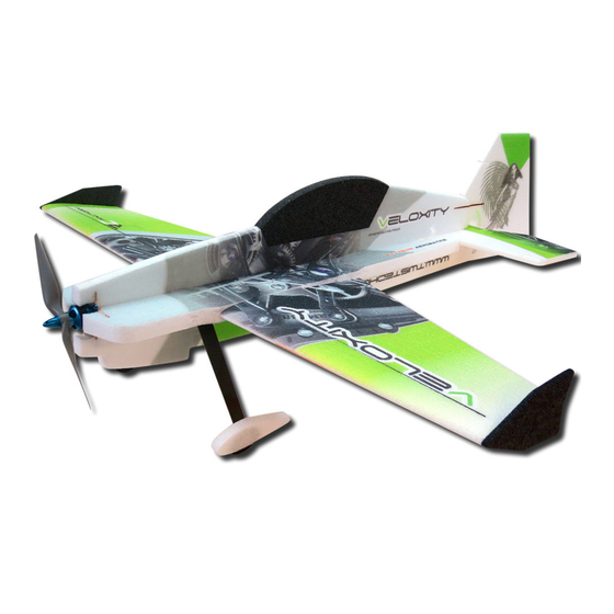
- Page 1 A CODY WOJCIK DESIGN MOTOR: 1x 100g / 1050kV Outrunner USA Distributor RADIO: 5 channel ESC: 1x 45 amp WINGSPAN: 43” Twisted Hobbys SERVOS: 4x 14g LENGTH: 44” PROP: 1x 12x6e www.twistedhobbys.com AUW: 650-750 grams BATTERY: 3s 1500mAh to 2200mAh page 1 Rev: 2015.11.30.v01a...
- Page 2 SAFETY NOTES Before assembling and flying this model, read carefully any instructions and warnings of other manufacturers for all the products you installed or used on your model, especially radio equipment and power source. Check thoroughly before every flight that the airplanes’ components are in good shape and functioning properly.
- Page 3 SHIPPING DAMAGE Twisted Hobbys checks each plane before shipping to ensure that each kit is in fine condition. We have no bearing on the condition of any component parts damaged by use, modi fication, or assembly of the model. Inspect the components of this kit upon receipt. If you find any parts damaged or missing, contact Twisted Hobbys immediately.
- Page 4 kit contents Wing Parts Fuselage Parts Double check that you have all the above pictured items. Note - Some kits might have slight deviations from the above pictured items. A DETAILED BOM IS INCLUDED AT THE END OF THIS MANUAL page 4 Rev: 2015.11.30.v01a...
- Page 5 kit contents (cont.) Tail Surfaces & Landing Gear Hardware Kit & Carbon Detail Double check that you have all the above pictured items. Note - Some kits might have slight deviations from the above pictured items. A DETAILED BOM IS INCLUDED AT THE END OF THIS MANUAL page 5 Rev: 2015.11.30.v01a...
- Page 6 TOOL AND ADHESIVES NEEDED Lighter Small Drill Bits Tape Measure and Ruler Black Sewing Thread Welders Glue Hobby Knife w/new Blade Needle Nose Pliers Wire Cutters Tools shown and listed are suggestions only. Low Temp Hot Glue Gun Depending on your building technique you may not ...
- Page 7 The above picture items will be needed to nish the model. Start the build by locating the two wings, the elevator and A power combo (Twisted Hobbys’ Combo pictured above), the rudder. Fold back as shown and weigh them down for and a battery.
- Page 8 Welders, Foam-Tac or CA can be used After the hinged parts have sat folded Start from the top side and with the as the primary method of joining the back for an hour or so, assembly can 3x1x250 spar. With the tip of the parts.
- Page 9 Install the 5x1x250 spar into the slot. Next is the two pieces that install as Fill both slits with Welders. Make sure it is ush and wipe away pictured above. Some kits have 2 pieces any extra glue. 3x1x100, some have 1 piece 3x1x200. If your kit has the 200mm long piece, cut it in half.
- Page 10 Do this for both sides. Double check The “Tack Up” method will be used to Make sure that during the “transfering” that you are working with the join the wings to the fuselage. Apply a of glue process that an even coat is on BOTTOMS of all three parts facing UP.
- Page 11 With the nozzle of the Welders’ tube, Install the spar, make sure that it is Wipe away any extra glue. Note - just squeeze some glue into the precut slot. fully seated and ush to a little below pass over once with a paper towel, the surface of the wing wiping a second or third time will mess up the printing on the foam.
- Page 12 With under side of the fuselage and the Make sure the two pieces are fully Once the previous step has dried, underside of the elevator facing up, seated to each other. If so, squareness prepare to install the fuselage glue the two pieces together. The should be really close, double check stiffeners.
- Page 13 While the previous step is drying, locate Break out the 3 landing gear base parts Take a close look at the the next three the ber glass parts tree. as pictured above. Roughen up the legs pictures to get the right orientation of of the two side pieces and one complete the parts.
- Page 14 Firewall and associated carbon stiffener This build will be done with the - TEST FIT - spars are next. Locate the motor mount Optional Upgrade Motor Mount This and the next three pictures show and four 2.5x1.5x200 carbon pictured above, the stock wood one will test tting of the motor mount, the rectangles.
- Page 15 Once you are happy with the tment Start by attaching the motor mount. Apply some Welders to the horizontal and understand how all the part are Put some glue into both the left and tabs, front and back as shown. installed, remove them all and prepare right slots as shown.
- Page 16 Install the rectangles like was done on Apply a medium coat of Welders to the Squeeze some glue into each of the four the top, and again making sure that under side of the LG Platform. holes where the tabs will insert. they engage the notches in the motor mount Apply some weights to the whole thing...
- Page 17 Avoid glue in the area where the carbon Avoid glue in the area where the With the main part of the assembly nice landing gear struts will pass. elevator and rudder servos install. and at on your work surface, press the lower horizontal into all it’s tabbed areas, don’t forget to put glue on the motor mount tab and slot as well.
- Page 18 Once the glue has tacked up, bring the Locate all the items pictured above. Enlarge the second in servo horn hole two piece togehter. Deburr the break out tabs and roughen to .060” diameter and match drill a up the bases of the horns and tail skid. .080”...
- Page 19 All the servo cut outs need to have slits Press the servo in, making sure it goes Locate the two shortest 1.8mm dia added for the servo tangs. Position the all the way ush. It may be necessary carbon rods (they may be a little servo directly over the hole and make a to make a little relief in the foam for the longer), 2 brass ferrules and 4 ball...
- Page 20 Install on of the other ball links onto Attach the control rod to the servo and Press the servo back into is pocket, and the free end of the rod. The rod may aileron control horn as shown above. with a straight edge, align the base of need to be sanded a little.
- Page 21 Repeat the entire process with the left As with the right side, make sure and Tail control rods are next, locate the aileron servo. when gluing in the aileron control horn remaining two 1.8mm dia carbon rods, that the prole of the horn matches the 2 ferrules, 4 ball links and the control prole of the hinge cut shape.
- Page 22 Attach a ball link to the free end, again Prepare to install the Elevator servo, Cut slits for the servo tabs like what sanding a little to get the link to slide control horn and control rod. The was done with the aileron servos, and on far enough so that you get 169mm elevator road is the short of the two test t to make sure it will sit ush with...
- Page 23 Locate the Rudder servo and the upper Again, cut a slit for the servo tang. For Put a little hot glue on the edges of the vertical fuselage section. this servo, only the rear tang needs a cut out. slit. Test t and remove. Test t the top fuselage section.
- Page 24 Once you are happy with the tment, Join the two pieces together, make sure Firmly press up and down the length of apply glue to all surfaces, tabs and to feed the rudder servo wire thru the the upper fuselage piece to ensure the slots.
- Page 25 With a little bit of thin CA and Kicker, Tack up Method will be used to join the Once the Welders has tacked up join join the two piece together in the tail skid assembly to it’s spot on the the two pieces as shown orientation shown.
- Page 26 Install the carbon rectangles back into Locate the rudder and its control Squeeze some Welders into the control their slots, make sure they are ush surface horn. Note that it is installed horn slot and apply a skim coat of and wipe away any extra glue.
- Page 27 Now is a good time to apply a bead of Get the tail control rods that were built Install the elevator control rod as low temp hot glue to any places where in an earlier step and the remaining shown. Note that the ball links have a the servos meet the foam.
- Page 28 Drill .112” (3mm) dia holes in the Order of assembly as pictured above, Adjust the hex nut on the inside of the landing gear as shown. Note the starting from right to left. Long screw, wheel hub so there is minimal location is not super critical, just locate washer, wheel, washer, hex nut, pant clearance and the wheel can still spin.
- Page 29 Immediately join the to pieces together. Repeat for the other side. You should Locate the two shorter self tapping Make sure that when contact is made end up with a left and right as pictured screws. Tap the screw into the LG base that you are in the correct position, the above.
- Page 30 Once the Welders has tacked up, join Repeat for the other side. Locate the motor you will be using and the two piece together as shown. its mounting hardware. For the Upgrade mount, four 3mm allen head cap screws, for the wood mount, the four longer self tapping screws Make a part on the fuselage 275mm Play with the locations of your...
- Page 31 Once you have determined the general Under side showing one way to locate With the Twisted Hobbys Power Combo, location for all the components, stick the electronics. the servos have extra long leads, so them down with some low temp hot extensions are not needed.
- Page 32 Install a fancy prop nut if you have one, charge up some batteries and head out to your favorite ying site for some fun..!! This completes the build, it’s design and construction should give you many hours of ying enjoyment. This airplane will serve you well, whether you are relatively new to 3D ying or are a seasoned veteran.
- Page 33 center of control gravity throws Extreme & 3D Ailerons: +/- 40 deg C.G. - 275mm from nose of aircraft Rudder: +/- 45 deg Elevator: +/- 50 deg Expo to suit (40% to 60%) 275 mm Beginner & Sport Ailerons: +/- 20 deg Rudder: +/- 20 deg bat.
- Page 34 Storage in a before flying. hot car could also cause damage. Be safe and enjoy, thank you again for purchasing a Twisted Hobbys’ Product! page 34 Rev: 2015.11.30.v01a...
- Page 35 notes and s/u Sheet page 35 Rev: 2015.11.30.v01a...
- Page 36 TIPS AND TRICKS A good building surface is — drop ceiling“ panel from a local hardware store on a nice flat board Use parchment paper between the areas being glued and your work surface Heavy flat objects (like books, batteries, etc.) could be used to hold everything flat When resetting your radio, start with all the ATV‘s or throw volumes at 100%.
- Page 37 Bill of Materials - Veloxity - 43” 3D Airplane Rev: 2015.11.30.v01a Bill of Materials...
Need help?
Do you have a question about the Veloxity and is the answer not in the manual?
Questions and answers