Sign In
Upload
Download
Table of Contents
Contents
Add to my manuals
Delete from my manuals
Share
URL of this page:
HTML Link:
Bookmark this page
Add
Manual will be automatically added to "My Manuals"
Print this page
×
Bookmark added
×
Added to my manuals
Manuals
Brands
Twisted Hobbys Manuals
Toy
EXTRA SLICK
Assembly manual
Twisted Hobbys EXTRA SLICK Assembly Manual
32” airframe
Hide thumbs
1
Table Of Contents
2
3
4
5
6
7
8
9
10
11
12
13
14
15
16
17
18
19
20
page
of
20
Go
/
20
Contents
Table of Contents
Bookmarks
Table of Contents
Table of Contents
Warning Information
Shipping Damage
Our Mission
Safety Notes
Important: Prior to any Assembly
Kit Contents
Optional Parts
Tools & Adhesives Needed
Assembly
Wing / Nose / Elevator
Elevator Servo - (5G)
Aileron Servo - (9G)
Fuselage Truss
Aileron Servo Horn Assembly
Building Aileron Control Rods
Aileron Control Horns
Upper Fuselage and Rudder
Rudder & Elevator Control Horns
Push Rod Guides
Elevator & Rudder Push Rods
Installing Aileron Push Rods
Motor Mount
Side Force Generators
Receiver & Esc
Setup
Control Surface Centering
Center of Gravity
Control Throws
3D Flight
Sport
Pre-Flight & Testing
Preflight Checks
Motor
Flight Controls
Batteries
Radio
Range Check
Flight Testing
Storage
Notes
Set up Data
Advertisement
Quick Links
1
Table of Contents
2
Assembly
3
Wing / Nose / Elevator
4
Center of Gravity
5
Receiver & Esc
Download this manual
32" AIRFRAME ASSEMBLY MANUAL
EXTRA SLICK
Crack yak-55
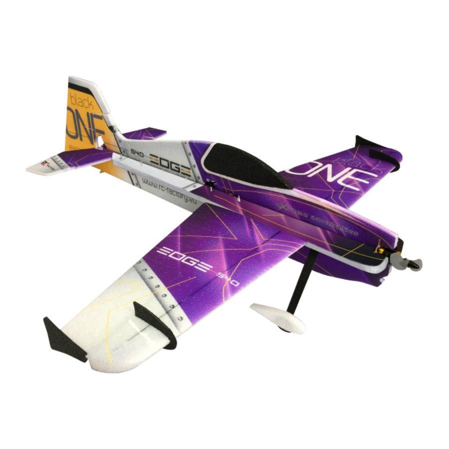
EDGE 540
Sbach 342
Specifications
Wing span – 32" / length – 31" / AUW 6-1/8oz
50w motor / 10-12 amp ESC / 4 ch radio
Twisted Hobbys
www.twistedhobbys.com
Rev: 2012.04.23a
1
Table of
Contents
Previous
Page
Next
Page
1
2
3
4
5
Advertisement
Table of Contents
Need help?
Do you have a question about the EXTRA SLICK and is the answer not in the manual?
Ask a question
Questions and answers
Related Manuals for Twisted Hobbys EXTRA SLICK
Toy Twisted Hobbys Sbach 342 Manual
1.2m (31 pages)
Toy Twisted Hobbys EDGE 540 Assembly Manual
32” airframe (20 pages)
Toy Twisted Hobbys EDGE Manual
Mini mono planes (24 pages)
Toy Twisted Hobbys Twisted Racer Mustang Manual
Twisted racer series (23 pages)
Toy Twisted Hobbys Backyard Series Manual
Yak / slick / edge / sbach (31 pages)
Toy Twisted Hobbys cCopter / 450 Assembly Manual
(40 pages)
Toy Twisted Hobbys Crack Yak-55 lite series Manual
32" r/c airplane (51 pages)
Toy Twisted Hobbys CRACK PITTS Assembly Manual
(40 pages)
Toy Twisted Hobbys YAK Manual
Mini mono planes (24 pages)
Toy Twisted Hobbys Zorro Manual
(27 pages)
Toy Twisted Hobbys Puddle Star Manual
(51 pages)
Toy Twisted Hobbys Yak and Laser User Manual
Lite series (32 pages)
Toy Twisted Hobbys Crack Turbo Beaver Manual
1450/1750kv motor (19g - 26g) 10 - 12 amp esc 5 channel radio (34 pages)
Toy Twisted Hobbys YAK Manual
Superlite indoor series, 13g - 18g motor / 30 - 50 watts, 6 - 10 amp esc, 4 channel radio, 2 x 4g - 6g servos, 1 x 8g - 11g servo, 7in - 8in prop, wingspan 32/34", length 31/35", auw 126g - 135g (37 pages)
Toy Twisted Hobbys Veloxity Manual
A cody wojcik design (38 pages)
Toy Twisted Hobbys Crack yak-55 Assembly Manual
32” airframe (20 pages)
This manual is also suitable for:
Edge 540
Sbach 342
Crack yak-55
Table of Contents
Print
Rename the bookmark
Delete bookmark?
Delete from my manuals?
Login
Sign In
OR
Sign in with Facebook
Sign in with Google
Upload manual
Upload from disk
Upload from URL


Need help?
Do you have a question about the EXTRA SLICK and is the answer not in the manual?
Questions and answers