Advertisement
Quick Links
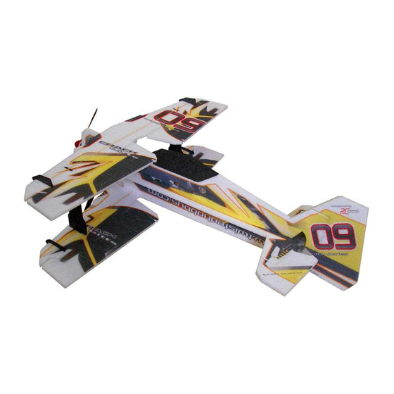
CRACK PITTS
CRACK PITTS
*SHOWN WITH OPTIONAL LANDING GEAR
MOTOR: 1x 24-26g/1450kv Outrunner
USA Distributor
RADIO: 4 channel
ESC: 1x 10-12 amp
WINGSPAN: 30"
Twisted Hobbys
SERVOS: 2x 5g - 1x 9g
LENGTH: 32"
PROP: 1x 9x4.7sf - 2s / 8x4.3sf - 3s
www.twistedhobbys.com
AUW: 180 to 200 grams
BATTERY: 2s or 3s / 450mAh
page 1
Rev: 2015.09.18.v01a
Advertisement

Related Manuals for Twisted Hobbys CRACK PITTS


Summary of Contents for Twisted Hobbys CRACK PITTS
- Page 1 CRACK PITTS CRACK PITTS *SHOWN WITH OPTIONAL LANDING GEAR MOTOR: 1x 24-26g/1450kv Outrunner USA Distributor RADIO: 4 channel ESC: 1x 10-12 amp WINGSPAN: 30” Twisted Hobbys SERVOS: 2x 5g - 1x 9g LENGTH: 32” PROP: 1x 9x4.7sf - 2s / 8x4.3sf - 3s www.twistedhobbys.com...
-
Page 2: Safety Notes
SAFETY NOTES Before assembling and flying this model, read carefully any instructions and warnings of other manufacturers for all the products you installed or used on your model, especially radio equipment and power source. Check thoroughly before every flight that the airplanes’ components are in good shape and functioning properly. - Page 3 SHIPPING DAMAGE Twisted Hobbys checks each plane before shipping to ensure that each kit is in fine condition. We have no bearing on the condition of any component parts damaged by use, modi fication, or assembly of the model. Inspect the components of this kit upon receipt. If you find any parts damaged or missing, contact Twisted Hobbys immediately.
-
Page 4: Kit Contents
kit contents Wing Parts Fuselage Parts Double check that you have all the above pictured items. Note - Some kits might have slight deviations from the above pictured items. page 4 Rev: 2015.09.18.v01a... - Page 5 kit contents (cont.) Tail Surfaces & Hardware Kit Hardware Kit Detail Double check that you have all the above pictured items. Note - Some kits might have slight deviations from the above pictured items. page 5 Rev: 2015.09.18.v01a...
- Page 6 TOOL AND ADHESIVES NEEDED Lighter Small Drill Bits Tape Measure and Ruler Black Sewing Thread Welders Glue Hobby Knife w/new Blade Needle Nose Pliers Wire Cutters Tools shown and listed are suggestions only. Low Temp Hot Glue Gun Depending on your building technique you may not ...
- Page 7 The above picture items will be needed to nish the model. Start the build by locating the two wings, the elevator and A power combo (Twisted Hobbys’ Combo pictured above), a the rudder. Fold back as shown and weigh them down for battery and a fresh tube of Welders.
- Page 8 Find the horizontal fuselage piece and Notice that the two parts are “keyed” to Once the glue has tacked up, bring the the elevator. Join them together using insure proper orientation. two pieces together, press rmly to get the Tack Up Method. a good bond.
- Page 9 Locate the vertical fuselage section, and Split the vertical fuselage section down Once all the tabs are split, you should put a fresh blade in your hobby knife. the center of the tabs. Note, the tabs have something like pictured above. have small “V”s cut in them to help locate the exact center.
- Page 10 Make sure all the tabs are fully seated While the glue is still wet, check for Locate the beveled foam trusses as as was done with the test t, wipe away squareness and tweak a little as shown above. any extra glue and weigh down so that needed.
- Page 11 Make sure the wire does not get Locate the top vertical half of the Locate the rudder servo. If using the Twisted Hobbys power combo servos, bunched up under the servo in the hole fuselage. Test t, make sure that all the no trimming will be need.
- Page 12 Once happy with the t up, remove it Starting from the front... align the nose The nose surfaces should all be ush and apply a medium bead of Welders to surfaces and work towards the tail as pictured above. In a later step, this the mating surfaces.
- Page 13 Stick the longer of the two pieces of Position so that the length of wood Apply a thin coat of Welders to both wood thru the reward slot in a diagonal matches the approx length of the slot in sides of the exposed wood stiffener. fashion, right at the intersection of the the foam.
- Page 14 Also squeeze some Welder into the slot Install the stiffener into the fuselage Wipe away any extra glue with a paper in the fuselage. from the same side that you applied the towel, and again, only one pass. glue from. Multiple passes will ruin the printed graphics.
- Page 15 Once all the tabs and scrap material is Apply a medium bead of Welders to Spread the wing, and while keeping the removed, you should be able to spread each side of the wing spar. wing slot spread, lower the spar into the wing as shown above.
- Page 16 As with the wing spars, apply a bead of Spread the strut as shown and insert Push it in all the way, making sure that Welders to both sides of the strut spar. the spar. it is ush with both sides and wipe away any extra glue.
- Page 17 If using the power combo servos you From the under side of the stock horn, Install the differential horn as shown, if should have stock horns like pictured apply some Welders to each of the the center hole is a little big, just center above, if using other servos, nd the arms.
- Page 18 Locate the two aileron control surface Install the main adjustable link part Press on the keeper clips with the horns and adjustable link pieces as into the hole as shown. Note - it is cupped side installed as pictured above, shown above.
- Page 19 Put a medium skim coat on to both Slide the gang horn into the slot. Make Position the gang horn far enough in so sides of the gang horn. sure that it is ush with both the upper that it is ush with the trailing edge of and lower surface of the wing.
- Page 20 Squeeze some Welders into the slot. Put a medium skim coat on both sides Install the horn into the wing. Note that of the horn in the area that gets buried the main part of the adjustable link into the wing. should be facing outward Wipe away any extra glue.
- Page 21 Install the rudder control horn. Again, Squeeze some Welders into the slot. Apply a medium skim coat of Welders as with the ailerons there is a precut Note that the horns to be used on the to both side of the horn base. slot on the side shown that needs to be rudder and elevator are the same, and cut all the way through.
- Page 22 Repeat the last six steps for the Locate your aileron servo, and judge Use a straight edge to modify the size of installation of the elevator horn. whether or not the cut out in the lower the cut out. wing needs to be enlarged. In the case of the power combo servos, the cutout will need to be widened slightly.
- Page 23 And the one with the blunt end installs Apply a medium coat of glue to each or Correct position is such that the edges on the upper part of the fuselage. the parts and install them into their of the wood match the edges of the appropriate positions as just foam and that the slots are aligned.
- Page 24 Once happy with the tment of the Slide the piece together. Assembly Sight down the front of the airframe upper and lower wings, the bottom should be done on a nice at surface. and make sure that every thing is nice wing will be attached rst.
- Page 25 Repeat the process on the other wing Once the glue has dried on the lower Lower the fuselage onto the upper wing strut. Put some weights on the wing as wing, the top wing can be attached. Put as shown. Note that the airframe is shown to keep things nice and at and some glue in the strut slots and other upside down for this step...
- Page 26 Once the wings and struts have dried Apply a medium skim coat to the Bring the two parts together. Take care the tail and canopy can be attached. rudder and mating surface of the stab, to get the alignment of the two pieces Tack up method will be used for both.
- Page 27 Press the two pieces together, and Locate the motor mount as shown Tack up method will be used to attach double check that the bond is good for above and with a le or some coarse the motor mount, so apply a medium the length of the joint.
- Page 28 Remove the servo horn if it was It will take a little pressure and nesse Without distrubing the center pisition installed and angle the servo into its to get the servo to pop in. Once in of the servo’s output shaft, install the pre-cut slot.
- Page 29 Starting with the aileron control rod With a heat gun, hair dryer or lighter, Apply a drop of CA to each end of the (shorter thick rods), position the snap shrink the tubing. Use caution, the shrink tubing and let it wick in. link and a piece of tubing as shown.
- Page 30 Repeat the process with the other side. Locate the tail servo arms and Attach the adjustable links as pictured adjustable link pieces. above. Notice the orientation of the links and keepers. This is important, make sure it is right, these can not be dis-assembled.
- Page 31 Starting with the elevator side, install Repeat with the rudder side. Install the elevator control rod as all the guides into the precut holes. A shown with the snap link end attached ashlight can be used to nd the holes. to the elevator surface horn, and the Make sure they are in line and put a free end thru all the guides and also...
- Page 32 Repeat the process with the other side, Snip off any extra length of the control Aileron gang control rod will is next. again making sure that the servo and rod. Leave about 1/4” past the end of Locate the longer thick rods, four snap control surface are centered.
- Page 33 Double check the length, and Repeat for the other side. The next step will require Blenderm orientation of the bosses, adjust as and Welders. Although not required, it needed and wick CA into the other end. is highly recommended. Cut 4 strips Snap the links into the gang horns.
- Page 34 Mount the motor as shown, make sure Welders or low temp hot glue can be Decide how you want to tidy up all the the leads are on the side of the airfame used to attach the ESC where desired. wires, use a little hot glue and/or zip that you want to install the ESC onto, ties.
- Page 35 Repeat the process for the other three Picture above shows how the small Finish up the program in your radio, ie, side force generators. Make sure they surface of the SFG’s is installed set the subtrims so all surfaces are are square to the wing and parallel to towards the insides of the wings.
-
Page 36: Center Of Gravity
center of control gravity throws Extreme & 3D Ailerons: +/- 40 deg C.G. - 185mm from nose of aircraft Rudder: +/- 45 deg Elevator: +/- 45 deg Expo to suit (40% to 60%) 185 mm Beginner & Sport Ailerons: +/- 20 deg Rudder: +/- 20 deg Elevator: +/- 20 deg Expo to suit (15% to 30%) -
Page 37: Pre-Flight & Testing
Storage in a before flying. hot car could also cause damage. Be safe and enjoy, thank you again for purchasing a Twisted Hobbys’ Product! page 37 Rev: 2015.09.18.v01a... - Page 38 notes and s/u Sheet page 38 Rev: 2015.09.18.v01a...
-
Page 39: Tips And Tricks
TIPS AND TRICKS A good building surface is — drop ceiling“ panel from a local hardware store on a nice flat board Use parchment paper between the areas being glued and your work surface Heavy flat objects (like books, batteries, etc.) could be used to hold everything flat When resetting your radio, start with all the ATV‘s or throw volumes at 100%. -
Page 40: Optional Landing Gear
optional landing gear With .076” drill, enlarge wheel axle, carbon ber LG and wheel pant brace. Install screw through wheel and spin nut over other end, do not tighten nut fully so wheel can spin, secure nut with CA. Then install wheel spat as shown and a fuse support.
Need help?
Do you have a question about the CRACK PITTS and is the answer not in the manual?
Questions and answers