Table of Contents
Advertisement
Quick Links
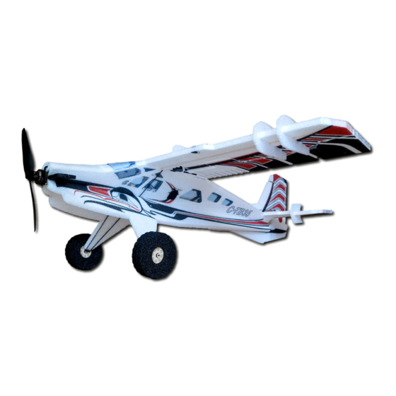
Crack Turbo Beaver
Crack Turbo Beaver
Crack Turbo Beaver
Crack Turbo Beaver
1450/1750kV motor (19g - 26g)
10 - 12 amp ESC
5 channel radio
4x 5g to 7g servos
2s/9x4.7 or 3s/8x4.3 prop
Rev: 2013.09.15.v004a
Instructions included for the Optional Float Kit
USA Distributor
Twisted Hobbys
www.twistedhobbys.com
Wingspan = 35"
Length = 30"
AUW= 7 - 8oz
1
Advertisement
Table of Contents

Related Manuals for Twisted Hobbys Crack Turbo Beaver


Summary of Contents for Twisted Hobbys Crack Turbo Beaver
- Page 1 Crack Turbo Beaver Crack Turbo Beaver Crack Turbo Beaver Crack Turbo Beaver Instructions included for the Optional Float Kit USA Distributor Wingspan = 35" 1450/1750kV motor (19g - 26g) Twisted Hobbys 10 - 12 amp ESC Length = 30" 5 channel radio www.twistedhobbys.com...
-
Page 2: Table Of Contents
TABLE OF CONTENTS TABLE OF CONTENTS TABLE OF CONTENTS TABLE OF CONTENTS Page WARNING INFORMATION ............................... 3 SHIPPING DAMAGE..................................3 OUR MISSION....................................3 SAFETY NOTES.................................... 4 IMPORTANT: PRIOR TO ANY ASSEMBLY........................4 KIT CONTENTS.................................... 5 OPTIONAL PARTS..................................6 TOOLS & ADHESIVES NEEDED .............................. 7 THE BUILD.................................... -
Page 3: Warning Information
SHIPPING DAMAGE Twisted Hobbys checks each plane before shipping to ensure that each kit is in fine condition. We have no bearing on the condition of any component parts damaged by use, modification, or assembly of the model. Inspect the components of this kit upon receipt. If you find any parts damaged or missing, contact Twisted Hobbys immediately. -
Page 4: Safety Notes
SAFETY NOTES SAFETY NOTES SAFETY NOTES SAFETY NOTES Before assembling and flying this model, read carefully any instructions and warnings of other manufacturers for all the products you installed or used on your model, especially radio equipment and power source. Check thoroughly before every flight that the airplanes’... -
Page 5: Kit Contents
kit contents kit contents kit contents kit contents PARTS LIST AIRFRAME COMPONENTS DETAIL - HARDWARE PACK 1x Wing (2pcs) 1x Antennalizer/Stack Kit 2x 1mm Dia x 49mm Carbon Rod (Aileron Control Rod) 1x Left Fuse 6x Black Wheel Pieces 2x 2mm Dia x 40mm Carbon Rod (Wheel Axles) 1x Right Fuse 1x Elev. -
Page 6: Optional Parts
OPTIONAL PARTS OPTIONAL PARTS OPTIONAL PARTS OPTIONAL PARTS Perfect choice for building and repairing your Twisted Hobbys EPP planes! This is the only adhesive you will ever need. Crack Power Combo Welder virtually bonds anything Blenderm tape is one of the... -
Page 7: Tools & Adhesives Needed
Tools Tools Tools Tools & & & & Adhesives Needed Adhesives Needed Adhesives Needed Adhesives Needed • Lighter • Small drill bits • Tape Measure and Ruler • Black Sewing Thread • Welders Glue • Hobby Knife w/new Blade • Needle Nose Pliers •... -
Page 8: The Build
THE BUILD THE BUILD THE BUILD THE BUILD CONSTRUCTION METHODS: Building surface should be at least 2ft x 4ft and flat. Weights or some small heavy objects will be handy for holding things in place during the time glue is setting. Welders glue is the primary adhesive used for this build. - Page 9 Make a new program in your Radio. Zero all Identify the porper pins for the; Throttle, Compare your Reciever to the included the Trims and Subtrims. For starters all the Aileron, Elevator and Rudder Channels. diagram from the side as shown above. ATVs can be set to 100%.
- Page 10 …. reconnect the battery to the ESC and listen for two quick short beeps, immediately following the beeps, move the Throttle stick to low position. Next you should hear a series of tones to indicate that programing is complete. Re-bind the system and double check correct operation of all components.
- Page 11 Dip the end of the control rod approx Attach one of the snap links to the end Remove all the little pieces from the cut 1/2" into the Welder's nozzle to achieve of the glue coated rod. Note that the outs in the wing halves.
- Page 12 Remove the webbing from the spar slot. Spread the slot apart and test fit the Rounding the ends of the spar will help spar. it slide into the slot a little easier. Coat both sides of the spar with a Install the spar into the wing slot, make While the Wing is drying, install the medium bead of Welders...
- Page 13 One fueslage half gets split as shown. It Locate the four landing gear strut Test fit. Force glue into the provided is the one that has the little tick marks spars. slot and lay carbon spars in as shown. at the center of each tab. Note that on one side the spar sticks out.
- Page 14 While the glue is still wet on the EPP Install one of the axles thru the center Repeat with the other wheel and set pieces, install the wood hubs on the of the hubs to insure the concentricity aside under some weight to dry. front and back, again wet and with a of all the parts.
- Page 15 Fit the right lower fuselage part ..and behind the spar of the full Fully engage the tabs and slots, taking together with the full fuselage side. section. The foam tab and slots should note of how it all goes together. Note that the spar from the right side line up better with the spars situated in sticks thru the hole..
- Page 16 Apply glue to all the mating surfaces of Fit together as per the test fit With the nozzle of the Welder's tube, the lower fuselage section as well as all remembering to keep the free end of the force a small bead of glue into the slot the mating tabs and surfaces.
- Page 17 Loosely fit the axle and one of the hex Top View of axle alignment. While in this position apply some nut shaped wood piece as shown above. Welders and allow it to set up for a Note that some sticks out to the inside couple hours.
- Page 18 All the pieces seperated and ready for Check fit of the elevator spar, then with Install the spar, wipe away any extra assemlby in later steps the Welder's nozzle, force a small bead glue and set aside to dry. of glue into the slot for the elevator spar.
- Page 19 Once the glue has tacked up, stick it to The small cowling part is next. Seperate it from the larger part, and the mating surface on the nose. glue to the nose, directly behind the motor mount. This can be installed wet. Tail Control Horns.
- Page 20 Repeat the process with the Rudder Make sure that the contour of the horn The two remaining horns are for the Horn. matches up with the inside of the hinge ailerons. They will be installed from the for proper horn alignment. underside of the wing.
- Page 21 Glue the two piece together, making Set them aside to dry. Once dry the tail assembly can be sure they are square to each other. jointed to the fuselage. Do not put glue on the bottom most part of the rudder, this will be glued with the fin.
- Page 22 Make sure that the rudder and fin are Install the tail servos. Body of the servo Intall the motor. straight to each other and allow to dry. should be flush with the outside of the fuselage and servo arms centered and attached.
- Page 23 Install the adjustable links, install the If adjustments need to be made after Locate your wing servos and the short control rod. Snap the other ended into the build is complete, there is still control rods that were made at the the surface horn, center servo and access to the adjustable link from the beginning of the build.
- Page 24 Coat all the mating surfaces with glue Top View..double check that the Install the wheels onto the axles. Holes and install as shown. Use stick pins or elevator SFG's are parallel to the may need to be enlarged slightly. tape if necessary to hold in position fuselage and perpendicular to the while the glue sets up.
- Page 25 Locate the Antalizer and glue it to the Prepare to install the wing by hooking Apply a nice thick bead of Welders to rear center fo the wing assembly. Make up the aileron servo wires to the RX. the saddle area of the fuselage. sure it is square to the wing.
- Page 26 Locate the rear-ward piece as shown, Split the out-board SFG's as shown. Install into the provided slots. Make repeat for the other side. sure the are parallel to the fuselage and square to the wing. With a left over piece of carbon from the Poke a hole in the rear of the lower fin, If you have already programmed your tail push rods, make a tail skid...
- Page 27 Cowling installed Windscreen can also be installed now. Install the turbo exhaust stacks as For 3D and Extreme flying, leave this shown. part off. For Sport and Trainer flying it can be installed. Final Notes: The Turbo Beaver is a very durable plane will...
- Page 28 "Flaps & Spoilers" Section on the next page. Sample shown is from a DX8, other Radios will be similar. Another really good source of information for this and other Twisted Hobbys' planes is RCGroups.
-
Page 29: Center Of Gravity
Center of Center of Center of Center of Control Throws Control Throws Control Throws Control Throws Gravity Gravity Gravity Gravity Extreme & 3D CG - 2.187" from leading Edge of Wing Ailerons - approx +/- 40 deg Rudder - approx +/- 40 deg Elevator - approx +/- 40 deg Expo to suit Beginner &... -
Page 30: Pre-Flight & Testing
If there is insufficient Storage in a hot car could also cause damage. range or significant reduction with the motor running, resolve and re-test before flying. Be safe and enjoy, thank you again for purchasing a Twisted Hobbys’ Product! Rev: 2013.09.15.v004a... -
Page 31: Notes & S/U Sheet
NOTES NOTES & s/u Sheet NOTES NOTES & s/u Sheet & s/u Sheet & s/u Sheet Rev: 2013.09.15.v004a... -
Page 32: Tips And Tricks
TIPS AND T TIPS AND T TIPS AND T TIPS AND TRICKS RICKS RICKS RICKS A good building surface is “drop ceiling” panel from a local hardware store on a nice flat board • Use parchment paper between the areas being glued and your work surface •... - Page 33 …Enjoy! Rev: 2013.09.15.v004a...
-
Page 34: Float Assembly Instructions
Appendix Appendix Appendix Appendix A A A A Float Assembly Instructions Rev: 2013.09.15.v004a...
Need help?
Do you have a question about the Crack Turbo Beaver and is the answer not in the manual?
Questions and answers