Advertisement
Quick Links
P
U
D
D
L
E
S
T
A
R
P
U
D
D
L
E
S
T
A
R
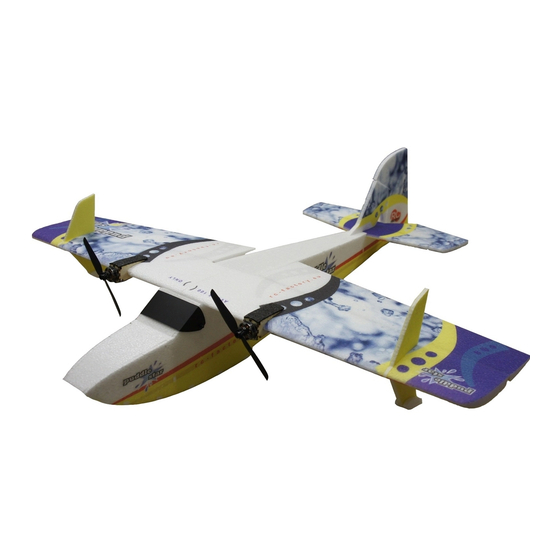
MOTOR: 2x 19-26g/1450-1750 Outrunner
USA Distributor
RADIO: min. 4 channel
ESC: 2x 10-12 amp
WINGSPAN: 39"
Twisted Hobbys
SERVOS: 4x 5-7g
LENGTH: 39"
PROP: 2x 7x3.5dd or 7x6sf
www.twistedhobbys.com
AUW: 390 to 420 grams
BATTERY: 3s / 650-850mAh
page 1
Rev: 2015.08.16.v01a
Advertisement

Related Manuals for Twisted Hobbys Puddle Star


Summary of Contents for Twisted Hobbys Puddle Star
- Page 1 MOTOR: 2x 19-26g/1450-1750 Outrunner USA Distributor RADIO: min. 4 channel ESC: 2x 10-12 amp WINGSPAN: 39” Twisted Hobbys SERVOS: 4x 5-7g LENGTH: 39” PROP: 2x 7x3.5dd or 7x6sf www.twistedhobbys.com AUW: 390 to 420 grams BATTERY: 3s / 650-850mAh page 1...
-
Page 2: Safety Notes
SAFETY NOTES Before assembling and flying this model, read carefully any instructions and warnings of other manufacturers for all the products you installed or used on your model, especially radio equipment and power source. Check thoroughly before every flight that the airplanes’ components are in good shape and functioning properly. - Page 3 SHIPPING DAMAGE Twisted Hobbys checks each plane before shipping to ensure that each kit is in fine condition. We have no bearing on the condition of any component parts damaged by use, modi fication, or assembly of the model. Inspect the components of this kit upon receipt. If you find any parts damaged or missing, contact Twisted Hobbys immediately.
-
Page 4: Kit Contents
kit contents Wings, SFG’s and Tail Surfaces Fuselage Parts Double check that you have all the Double check that you have all the above pictured items. Note - Some above pictured items. Note - Some kits might have slight deviations from kits might have slight deviations from the above pictured items. - Page 5 kit contents (cont.) Plywood and Hardware Kits Hardware Kit Detail Double check that you have all the Double check that you have all the above pictured items. The Hardware above pictured items. Note - Some kit items are detailed to the right. kits might have slight deviations from Note - Some kits might have slight the above pictured items.
- Page 6 TOOL AND ADHESIVES NEEDED Lighter Small Drill Bits Tape Measure and Ruler Black Sewing Thread Welders Glue Hobby Knife w/new Blade Needle Nose Pliers Wire Cutters Tools shown and listed are suggestions only. Low Temp Hot Glue Gun Depending on your building technique you may not ...
- Page 7 The above picture items will be needed to nish the model. Start the build by locating the two wing halves, the elevator A power combo (Twisted Hobbys’ Combo pictured above), a and the rudder. Fold back as shown and weigh them down 3s/650-850mAh battery and a fresh tube of Welders.
- Page 8 Locate the wood kit and mount a fresh Cut out the Fuselage Doublers, the Press a magnet into the Wood Holder blade into you hobby knife. Wing Mount Cross Members and the (the one with the larger hole). Make little round Magnet Holders. Also locate ush with one side.
- Page 9 Coat the inside of the magnet hole in Install as shown, again remembering Press into the hole... should be ush to the fuselage with a little Welders. that the smaller hole is facing out. both the inside and outside of the foam fuselage piece.
- Page 10 LAMINATING BUILD TIPS There are many different thickness and brands of laminate material out there. You should use a laminate that has a low heat activated glue. As an extra step to insure a robust bond of the laminate to the foam, 3M 77 Contact Spray glue can be used to “dust”...
- Page 11 Waterbug Build Only - Once you are Waterbug Build Only - Once everything Waterbug Build Only - Repeat the happy with the lm application, Trim is trimmed up, seal all the edges. process with the outside surface of the around the perimeter of the elevator, two fuselage pieces.
- Page 12 Spread the glue out evenly so that it Attach to the inside of the fueslage. The foam doubler will curl up a little as coats the whole surface. Use an old NOTE - it is VERY important to line up the Welders dries, so secure everything business card or something as a all the notches and edges of the two...
- Page 13 Repeat for the other side and put all the Locate the parts shown above. Attach them and cut off the extra weights back until everything has had length of the screws so they are ush time to dry. Locate all the internal bulkheads and Start with the pieces shown above.
- Page 14 Note the orientation of the parts, Tabs This piece installs as shown. again Once you get it all together and you are are keyed, but in some cases there is notice the little hole. happy with the t up, re-assemble with more than one way to put these Welders.
- Page 15 DRY FIT - Notice the orientations of the DRY FIT - the main rear bulkhead. DRY FIT - the tail section bulkhead. rear wing mount cross member and bulkheads shown. DRY FIT - looking down from the top, DRY FIT - Close up of the front wing DRY FIT - the other side of the fuselage.
- Page 16 DRY FIT - close up of the rear wing DRY FIT - Close up of the tail section. DRY FIT - Locate the belly parts shown. mount cross member installed. DRY FIT - the bottom front section. DRY FIT - the upper nose cover. DRY FIT - the belly pieces into their location.
- Page 17 DRY FIT - Notice that one side is relief DRY FIT - Look carefully at the nose, DRY FIT - When you have removed cut so that the part will bend easily and you will see that there is a little enough material from the edge of the t the designated area.
- Page 18 Close up of how the servo should be Start the re-assembly of the fuselage by Then install the bottom and use seated into the cut out in the wood. putting Welders on all the mating masking tape to hold all the parts in Once you are happy with the t up, surfaces between the bulkhead parts place.
- Page 19 If you have not already done so, now is Create a new model on your radio and WING TYPE a good time to test your electronics. bind per your mfg’s procedures. The For this model, pick the “Dual Ail” wing Above is a picture of a typical layout for next couple steps will show how to mix type and “Normal”...
- Page 20 Glue the arm extenders onto the back Make sure the servos are electronically If a couple hours have passed already, side of the single sided servo arms. CA centered and mount the arms with the fuselage should have dried enough or Welders.
- Page 21 Locate the four small plastic links as TEMPORARILY mount the links onto Locate the 1mm round push rods and shown and the small (1mm ID) the elevator and rudder servo horn’s the white push rod guide tubes as threaded ends. Thread the links on so outer most hole.
- Page 22 Feed the push rod guides thru the Dry Fit and when happy with how Use some small tabs of tape or stick slots, making sure that they do not get everything lines up, remove and add pins to hold things in place while the crossed in the process.
- Page 23 With the nozzle of the Welders tube, Install the horn, wipe away any extra Check on the hinge cut out side that force some glue into the slit, and also glue, bend part of the elevator up and the prole of the horn matches the apply a thin coat to the mounting area use the crease in the foam as a prole of the hinge cut.
- Page 24 Double check that the prole of the Waterbug Build Only - hold the elevator Waterbug Build Only - remove the horn is matched up with the prole of up to the fuselage and take note of laminate material in the area noted. the hinge cut.
- Page 25 When you get to about an inch of ... and add some glue to the areas that Fully engage the two pieces, wipe away clearance, stop there... will contact each other any extra glue. Set aside and let the glue set up. While the tail is curing...
- Page 26 Remove the center wing rib from the kit Test t the rib into the fuselage as The rear tongue and front tab should as shown above. shown. both engage without any force. Use the Tack Up Method..coat one Once the glue has tacked up, attach the Note how the open area of the wing rib lines up with the center of the black side of the rib and the mating surface of...
- Page 27 Snip away the little connector spacers. The Wing Mounting Screw should pass Using the tack up method again, coat through freely. the mating surfaces with a medium skim coat of Welders and allow to tack Once the tail section has dried, it can Make sure the push rods are on the Once the Welders has tacked up, bring the two pieces together.
- Page 28 Line up the front rudder tab with the Fully engage the tabs of the rudder into Once satised with the tment, remove slot in the upper fuselage deck. the fuselage. Check to make sure all and add Welders to all the mating the surfaces are meeting up ush.
- Page 29 The object is to cut a slot in the wing to Using the notch as a reference, line up Adjust back and forth until you have receive the carbon round. Notice that your straight edge so that it passes the exact same measurement on both there is a notch in the wing rib that is thru the notch and is parallel to the sides of the wing.
- Page 30 Wipe away any extra glue with a paper Repeat for the bottom side... cut a slit ..squeeze in some Welders..towel. Just go over it once. Repeated 2mm deep that is parallel to the wing..passes will mess up the printed graphics.
- Page 31 Locate the wood parts kit and remove Dry Fit - Notice that there is a notch on Dry Fit - Do both sided, making sure the remaining parts, which should the rewall part, this is the BOTTOM, that the wing pieces are fully engaged make up the motor mounts.
- Page 32 Secure all the parts to one another and Using the screws provided with the Repeat with the other motor. to the wing with thin CA and Kicker. motor, mount the motors to the rewall. If using the TH Power Combo motors, drill the holes out to 1.5mm, this will keep the wood from splitting.
- Page 33 If choosing to mount the ESC’s in the Water proong the ESC’s and Rx is Read the instructions on the Plastic Dip cabin area, some short extensions will next. Either Plastic Dip or Liquid Can. Grab one of the ESC’s by the wires need to be made up, this will be done Electrical Tape will work.
- Page 34 Once the Liquid Electrical Tape has If there is anything exposed, just add a Set everything aside and let dry for the dried, inspect to verify that all the little more of the Liquid Electrical Tape recommended time.While these are components are sealed and covered.
- Page 35 Cut the extensions to length and attach Make sure the wires are buried deep Repeat the process for the other side. bullets. Protect with heat shrink, clear enough to allow the motor pod cover to heat shrink was used in this build, but set ush.
- Page 36 ... and with an old business card, Once the glue has tacked up, cut a Lay the tape down and press rm to get spread the Welders out to a skim coat piece of clear HD packing tape to t the it all stuck down good.
- Page 37 Repeat the process for the top side. Completed. Locate the aileron control surface horns. Test t the horn, make sure the slit is Remove the horn and squeeze in some 20mm in from the edge of the aileron, cut a slit to accept the horn. cut so that the hole in the horn is Welders.
- Page 38 Wipe away any extra glue and double Repeat for the other side. Locate the brass ferrules, clevises and check alignment with the hinge line. carbon push rods. The other ferrule, attaches to the Center the rudder. With thin CA, attach the ferrule to one end of each rod.
- Page 39 From the end of the ferrule, measure ... and cut away the white push rod Clean out the end of the tube with the 30mm... guide tube. tip of a hobby knife. Repeat this and the pervious four steps for the elevator. Repeat for the elevator, and snap them There should be a little extra carbon Take the longer of the two rods that you...
- Page 40 Slide on one of the two push rod guide Just let the guide hang freely for now. Center the rudder and cut the carbon supports. rod with a pair of sharp side cutters. For reference, once the rod is inside the ferrule, it will extend approx to the area where the threads start.
- Page 41 Hold the elevator control surface level, Deburr the end of the carbon rod, and Again... while holding the elevator level, and cut the rod so that it is just shy of slide onto the ferrule. apply thin CA and Kicker as was done the threaded area of the ferrule.
- Page 42 Insert the rod into the ferrule and glue With the wing attached to the fuselage, Locate the two thin carbon strips from with thin CA and Kicker. Repeat with attach the control rod as shown, use the hardware bag and the SFG,s/Wing the CLEVIS ONLY on the other end of the middle hole on the extended servo Skids.
- Page 43 Tips are next. It should be noted that Attach as shown. Apply a couple small Next the Wingtip skids will be these parts are Depron and FOAM beads of CA to the white part, spray the attached... start by applying a bead of SAFE glue MUST be used when tip of the skid with Kicker and join the Welders to the slot in the wing and...
- Page 44 Repeat the process for the other side. Locate all the windscreen parts as Hold the windscreen up to the fuselage pictured above. as shown. NOTE THE ORIENTATION. With a Sharpe, mark where the edges of the fuselage are. With a straight edge, line up on the Attach the allen head screw and plastic Make a mark on the other end as well.
- Page 45 Install the windscreen. The heads of the If you have not already attached all the Double check that the motors are screws should engage into the little wires inside the cabin, you can do that rotating in the proper direction. round wood washers, and held in place now.
- Page 46 Grasshopper Build - Cover the sides Grasshopper AND Waterbug Build - Hook up all the electronics inside the with clear packing tape and trim ush. with Heavy Duty or clear Gorilla tape, Cabin again, and re-check that cover the bottom surfaces. Trim ush everything is functioning normally.
- Page 47 One of the best online resources for this model is the RC Groups thread that was started specically for the Puddle Star. RC Groups Puddle Star Build and Discussion Thread http://www.rcgroups.com/forums/showthread.php?t=2279304 This model is sure to impress your ying buddies, a 3D Double check everything one last time.
-
Page 48: Control Throws
center of control gravity throws Extreme & 3D Ailerons: +/- 40 deg C.G. - 11.61in from nose of aircraft Rudder: +/- 45 deg Elevator: +/- 45 deg Expo to suit Beginner & Sport 11.61 inches Ailerons: +/- 20 deg Rudder: +/- 25 deg Elevator: +/- 25 deg Expo to suit In order to achieve the control throws as... - Page 49 Storing in other fashions that put stress on before flying. the airframe could cause the airframe to distort. Storage in a hot car could also cause damage. Be safe and enjoy, thank you again for purchasing a Twisted Hobbys’ Product! page 49 Rev: 2015.08.16.v01a...
- Page 50 notes and s/u Sheet page 50 Rev: 2015.08.16.v01a...
- Page 51 TIPS AND TRICKS A good building surface is — drop ceiling“ panel from a local hardware store on a nice flat board Use parchment paper between the areas being glued and your work surface Heavy flat objects (like books, batteries, etc.) could be used to hold everything flat When resetting your radio, start with all the ATV‘s or throw volumes at 100%.
Need help?
Do you have a question about the Puddle Star and is the answer not in the manual?
Questions and answers
Menu how to install Puddle Star to FrSky x 14