Table of Contents
Advertisement
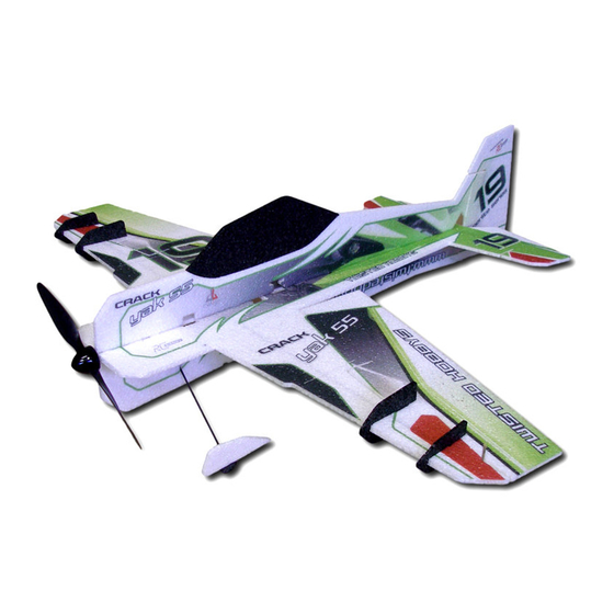
32" Crack Yak-55
Specifications
Wing span – 32" / Length – 31"
AUW 160-175g (with Landing Gear)
50 - 70w outrunner motor (19g – 24g)
6 - 12 amp ESC / 2s 360 – 450mAh battery
4 ch radio / 2x 4g servos / 1x 9g servo
8x4.3 prop
USA Distributor
Twisted Hobbys
www.twistedhobbys.com
Rev: 2012.11.04.v004a
RC Factory
RC Factory
RC Factory
RC Factory
By
1
Advertisement
Table of Contents

Related Manuals for Twisted Hobbys Crack Yak-55 lite series


Summary of Contents for Twisted Hobbys Crack Yak-55 lite series
- Page 1 AUW 160-175g (with Landing Gear) 50 - 70w outrunner motor (19g – 24g) 6 - 12 amp ESC / 2s 360 – 450mAh battery 4 ch radio / 2x 4g servos / 1x 9g servo 8x4.3 prop USA Distributor Twisted Hobbys www.twistedhobbys.com Rev: 2012.11.04.v004a...
-
Page 2: Table Of Contents
TABLE OF CONTENTS Page WARNING INFORMATION..............................3 SHIPPING DAMAGE................................3 OUR MISSION ..................................3 SAFETY NOTES ..................................4 IMPORTANT: PRIOR TO ANY ASSEMBLY ......................4 KIT CONTENTS ..................................5 OPTIONAL PARTS ..................................6 TOOLS & ADHESIVES NEEDED............................7 THE BUILD ....................................8 CENTER OF GRAVITY ................................48 CONTROL THROWS ................................48 3D Flight ..................................48 Sport ....................................48 PRE-FLIGHT &... -
Page 3: Warning Information
These instructions are suggestions only on how to assemble this model. There are other ways and methods to do so. Twisted Hobbys has no control over the final assembly, the materials and accessories used when assembling this kit, or the manner in which the assembled model, installed radio gear and electronic parts are used and maintained. -
Page 4: Safety Notes
SAFETY NOTES SAFETY NOTES SAFETY NOTES SAFETY NOTES Before assembling and flying this model, read carefully any instructions and warnings of other manufacturers for all the products you installed or used on your model, especially radio equipment and power source. Check thoroughly before ever flight that the airplanes’... -
Page 5: Kit Contents
kit contents kit contents kit contents kit contents R C F a c t o r y 3 2 ” C r a c k Y a k - 5 5 , l i t e standard parts list: hardware packet: 2x –... -
Page 6: Optional Parts
4x - Landing Gear Washers Perfect choice for building and repairing your 4x - Wing Spar Braces Twisted Hobbys EPP planes! This is the only adhesive you will ever need. Welder virtually bonds anything to anything! Clear, heavy-duty, flexible Note: many of these “optional parts” shown or and water-proof when dry. -
Page 7: Tools & Adhesives Needed
Tools & & & & Adhesives Needed Tools Adhesives Needed Tools Tools Adhesives Needed Adhesives Needed • Tape Measure and Tape Measure and Ruler Ruler Tape Measure and Tape Measure and Ruler Ruler • Lighter Lighter Lighter Lighter • Small drill bits Small drill bits Small drill bits Small drill bits... -
Page 8: The Build
THE BUILD THE BUILD THE BUILD THE BUILD CONSTRUCTION METHODS: Building surface should be at least 2ft x 4ft and flat. Weights or some small heavy objects will be handy for holding things in place during the time glue is setting. Two types of glue are used for the build, Welders glue is use for most areas and CA for the horns and guides. - Page 9 Remove the little tabs of foam that are in the SFG slots with a sharp knife Glue the wings to the fuselage with Welders. Notice how the tabs on each wing prevent you from putting the wings on upside down. NOTE: USE GLUE SPARINGLY AND WIPE OFF OR REMOVE ANY EXCESS.
- Page 10 Welders will work it’s way through the top of the wing. Use some clear packing tape on the bench to keep it from sticking. Wax paper or Parchment paper could also be used. Install the rods thru the wood ribs as shown.
- Page 11 Lay down a bead of Welders into the rib and spar areas. Lower the assembly into the provided slots allowing any extra glue to squish out. The short spar should be buried in the middle section and the long spar should be flush with the bottom of the wing.
- Page 12 Weigh it down flat on a flat surface and let it dry completely. Pay special attention to ensure that the wing is flat and the spar is straight and true. Get ready to install the elevator. Put Welders on the end of the Fuse and let it tack up.
- Page 13 After tacking minutes assemble the elevator to the fuselage piece. Notice there is a tab on the stab and fuse that will keep you from putting them on backwards. Assembled elevator to fuselage. Now install the lower part of the fuselage.
- Page 14 Put Welders in the tab slots and flat spots between the tab slots on the horizontal fuse piece. Be cautious not to put Welders in the servo hole areas. Put the lower fuse onto the horizontal fuse piece while the glue is wet. Make sure it is 90 degrees to the horizontal piece and clean up all the excess glue.
- Page 15 Put Welders on the control horn. Install the control horns while the glue is wet and let dry. You may have to cut out the EPP fuzz in the slot in the wing to get the horn to sit flush. Trial fit before gluing.
- Page 16 Install the upper part of the fuse. Put Welders on the tab slots and flat part of the fuse. Put Welders on the flat parts and tabs of the upper fuse piece, insert wet and let dry. Take care to make sure the upper fuse is in line with the lower fuse and 90 degrees to the horizontal fuse piece.
- Page 17 Clean up any excess glue. While the upper fuse is drying put Welders on the canopy area and let it tack up. Put Welders on the canopy itself and let it tack up. Rev: 2012.11.04.v004a...
- Page 18 After the glue has tacked up, attach the canopy to the fuse. Make sure it is going in the right direction! Put Welders on the Fuse find side and let it tack up. Put Welders on the fuse fin side and let tack up.
- Page 19 While the glue tacks up install the control horn in the rudder the same way we did with the ailerons. Rudder Horn After the Welders has tacked up glue the rudder to the fuse. Start at the top so you can manage the fin to rudder gap and work your way down.
- Page 20 Now you can install the elevator control horn. Elevator Horn Now install the side trusses. Cut one of the tips off the trusses so that you can run the servo wires from the tail servos out of the and tuck the wires back into that space after it is all finished to clean up the radio install.
- Page 21 Again, as the glue dries on the trusses keep tweaking and checking to make sure everything is totally straight. These are all the parts to build the LG assembly. 1X - Wood Landing Gear Parts 2X - Carbon Rounds for Axles 2X - Carbon Rectangles for Struts 2X –...
- Page 22 Second, you will glue the little ply angle piece (Axle Support) to the end of one of the gear legs with thin CA. Axle Support The angle and flat spot created by the ply piece and the carbon gear leg makes a nice joint to glue in the carbon axle with thin CA.
- Page 23 Make sure all the pieces are thin CA’d securely. Then wrap the whole joint with thread. After it is wrapped with the thread, hit it with thin CA and kicker to finish of the gear leg. Rev: 2012.11.04.v004a...
- Page 24 This piece is very strong and light! Next, you will put on the ply wheel pant mount/wheel keeper. It just slides over the axle and glues in place with medium or if you are careful thin CA. If your kit had 4 of the round washers, make sure to put the second one on before gluing on the Pant Support.
- Page 25 Fill the slot with welders. Note – some kits have slots located closer to the nose as shown below. There are also two slots in the horz. fuse piece for the gear legs. Fill them with Welders too. NOTE NOTE – – – – If your kit has the forward located NOTE NOTE If your kit has the forward located...
- Page 26 Once the gear leg comes through the fuse, install the oval ply piece over the end of the leg and insert the leg into the slot in the horz. fuse piece. Some kits may not have this part, if this is the case with yours, simply glue right into the foam.
- Page 27 Make sure you have enough Welders in slots and covering the ply pieces. Omit this step if your kit did not come with these oval parts. On the center crossing of the gear legs you will want to take some thread and wrap it around the entire X assembly and ply plate.
- Page 28 Let the glue dry on the gear assembly without weight on the gear. Make sure everything place stays straight as it dries. Put Welders on the wheel pant mounts and let it tack up. Put Welders on the wheel pants and let them tack up.
- Page 29 While the glue tacks up on the wheel pants, lets build the pushrods. Scuff up one end of each carbon rod, and the long part of the z-bend. Wipe clean. Install the shrink tube and z-bend as shown. (Scuffed end) Then, let a drop of CA run down the rod and underneath the shrink tubing.
- Page 30 Heat the heat shrink to squeeze out excess CA. Hit it with kicker and set aside. Here are four completed pushrods ready to install. Rev: 2012.11.04.v004a...
- Page 31 Take all the pushrod guides out of the ply sheet and put six on each of the longer two pushrods. Push Rod Guide Install the long pushrods in the tail starting by inserting the Z bend in the tail control horns. Then, using med CA find the first small lasered hole for the pushrod guides and fill it with glue.
- Page 32 Install the first guide, push it into place not all the way down to the foam and kick it while holding it in place. Continue with each subsequent pushrod guide. Be very careful not to get any drops of CA onto the pushrods. Rev: 2012.11.04.v004a...
- Page 33 Now assemble the elevator push rod guide assembly just as you did with the rudder. Time to install the Servos Take the longest servo arm in the hardware package for the servo and scuff up the top side of it. Note Note –...
- Page 34 Put a dab of thin CA on the servo arm. Now find and remove the two small ply oval shaped ply servo arm extenders that come in the hardware kit. Note you must attach to the top side of the servo arm, also make sure you do not add too much glue since the Adjustable End Link will need to spin freely...
- Page 35 After it is dry, wrap it with thread, and CA, hit with kicker Completed Assembly. To install the Adjustable links, insert the block thru the horn hole and than with the concaved side facing in, press the keeper washer onto the shaft. Remember that the Link must spin freely, so do not press the keeper on too tigh.
- Page 36 Install the servos. I like to install the servos after the airframe is built. Of course you could install them as you build the plane. With the thin EPP it is very easy to install them after constructed and then you can use a very little dab of welders Fish the wires through the fuse and out of the front of the cut off truss.
- Page 37 To insert the rod into the keeper, deflect the elevator all the way down and cut off the rod right at the servo keeper. Check to make sure that the Keeper rotates freely, if not, binding will occur in the control system Install the rod into the keeper and center the surface.
- Page 38 Installed keeper control rod. Typical for both elevator and rudder DO NOT OVER TIGHTEN THE DO NOT OVER TIGHTEN THE DO NOT OVER TIGHTEN THE DO NOT OVER TIGHTEN THE SCREW, IT WILL DAMAGE THE SCREW, IT WILL DAMAGE THE SCREW, IT WILL DAMAGE THE SCREW, IT WILL DAMAGE THE CONTROL ROD.
- Page 39 While the motor mount is tacking we will make the aileron servo arm. You will want to predrill some holes. I use the excess screws that come in the servo hardware package. corresponding drill for the pilot holes. Use two screws to hold the plywood aileron horn to the plastic servo arm.
- Page 40 Cut off the ends of the screws. Before installing the aileron servo in airframe make sure differential servo arm assembly is removed from the servo, it will be installed once the servo is in place. REMOVE THE SERVO ARM, and as as with the tail servos, work the wires through the fuselage to the Rx area.
- Page 41 Now re-install the servo differential arm assembly back onto the servo as shown, you will neeed to bend the foam a little to allow access to the servo screw. Install the Adjustable Links in the aileron control horns. Put the Z bend side of the pushrod into the aileron servo arm and deflect the aileron to insert the rod into the keeper on the control horns.
- Page 42 Manually center the aileron and screw down the setscrew in the keeper. Use a little drop of CA in the keeper to keep the bolt tight. After the flue has fully tacked, install the mount on the fuselage. Take care to make sure it is centered and that each of the tabs lines up with the corresponding fuselage piece.
- Page 43 We get tons of throw on the ailerons now! This is great for slow high alpha rollers. NOTE – If setting up for extreme throws make sure the control surfaces move freely to the max positions. Failure to do this will cause an excess amount of current draw and possible damage to the ESC and/or Servos.
- Page 44 Trace around the battery with a pen and use a sharp knife to cut a hole slightly smaller than the battery. Battery installed. Cut the SFGs out and separate the trailing edges to go over the wing. Rev: 2012.11.04.v004a...
- Page 45 Put welders in the slots in the wing for the SFGs. Put welders on the tabs and where they intersect the leading edge of the wing. Install the SFGs while the glue is still wet. Rev: 2012.11.04.v004a...
- Page 46 Wipe off the excess glue. Here is the final electronics install with everything tucked in along the left side. RTF Weight 6.0 ounces. Rev: 2012.11.04.v004a...
- Page 47 READY TO GO!! READY TO GO!! READY TO GO!! READY TO GO!! ENJOY! Rev: 2012.11.04.v004a...
-
Page 48: Center Of Gravity
Center of Gravity Center of Gravity Center of Gravity Center of Gravity 200mm back from mm back from Nose of the Fuselage Nose of the Fuselage mm back from mm back from Nose of the Fuselage Nose of the Fuselage Locate the battery last, and use it to establish the proper Center of Gravity. -
Page 49: Pre-Flight & Testing
Storage or significant reduction with the motor in a hot car could also cause damage. running, resolve and re-test before flying. Be safe and enjoy, thank you again for purchasing a Twisted Hobbys’ Product! Rev: 2012.11.04.v004a... -
Page 50: Notes & S/U Sheet
NOTES NOTES NOTES NOTES & & & & s/u Sheet s/u Sheet s/u Sheet s/u Sheet Rev: 2012.11.04.v004a... -
Page 51: Tips And Tricks
TIPS AND TRICKS TIPS AND TRICKS TIPS AND TRICKS TIPS AND TRICKS - A good building surface is “drop ceiling” panel from a local hardware store on a nice flat board - use parchment pape between the areas being glued and your work surface - heavy flat objects (like books, batteries, etc.) could be used to hold everything flat - When resetting your radio, start with all the ATV’s or throw volumes at 100%.
Need help?
Do you have a question about the Crack Yak-55 lite series and is the answer not in the manual?
Questions and answers