Advertisement
Quick Links
Advertisement

Subscribe to Our Youtube Channel
Related Manuals for Twisted Hobbys Clik 21


Summary of Contents for Twisted Hobbys Clik 21
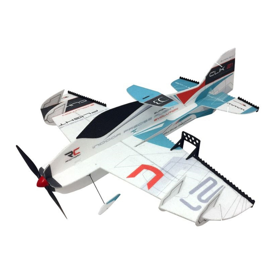
- Page 1 CLIK 21 MOTOR: 1x 14-19g / 40-60 Watt Outrunner RADIO: 4 channel ESC: 1x 6-12A ESC WINGSPAN: 33” SERVOS: 1x 8g-11g (ailerons LENGTH: 47” 2x 4g-6g (rudder and elevator) AUW: 120g to 130g PROP: 1x 8-9 inch depending components used www.twistedhobbys.com...
-
Page 2: Safety Notes
SAFETY NOTES Before assembling and flying this model, read carefully any instructions and warnings of other manufacturers for all the products you installed or used on your model, especially radio equipment and power source. Check thoroughly before every flight that the airplanes’ components are in good shape and functioning properly. -
Page 3: Warning Information
SHIPPING DAMAGE Twisted Hobbys checks each plane before shipping to ensure that each kit is in fine condition. We have no bearing on the condition of any component parts damaged by use, modi fication, or assembly of the model. Inspect the components of this kit upon receipt. If you find any parts damaged or missing, contact Twisted Hobbys immediately. -
Page 4: Kit Contents
kit contents Wing Parts Fuselage Parts Double check that you have all the above pictured items. Note - Some kits might have slight deviations from the above pictured items. DETAILED DESCRIPTIONS OF ITEMS WILL BE CALLED OUT IN THE BUILD STEPS www.twistedhobbys.com page 4 Rev: 2020.01.18.v01a... - Page 5 kit contents (cont.) Hardware and Small Carbon Carbon Bundle Contents Double check that you have all the above pictured items. Note - Some kits might have slight deviations from the above pictured items. DETAILED DESCRIPTIONS OF ITEMS WILL BE CALLED OUT IN THE BUILD STEPS www.twistedhobbys.com page 5 Rev: 2020.01.18.v01a...
- Page 6 Power Combo Details There are many different combinations of servos, motors, escs, props, etc. Above is a suggestion offered from Twisted Hobbys for good durability and weight management. *** THESE ARE OPTIONAL ITEMS - THEY ARE NOT INCLUDED IN THE KIT *** www.twistedhobbys.com...
- Page 7 TOOL AND ADHESIVES NEEDED Lighter Small Drill Bits Tape Measure and Ruler Black Sewing Thread Welders or Foam Tac Glue Hobby Knife w/new Blade Needle Nose Pliers Wire Cutters Tools shown and listed are suggestions only. Low Temp Hot Glue Gun Depending on your building technique you may not ...
- Page 8 the build CONSTRUCTION METHODS: Building surface should be at least 2ft x 4ft and at. Weights or some small heavy objects will be handy for holding things in place during the time glue is setting. Welders or FoamTac glue is used for FOAM TO FOAM joints. Thin and Medium CA can be used on the PLASTIC TO FOAM and CARBON TO FOAM joints.
- Page 9 Gently fold back all the control surfaces and let sit Always start your builds with a fresh Blade Locate the pcs shown and remove the scrap FoamTac will be used to attach the wings to fuse Apply a medium bead to the wing edge Tack Together, let sit for 60sec the join Repeat for the other wing Tack and Join like with the other side...
- Page 10 Mark the center Apply a med. bead of FoamTac to the leading edge ..all along for the length of the spar ..to the other wing tip Constrain the wing flat, Tack & Join Apply pressure for a minute or two for good joint Locate the 3x0.5x500 carbon piecs Test fit into the rearward slot from under side of wing Make sure it is flush, not sticking above...
- Page 11 Apply a med. bead of FoamTac into the slot Install the spar Push flush and wipe away an extra glue Constrain flat ..make sure it is flush, and let sit for a bit Locate - nose piece - two leading edge extensions Test fit - make sure slots will align Use the small index marks as an aid Apply FoamTac to the nose piece...
- Page 12 Tack & Join Apply FoamTac Tack & Join Other wing tip - apply FoamTac Tack & Join Locate the elevator and 3x0.2x300 carbon piece Test fit for length and flushness Apply a bead of FoamTac into the slit Install the spar and wipe away extra glue www.twistedhobbys.com page 12 Rev: 2020.01.18.v01a...
- Page 13 Make sure it is flush, then let sit for a bit Locate the fuselage assembly and elevator Apply a bead of FoamTac to the Elevator Tack & Join Constrain flat and let sit for a bit Locate two of the 0.8x500 rounds They go into the slits on the bottom edge of fuselage They will need to be trimmed to fit for length Install into the slit and snip to length...
- Page 14 You will have two small pieces left over Detail on how the wing spar and fuse spar meet up Remove the spars and apply glue in the slit Install the spars, wipe away any extra glue While the glue is wet - make sure fuse is straight Constrain flat and let sit for a bit Locate the servo you will use for the elevator It will install into the cutout in the horizontal section...
- Page 15 Grab the lower vertical fuselage section..and test fit it as shown Make sure the fit up is nice and square Also note that you want the front part flush When happy with the fit up remove and apply glue Make sure the main section is flat, and assemble Make sure the tabs and parts are fully seated While the glue is still wet make sure its all square...
- Page 16 Double check that the front is flush and let it all dry Locate the 4 pieces of 1x250mm round & half moons Make sure the cut out in the half moons fit the rod Notice the orientation of the fuselage cutouts The half moons install with the same orientation Apply some glue to the mating fuselage area And attach a half moon to each side of the fuselage...
- Page 17 Test fit the other rod as show, also in the pre cut slot The slots are small, clear them out if needed Test fit all four rods - No glue at this time Make sure the fuselage and wing are square And that the fuselage is nice and straight Cans could be used to help hold things in place Remove the rods and apply glue to the wing spot...
- Page 18 While the glue is wet, twist the rods a little..and apply a dab of glue to all the ends and let dry Locate the 5 pieces of 0.8x500 carbon rounds Cut Lengths and Item Numbers for 5x - 0.8x500 carbon spars www.twistedhobbys.com page 18 Rev: 2020.01.18.v01a...
- Page 19 Measure and cut per the previous picture Install #1 pieces as shown - No glue at this time Install #2 pieces as shown - No glue at this time Install #3 pieces as shown - No glue at this time Install #4 pieces as shown - No glue at this time Install #5 pieces as shown - No glue at this time Install #6 piece as shown - No glue at this time...
- Page 20 Also check along the side that it is square Once straight and square apply glue to all end points Let this dry completely before handling Locate the foam piece shown Separate them and grab the two matching parts Locate the 4 pieces 0.8x330mm carbon rounds Locate 2 pieces 3x0.2x100mm &...
- Page 21 Test fit the strip into the slot..and trim to length Make sure is fits down completely flush Grab the horn with the flange on the side shown Test fit it as shown with the flange over the strip Close up of how the flange fits over the strip Make sure the horn hole is over the hinge center When happy with the fit remove and apply glue...
- Page 22 Apply some glue to the horn And install with the flange over the strip Repeat for the other side and constrain it all flat Grab one of the foam pieces like shown Test fit and apply glue to the mating surfaces While the glue is still wet, make sure it is square Repeat for the other aileron Next grab the 4 carbon rounds (0.8x330mm)
- Page 23 Pre-cut slot by the horn Test fit one rod as shown Test fit the second rod as shown Make sure the gusset is square Glue the ends and where they cross over Do both sides - don't worry about extra for now EXTRA EXTRA Once the glue has set a little trim the extra off...
- Page 24 Fit the two outboard pieces in as shown Next glue the ends Repeat for the other aileron Constrain everything flat and let the glue dry Locate 2 pieces 1.5x220mm rounds and other items Stick the 2 pieces of 1.5mm round thru like shown They cross over in the middle And stick into the holes in the fuslage Cross them over in the middle like shown...
- Page 25 Next is the wheel hubs and axles Axle will install from this side Test fit and make sure it can go all the way in Test fit the other one Put some glue in the hole Install the axle This “slot” is for the gear strut It should slide all the way in as shown Secure with some glue www.twistedhobbys.com...
- Page 26 While the glue is still wet line up the axle Install the hub and axle - make sure they are even Drill out the center hole to 1.5mm (.062in) Slide the wheel on Repeat for the other side Locate the wheel pants and stiffener Separate the parts from each other Glue together with the nub INTO the hole in the foam Repeat for the other side...
- Page 27 Once it is dry install on to the axle Slide all the way on to capture the wheel Make sure the wheel can spin and add a dab of glue Repeat for the other side - Make them even Next locate the two #9 carbon rounds They go from where the struts cross to the nose There is a small slit - enlarge it some if needed Test fit into place...
- Page 28 Make sure the nose section is straight and square Glue the ends - Keep glue away from struts Double check that everything is square after gluing Constrain everything flat..and let it dry Aileron servo with double and differential horn Differential horn will install like pictured below Put a dab of glue on the stock horn and...
- Page 29 Find two small servo screws and install as shown Locate the adjustable rod ends Install them as shown below Picture of the underside Attach to the servo in orientation shown Locate snap links, tubing and 1x190mm carbon rods Put some glue on the end of the rod Attach it to the saddle area of the snap link Slide a short piece of shrink tubing over - let dry www.twistedhobbys.com...
- Page 30 Repeat for the other rod Grab your aileron servo If needed adjust the size of the cut out so it will fit Install as shown Make sure there is clearance on the other side too Secure with a bead of FoamTac View of aileron servo from the front of aircraft Grab the rudder servo you will be using Fit it into the slot - adjust size if needed...
- Page 31 Make sure there is clearance underneath as well Locate the upper fuselage and canopy pieces Apply a bead of FoamTac to the canopy Attache the two pieces Test fit the upper section to the fuselage assembly Make sure all the tabs can fully engage Trim a little around the servos if needed Make sure the fit up is nice and straight Remove and apply glue to the mating surfaces...
- Page 32 Fit the upper fuse section on and check for square Soda Cans can be used to hold everything in place Make sure it is square from all angles Locate the horns and 3x0.2x75mm strip Test fit in the slot the secure with glue Make sure it is all the way flush Next take the horn as shown below Put some glue on the horn and intall as shown...
- Page 33 Apply glue to the mating surfaces Mate the parts together and let glue dry Locate the two 3.0x0.2x150mm strips Test fit one of them into the rear vertical slot Should go all the way top to bottom and be flush Repeat for the front position Note how it goes in between the LG struts Check that everything is square...
- Page 34 When happy with fit remove and glue them both in Front and rear done - double check for square Get 2 snap links - tubing - two 0.8x500mm rods Tubing is cut from the left over from other rods Coat the end of the rod with FoamTac Attach link in saddle area, slide tubing on and heat ONLY ENOUGH TO SHRINK THE TUBING!
- Page 35 Locate the slot in the elevator Add some glue to the slit..install the horn with hole over the hinge line Locate small round guide holes, add a dab of glue Insert a guide into each one Grab one of the rods and slide thru the guides Use the rod to line up the guides while glue is wet Position the snap link as shown...
- Page 36 Make sure it snaps all the way in flush Locate the other rod you made And the remaining rod guides Locate the holes in the upper vertical fuse section There should be a total of 6 holes Add a dab of glue to each hole Install a rod guide into each Thread the control rod thru Line up all the rods for smooth operation...
- Page 37 Snap the link into the control horn hole Make sure it is flush Locate rods #7 and #8 #7 and #8 - test fit into pre-cut slits Add a dab of glue to the top of #7 Add a dab of glue to the top of #8, let them both dry Add a dab of glue to the bottom of each...
- Page 38 Add some glue to the back side of the mount..and the mating surface of the nose Press the mount onto the front as shown Locate the two parts shown Separate out the scrap area Add some glue to the mating surfaces Bring the pieces together and check for square With a sharp hobby knife slit the top tab Top tab slit...
- Page 39 Cantilizer fits to the back of the canopy Test fit as shown Make sure it is square and parallel When happy with the fit up, glue mating surfaces Attach... check for squareness..and parallel in all directions Locate the Side Force Generators (SFG) Cut out the scrap Slit the rearward tab www.twistedhobbys.com...
- Page 40 Only do the reward tabs Glue them on. Larger one closer to the wing tip Make sure they are square. Do both wings. Locate the trailing edge fences Separate and remove scrap Glue the longer one onto the aileron trailing edge And the shorter one to the elevator trailing edge Make sure they are all flush...
- Page 41 Locate the sheet shown Separate out and remove scrap Clear/Cut the holes shown in the wing There is an inner and out gusset, apply glue..and stick together making a left & right assembly Attach as shown Build the arms like shown Make sure they are perpendicular to flight direction Locate the hardware for the tail servos www.twistedhobbys.com...
- Page 42 Electronically center the rudder servo..thread control rod thru and mount to servo Center the control surface and lightly tighten screw Repeat the whole process for the elevator servo Locate the 2 aileron rods made earlier Locate the aileron control horn made earlier Electronically center servo and mount horn Thread the bare end thru the adjustable link...
- Page 43 Pinch with finger tips to snap into the hole Repeat for the other side Locate your motor Will mount to the front..with the included screws Attach with wires going to where ESC will be located Balance and attach a prop Locate ESC and Receiver Mount ESC and Receiver approx.
- Page 44 Find yourself a park that is out of the way with a little open space and tear it up, this plan is the perfect size..!! This completes the build, it’s design and construction should give you many hours of ying enjoyment. This airplane will serve you well, whether you are new to precision ying or are a seasoned veteran.
- Page 45 center of gravity and control throws Control Throws Ailerons: +/- 40 deg Rudder: +/- 50 deg 240mm Elevator: +/- 50 deg Expo and Dual Rates to suit Control Throws should be adjusted to flying style and adjusted to work with in the boundaries of the setup.
-
Page 46: Pre-Flight & Testing
If there is insufficient range or distort. Storage in a hot car could also cause damage. significant reduction with the motor running, resolve and re-test before flying. Be safe and enjoy, thank you again for purchasing a Twisted Hobbys’ Product! www.twistedhobbys.com page 46 Rev: 2020.01.18.v01a... -
Page 47: Tips And Tricks
TIPS AND TRICKS A good building surface is — drop ceiling“ panel from a local hardware store on a nice flat board Use parchment paper between the areas being glued and your work surface Heavy flat objects (like books, batteries, etc.) could be used to hold everything flat When resetting your radio, start with all the ATV‘s or throw volumes at 100%. - Page 48 notes and s/u Sheet www.twistedhobbys.com page 48 Rev: 2020.01.18.v01a...
Need help?
Do you have a question about the Clik 21 and is the answer not in the manual?
Questions and answers