
Related Manuals for Tyco 4100ES


Summary of Contents for Tyco 4100ES
- Page 1 SP1 Fire Indicator Panel 4100ES Fire Indicator Panel Operator’s Manual InfoAlarm Operator’s Manual Operator’s Manual LT0568 Iss 1.0...
- Page 3 4100ES Fire Indicator Panel Operator’s Guide Fire detectors in the building are grouped into zones (searchable areas). Zones can be Isolated by pressing the zone’s isolate pushbutton on the panel – this prevents an alarm from activating the panel outputs.
-
Page 4: Manufacturer
Tyco, Simplex, the Simplex logo, MAPNET II, IDNet, TrueAlarm, SmartSync, WALKTEST, MINIPLEX, and TrueAlert are trademarks of Tyco International Services AG or its affiliates in the U.S. and/or other countries. VESDA is a trademark of Xtralis Pty Ltd. -
Page 5: Product/Site
Telephone Service Contract Cautions & Some of the operation of the 4100ES, as described in this manual, is dependent on custom Warnings configuration as performed by the field engineer. If the configuration is not as per the recommended template, then the operation may differ and compliance to AS 4428.1 may be invalid. -
Page 6: Table Of Contents
Introduction ....................... 3-1 In this Chapter ......................3-1 Acknowledging Fault or Isolate Conditions ............3-2 How the 4100ES Indicates the Presence of a Fault or Isolate condition ....3-2 What Acknowledge Does ..................3-2 Panel Operating Procedure – Fault Condition ............3-3 Resetting Fault Conditions .................. - Page 7 Overview ........................4-2 Selecting Points directly ................... 4-2 Chapter 5 Testing and Controlling Points ........5-1 Introduction ....................... 5-1 In this Chapter ......................5-1 Alarm and Fault Test for Zones ................5-2 Alarm Test ........................ 5-2 Fault Test ........................5-2 Isolating and De-isolating Zones ................5-3 Overview ........................
- Page 8 Procedure.......................11-3 Chapter 12 Maintenance Procedures .......... 12-1 Introduction ......................12-1 In this Chapter ......................12-1 AS 1851 Testing – Guide for 4100ES – Specific Test Methods ......12-1 Monthly Tests ......................12-2 Monthly Tests ......................12-2 6 Monthly Tests ......................12-2 Annual Tests ......................12-3 Annual Tests ......................12-3...
-
Page 9: Chapter 1 Overview
Chapter 1 Overview Introduction This chapter provides an overview of the 4100ES operator interface and describes the normal appearance of the operator interface. In this Chapter Refer to the page number listed in this table for information on a specific topic. -
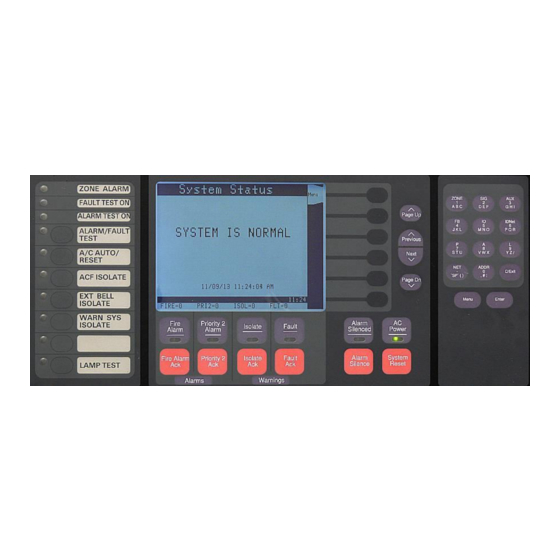
Page 10: Typical Panel Layout
Typical Panel Layout Overview The 4100ES is supplied with an InfoAlarm graphic Operator Interface plus one or more Expansion Bays in a suitably sized cabinet. Refer to Figure 1-1. The Zone Isolate modules are fitted into the Expansion bays from left to right. The first zone is at the top of the leftmost module. -
Page 11: Basic System Description
The InfoAlarm operator interface, shown in Figure 1-2 and described in Table 1-1, allows a system operator to control and monitor the site-specific components connected to the 4100ES. Function/ Numeric... -
Page 12: Overview
Basic System Description, Continued Overview (continued) Table 1-1. Components of the Operator Interface (continued) LED/Key Description Refer To Warnings - Isolation and Fault indicate when abnormal, non-fire conditions occur. Isolate LED When any zone is isolated, this LED turns on and the buzzer sounds until Chapter 3 Isolate Ack Key Isolate Ack is pressed. -
Page 13: Control Keys & Indicators
WARN SYS ISOLATE - When this indicator is on the Warning System is prevented from operating. LAMP TEST – pressing this tests all the indicators on the front of the 4100ES panel. -
Page 14: Normal Appearance Of Operator Interface
Normal Appearance of Operator Interface Description The 4100ES operator interface panel shows the following under normal conditions: Green AC Power LED is ON, indicating the panel is receiving AC Power. All other LEDs are off. The alphanumeric display reports that the system is normal and shows the current... -
Page 15: Introduction
An alarm condition occurs when an actuating device (such as a manual call point, smoke detector, etc.) activates. The 4100ES indicates the presence of the alarm condition through messages it displays on the alphanumeric display, by illuminating the ALARM indicator LEDs, and by activating the building’s EWS and external bell. -
Page 16: Acknowledging Alarms
Acknowledging Alarms What the System When the first alarm condition is detected by the 4100ES, the panel does the following to Does When an indicate the presence of the alarm: Alarm Occurs Red Fire Alarm and common Zone Alarm LED indicators flash. -
Page 17: Procedure
Acknowledging Alarms, Continued Procedure Use the following procedure to acknowledge alarm(s): Unlock and open the enclosure door. Press the <FIRE ALARM ACK> key. Pressing the ACK key causes the following to occur: Buzzer silences. Fire Alarm indicator changes from flashing to steady ON. ... -
Page 18: Isolating (Silencing) The Warning System Or External Bell
The External Bell turns OFF. If another alarm occurs, the 4100ES will not activate the external bell again until it is de- isolated. Do this by pressing the <EXT BELL ISOLATE> key again so that the EXT BELL ISOLATE indicator turns OFF When the alarms in the panel have been reset, leave the external bell de-isolated. -
Page 19: Isolating Acf Outputs
Overview The Ancillary Control Facility (ACF) consists of relay outputs which can be used to control equipment which is not part of the 4100ES fire alarm system, such as shutting down air conditioning or returning lifts to a certain floor. -
Page 20: Resetting Alarms
Resetting Alarms Overview The Alarm state and some Fault conditions latch within the panel so they can be acknowledged and viewed. When the latched states are no longer required they can be reset. The condition that caused each point to go into alarm must be cleared before the system can reset to the normal state, e.g., smoke cleared from smoke detectors, glass replaced in manual call point. -
Page 21: Resetting Air Conditioning Controls
When a zone alarm occurs, among the other alarm indications, the A/C AUTO indicator lights to show that the 4100ES has taken control of the air conditioning system. This operation remains in effect even after all alarms have been cleared and the 4100ES system has been reset and is back to normal. -
Page 22: Procedure
Displaying Event Time Procedure When viewing the lists of Alarms or Faults or Isolates, the time of any event can be shown by highlighting the event and pressing the Event Time soft key. Press <Fire Alarm Ack>, or <Isolate Ack> or <Fault Ack> to display the desired list. Use <Previous>, <Next>, <Page Up>... -
Page 23: Chapter 3 Managing Fault And Isolate Conditions
Fault conditions are used to indicate something wrong, e.g., the presence of a field wiring problem (circuit break, short or ground), somewhere between the 4100ES and one of its points. Faults are also used to indicate a problem with the option cards, power supplies, network card, etc., in the 4100ES. -
Page 24: Acknowledging Fault Or Isolate Conditions
Acknowledging Fault or Isolate Conditions How the 4100ES When a Fault or Isolate condition is present in the 4100ES, the operator interface does the Indicates the following: Presence of a Fault or Isolate condition The yellow “FAULT” or “ISOLATE” indicators flash. -
Page 25: Panel Operating Procedure - Fault Condition
Acknowledging Fault or Isolate Conditions, Continued Panel Operating Unlock and open the panel door. The yellow Fault or Isolate indicator (LED) will be Procedure – Fault flashing and the sounder (buzzer) sounding. Condition Press the <FAULT ACK> or <ISOLATE ACK> key as appropriate. An acknowledgement message is displayed (this example for Isolate): Figure 3-2. -
Page 26: Viewing Fault Or Isolate Conditions
Viewing Fault or Isolate Conditions Overview You can view the list of acknowledged Fault or Isolate conditions at any time: Press the <FAULT ACK> or <ISOLATE ACK> key to display the Fault or Isolate list. The first Fault or Isolate condition in the list appears at the top of the display. Figure 3-3. -
Page 27: Chapter 4 Selecting Points For Status Or Control
Chapter 4 Selecting Points for Status or Control Introduction Many of the operations that can be accomplished from the operator interface first require you to select the point on which you want to perform the operation. Points can be selected in one of two ways: ... -
Page 28: Selecting Points With The Function/Numeric Keypad
Selecting Points with the Function/Numeric Keypad Overview The Function/Numeric Keypad, shown in Figure 4-1 below, allows you to quickly select points. For example, pressing the AUX key (key also labelled 3) selects the auxiliary relay point category. After selecting a category, the points of that type are displayed on the screen. You can type the number of the desired point directly, or scroll through the list to find it. -
Page 29: Selecting Points Directly
Selecting Points with the Function/Numeric Keypad, Continued This example shows IDNet point M1-20 being selected. Selecting Points directly Press the <IDNet> key (the 6 key). The display shows the first IDNet point in the panel and puts (continued) “M” in the black entry bar near the bottom of the display: Figure 4-2. - Page 30 Table 4-1. Selecting Point Types Function/Numeric Keypad Press this Key Screen shows Data to Enter First on Keypad ZONE – allows you Points list with the first <zone number> on the numeric keypad, or to select a Monitor monitor zone highlighted. scroll through the list of points.
-
Page 31: Chapter 5 Testing And Controlling Points
Chapter 5 Testing and Controlling Points This chapter describes using the panel’s action keys (ALARM TEST, On, Off, etc.) to test and Introduction control zones and points. In this Chapter Refer to the page number listed in this table for information on a specific topic. Topic See Page # Alarm and Fault Test for Zones... -
Page 32: Alarm And Fault Test For Zones
Alarm and Fault Test for Zones Alarm Test Alarm Test forces a zone into the alarm state. Once the zone is in alarm, you can check to see if the system reacts in the way that it has been programmed, i.e., do signals sound in the correct manner? do relays function correctly? etc. -
Page 33: Isolating And De-Isolating Zones
Isolating and De-isolating Zones Overview This section describes isolating and de-isolating zones. Isolating a zone does not prevent any of the points within the zone from going into the alarm state, but does prevent the activation of any outputs that are programmed to operate when the zone is in alarm. Pressing a zone’s ISOLATE key toggles its Isolate status. -
Page 34: Disabling And Enabling Points
Disabling and Enabling Points Disabling and Enabling Points Situations such as a malfunctioning detector causing false alarms, or an activated detector that Overview prevents the system from being reset, can be temporarily overcome by disabling that particular point. Disabling a point allows the system to be reset while repairs are being made. It takes the point “offline”. -
Page 35: Enabling A Point
Enabling a To enable a point: Point Select the disabled point that you want to enable, e.g., by selecting the point directly, or by scrolling through the Fault list to find it. Press the <ENABLE> soft key. Figure 5-6. Count down message during enabling a point Note: The system displays a message indicating that the point will be enabled in 60 seconds, and counts down. -
Page 36: Turning A Point On Or Off
Turning a Point ON or OFF Overview It may be necessary during testing and maintenance of the system to force outputs on or off, e.g., alarm devices and relays. Turning an output point off is effectively isolating that output. Once turned off, the output will not turn on, even if an alarm condition that is programmed to turn it on occurs. -
Page 37: Returning A Point To Automatic Operation
To force this update, do a warm restart of the system (see Chapter 9). A loud buzzer is used in the Australian 4100ES to meet the requirements of AS 4428 (70dB at Sounder (Buzzer) 1m with the door closed). -
Page 39: Chapter 6 Displaying And Modifying Detailed Point Attributes
Chapter 6 Displaying and Modifying Detailed Point Attributes Introduction This chapter describes displaying and modifying the detailed attributes of a point. In this Chapter Refer to the page number listed in this table for information on a specific topic. Topic See Page # Detailed Point Attributes... -
Page 40: Select A Point
Detailed Point Attributes Select a Point Points can be selected in two ways: through the Alarm, Fault, or Isolate list, or with the Function/Numeric keypad. Refer to Chapter 4 for how to select a point. When the point is selected, the display shows a list of the point’s attributes. Different types of See the Attributes points will show a different list of attributes. -
Page 41: Summary Of Display-Only Attributes
Detailed Point Attributes, Continued Summary of Display- Some attributes can be changed via this display, if you are logged in at an appropriate access Only Attributes level. The softkeys at the side of the display show the available options. Table 6-2 shows the attributes that can be modified using the operator interface. Table 6-2. -
Page 42: Example Of Display-Only Attributes
Detailed Point Attributes, Continued The following example shows the attributes for signal point SIG4. Example of Display- Only Attributes The SIG4 point is selected from the points list as described in Chapter 5. When the <Select Item> soft key is pressed, the attribute information is displayed: Pressing the <Disable>... -
Page 43: Chapter 7 Setting Access Levels And Logging In
Chapter 7 Setting Access Levels and Logging In Introduction This chapter describes logging in and out at different access levels. In this Chapter Refer to the page number listed in this table for information on a specific topic. Topic See Page # Logging In and Out of the System... -
Page 44: Logging In And Out Of The System
Logging In and Out of the System Introduction The 4100ES uses four access levels, referred to by the numbers 1 through 4, to control what operators can do with the system. The system typically operates at access level 1, which allows an operator to accomplish basic tasks without logging in to the system. -
Page 45: Log Out Procedure
Logging In and Out of the System, Continued Log In Procedure If the passcode entered in Step 4 is correct, the following message is shown: (continued) Log Out Procedure Failure to log out may allow unauthorized personnel access to the various protected functions. If no keypad activity is detected for ten minutes, the system automatically returns to Level 1 access. -
Page 47: Chapter 8 Viewing And Clearing Historical Logs
Chapter 8 Viewing and Clearing Historical Logs Introduction When an abnormal condition occurs, a record of the event is placed in one of two logs generated by the system, depending on the nature of the condition. These logs are: Historical Alarm Log ... -
Page 48: Viewing And Clearing The Historical Alarm And Fault Logs
Viewing and Clearing the Historical Alarm and Fault Logs Viewing Logs The Historical Alarm and Fault Logs can be viewed from the 4100ES operator interface: Press the <MENU> key. Move the highlight to the Logs option, and press <ENTER> or <Select Item>. -
Page 49: Clearing The Logs
Use the <NEXT> or <PREVIOUS> or <PAGE UP> or <PAGE DN> keys to scroll through the list of logged events, until the desired event is shown on the display. Note: Pressing the <PREVIOUS> key first causes the most recent event to be displayed. -
Page 51: In This Chapter
Chapter 9 Service-Related Operations Introduction This chapter describes service-related status and control procedures. In this Chapter Refer to the page number listed in this table for information on a specific topic. Topic See Page # Setting Time and Date Displaying Software Revision Viewing Card Status Information Displaying Network Node Information Lamp Test... -
Page 52: Setting Time And Date
Setting Time and Date Press the <MENU> key. Scroll the highlight to Clock Set time and date?, and press Procedure <Select item> or <ENTER>. Enter the new date in the Set Clock display. Use the <Delete> softkey to correct mistakes. Press <OK> when the new date is entered. If the date is already correct, just press <OK>... -
Page 53: Displaying Software Revision
Displaying Software Revision Procedure Follow these steps to display software revision information: 1. Press the MENU key to show the Main Menu. Scroll the highlight down to “Panel Info: Stat and Revisions?”. Press <Select Item> soft key or <ENTER> to show the Panel Menu: Scroll the highlight down to “Panel Info: Stat and Revisions?”. -
Page 54: Procedure
Displaying Software Revision, Continued Procedure (Cont’d) Highlight the “Revision Show System Revisions” and press <Select Item> soft key or <ENTER> to show the System Revisions: Interpret this information as follows: SYS REV: Specifies the revision of the executive software (operating firmware of the FIP) loaded in the panel. -
Page 55: Procedure (Cont'd)
Viewing Card Status Information Overview Every card, including the Master Controller and all option cards, has a series of Card Status Points associated with it. For the SPS (System Power Supply) these points include System Voltage, System Current, and Battery Voltage. Procedure Press the <MENU>... -
Page 56: Viewing Card Status Information, Continued
Viewing Card Status Information, Continued Power Some cards require several screens to display all the status information. This is particularly the Supply/Charger case for the SPS, where the second screen shows the system and battery voltages and currents. Voltage and Current Readings If necessary, scroll down to see hidden information. -
Page 57: Displaying Network Node Information
Displaying Network Node Information Overview Networked systems consist of multiple panels linked via a 4120 network. Each panel has a programmer-defined node number, used to identify the panel on the network. The following section describes how to determine a panel’s node number. The node number is required when selecting a network point. -
Page 58: Displaying Network Node Information, Continued
Displaying Network Node Information, Continued 3. In the Network Info Menu, there are three options: Highlight the desired option and press <Select Item> soft key or <ENTER>. NodeID – show the node name of this panel. Node Status – shows the network configuration version and the on-line status of all nodes in the network. -
Page 59: Lamp Test
The “LAMP TEST” push-button on the operator interface is used for identifying local lamp Procedure (LED) failures within the system. LEDs on the 4100ES operator interface and Switch/LED Display Modules illuminate. Perform the following procedure to check correct LED or LCD operation: 1. -
Page 60: Procedure
Warm Restart of the System Overview A Warm Restart is used to reset some higher level operations of the 4100ES, such resetting system points to their default values, and clearing service-related fault conditions. The Warm Restart function is not required for normal operation of the 4100ES panel, and the option to restart is visible and available only if you are logged in at an appropriate access level (see Chapter 7). -
Page 61: Displaying Idnet & Mapnet Device Status
IDNet device address, press the <MORE> soft key on the operator interface panel to display additional device information. IDNet Point Each IDNet device must have a point address in order to communicate with the 4100ES FIP. Addressing These point addresses along with their custom labels are located in the Programmers Report. - Page 62 Displaying IDNet & Mapnet Device Status, Continued The point name is called up, using the procedure described in Chapter 4. Currently, the subpoint 0 is highlighted in the list of points. Press <Select Item> softkey or <ENTER> for the 0 subpoint to show the basic information about this point.
-
Page 63: Truealarm Sensor Display Values
Through the use of a system pseudo point all new peak values per sensor can be stored in the history fault log and printed on the optional 4100ES system printer. Printing of peak values is done at the time the peak value is received at the FIP. This peak value is helpful in determining if a sensor should be made more or less sensitive. -
Page 65: Chapter 10 Walk Test Procedures
Chapter 10 Walk Test Procedures Introduction The following test features can be used when commissioning after the system is installed, and during periodic testing as required by code. Refer to Chapter 12, Maintenance Procedures for detail on these. In this Chapter Refer to the page number listed in this table for information on a specific topic. -
Page 66: Walk Test
4100ES has the ability to briefly activate sounders to confirm detection device operation. However, the tone generators or EWIS used as the warning system in Australian installations will not reliably work with these brief activations. -
Page 67: Zone Coding Option
(see Chapter 7). When the 4100ES system is placed in Walk Test™ mode, any zone in the active Walk Test™ group(s) can be tested in any order. If zone coding is enabled, there is an advantage in testing all devices within one zone before going on to the next zone. -
Page 68: Walk Test™Procedures
Walk Test™Procedures How to Enter Walk Log into the 4100ES panel at the necessary access level (Level 2 or higher). Test Mode In the main menu screen on the InfoAlarm, scroll the highlight to the Service/Diagnostics option and press the <Select Item> softkey or <ENTER>: In the Diagnostics Menu, scroll the highlight to the Walktest option and press the <Select Item>... -
Page 69: How To Enter Walk Test Mode
Walk Test™Procedures, Continued The Walk Test™ Settings menu allows the settings for each group to be individually adjusted. How to Enter Walk Use the <Next Group> or <Prev Group> soft keys to step through the Walk Test groups 0 to 7. Test Mode The list rolls around in either stepping direction. - Page 70 Set all the Walk Test groups to Off. Log out of the 4100ES system. Inform the customer or site management when system testing is completed. If Walk Test is not specifically turned off as above, the system will automatically abort Walk Test after 90 minutes of inactivity.
-
Page 71: Chapter 11 Printing Reports
Chapter 11 Printing Reports Introduction This chapter describes printer options and how to print a report. In this Chapter Refer to the page number listed in this table for information on a specific topic. Topic See Page # Selecting Report 11-2 Printing a Report 11-3... -
Page 72: Selecting Report
Selecting Report Available Options The 4100ES includes two printer options: Select Report Printer and Terminate Current Report. Press the MENU key to show the Main Menu. Follow these steps to select report printing options: Scroll the highlight down to “Print Reports”. Press <Select Item> soft key or <ENTER>, to show the Reports Menu: Select the desired report –... -
Page 73: Printing A Report
The report prints on the panel’s report printer if this is defined in the configuration. Procedure. The report output can also be conveniently captured via the Ethernet connection to the service port on the 4100ES. Refer to LT0565 4100 Fault Finding Guide for details about this. 11-3... -
Page 75: In This Chapter
AS 1851 Testing – The 4100ES and its associated equipment must be tested at regular intervals. Test criteria, Guide for 4100ES – service intervals, and record keeping requirements are specified in the appropriate Standard, the Specific Test latest being AS 1851:2012. - Page 76 Monthly Tests Monthly Tests Monthly Tests AS 1851 Description Action Required and Pass/Fail Criteria Test Facility, Item No. Procedure, Notes Fire Alarm SIMULATE an alarm condition and confirm that all Refer Chapter 5 Alarm required common or general visual and audible and Fault Test for indications operate and the external alarm is Zones.
- Page 77 The normal battery test facility capacity. in the 4100ES does not meet Verify that the measured currents are the the requirements of this test. same as recorded in the baseline data. Refer to the notes following this table.
- Page 78 Annual Tests, Continued CAUTION: TAKE PRECAUTIONS TO PREVENT UNACCEPTABLE VENTILATION Annual Tests - SYSTEM CHANGES Smoke Hazard Management Additional Tests to be Done Annually - Smoke Hazard Management Systems Systems AS 1851 Description Action Required and Pass/Fail Test Facility, Procedure, Item No.
-
Page 79: Five Year Tests
FIP. Power Where the system is monitored, This test requires equipment supply REDUCE the CIE operating voltage to external to the 4100ES. supervision trigger a power supply Refer to the notes following this supervision fault and CONFIRM that it table. -
Page 80: Battery And Keypad Test Details
Battery and Keypad Test Details The 4100ES Fire Alarm Panel has no provision for load discharge testing of the battery at the Battery Load levels required for yearly testing to AS 1851:2012. Discharge Testing (AS 1851:2012 A load discharge method separate from the panel must be arranged in order to meet this Item 3.7)