Advertisement
Technical Services: Tel: (800) 381-9312 / Fax: (800) 791-5500
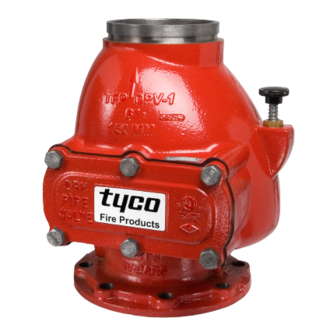
Model DPV-1 Dry Pipe Valve, External Resetting
2-1/2 thru 6 Inch (DN65 thru DN150)
250 psi (17,2 bar)
General
Description
®
The Tyco
Model DPV-1 Dry Pipe
Valves are differential valves used to
automatically control the flow of water
into dry pipe fire protection sprinkler
systems upon operation of one or
more automatic sprinklers. The DPV-1
also provides for actuation of fire
alarms upon system operation. The
Model DPV-1 features are as follows:
• External reset.
• 250 psi (17,2 bar) pressure rating.
• Unique offset single clapper design
enabling a simple compact valve to
minimize installation labor.
• Ductile iron construction to ensure a
lightweight valve to minimize ship-
ping cost.
• A variety of inlet and outlet connec-
tions.
• Compact, semi-preassembled or
fully assembled, and easy to operate
valve trim.
• Simple reset procedure through the
elimination of priming water.
Dry pipe sprinkler systems are used in
unheated warehouses, parking ga-
rages, store windows, attic spaces,
loading docks, and other areas ex-
posed to freezing temperatures, where
water filled pipe cannot be utilized.
When set for service, the dry pipe
sprinkler system is pressurized with air
(or nitrogen). The loss of pressure
through an operated automatic sprin-
kler in response to heat from a fire
permits the DPV-1 Dry Pipe Valve to
open and allow a flow of water into the
sprinkler system piping. Table B es-
tablishes the minimum required sys-
tem air pressure that includes a safety
factor to help prevent false operations
that might occur due to water supply
fluctuations.
Page 1 of 20
Available End Connections and Sizes
End Connection
Flange x Flange
Flange x Groove
Groove x Groove
Available
N/A
Not Available
WARNING
The Model DPV-1 Dry Pipe Valves de-
scribed herein must be installed and
maintained in compliance with this
document, as well as with the applica-
ble standards of the National Fire Pro-
tection Association, in addition to the
standards of any other authorities hav-
ing jurisdiction. Failure to do so may
impair the performance of these de-
vices.
AUGUST, 2007
Nominal Valve Size
2-1/2 Inch
3 Inch
(DN65)
(DN80)
(DN100)
N/A
N/A
N/A
N/A
The owner is responsible for maintain-
ing their fire protection system and de-
vices in proper operating condition.
The installing contractor or manufac-
turer should be contacted with any
questions.
4 Inch
6 Inch
(DN150)
TFP1020
Advertisement
Table of Contents

Related Manuals for Tyco DPV-1


Summary of Contents for Tyco DPV-1
- Page 1 Technical Services: Tel: (800) 381-9312 / Fax: (800) 791-5500 Model DPV-1 Dry Pipe Valve, External Resetting 2-1/2 thru 6 Inch (DN65 thru DN150) 250 psi (17,2 bar) General Description ® The Tyco Model DPV-1 Dry Pipe Valves are differential valves used to...
- Page 2 (c) Reset Plunger Parts Kit Includes Items: 11 through 18 ..92-309-1-405 FIGURE 1 — Part 1 of 2 MODEL DPV-1 DRY PIPE VALVES 2-1/2, 3, and 4 INCH (DN65, DN80, and DN100) — ASSEMBLY —...
- Page 3 ..92-309-1-604 (c) Reset Plunger Parts Kit Includes Items: 14 through 21 ..92-309-1-405 FIGURE 1 — Part 2 of 2 MODEL DPV-1 DRY PIPE VALVES 6 INCH (DN150) — ASSEMBLY —...
-
Page 4: Technical Data
• Model AMD-3 Nitrogen Mainte- Dry Pipe Valve: Figure 7, and the Valve Trim is illus- nance Device (high pressure reduc- The Model DPV-1 Dry Pipe Valves are trated in Figures 4, 5, and 6. The Valve ing type). for vertical installations (flow going... - Page 5 8.9 feet for the 4 inch valve at at typical flow rate of 600 GPM 22 feet for the 6 inch valve at a typical flow rate of 1500 GPM FIGURE 2 MODEL DPV-1 DRY PIPE VALVES — NOMINAL PRESSURE LOSS VERSUS FLOW —...
-
Page 6: Operating Principles
Also, with the Clapper Assembly open, Pressure, Range, the intermediate chamber is pressur- The Model DPV-1 Dry Pipe Valve is a ized and water flows through the alarm differential type valve that utilizes a port (Ref. Figure 3B) at the rear of the... - Page 7 ISO THREADED PORTS SHUT OFF SHUT OFF FIGURE 3D FIGURE 3E DRAIN POSITION RESET POSITION FIGURE 3 — Part 1 of 2 MODEL DPV-1 DRY PIPE VALVES 2-1/2, 3, and 4 INCH (DN65, DN80, and DN100) — SET AND OPEN POSITIONS —...
- Page 8 PORT ASSEMBLY RESEATED WATER SUPPLY WATER SUPPLY SHUT OFF SHUT OFF FIGURE 3D FIGURE 3E DRAIN POSITION RESET POSITION FIGURE 3 — Part 2 of 2 MODEL DPV-1 DRY PIPE VALVES 6 INCH (DN150) — SET AND OPEN POSITIONS —...
- Page 9 ..92-343-1-007 Reducing Tee ..CH: Common Hardware FIGURE 4 — Part 1 of 2 2-1/2 and 3 INCH (DN65 and DN80) MODEL DPV-1 DRY PIPE VALVES — EXPLODED VIEW OF VALVE TRIM —...
- Page 10 (NORMALLY (NORMALLY WATER SUPPLY 3/4 INCH NPT CLOSED) CLOSED) PRESSURE CONNECTION GAUGE TO DRAIN FIGURE 4 — Part 2 of 2 2-1/2 and 3 INCH (DN65 and DN80) MODEL DPV-1 DRY PIPE VALVES — ASSEMBLY PROCEDURE FOR VALVE TRIM —...
- Page 11 ..92-343-1-007 Reducing Tee ..CH: Common Hardware FIGURE 5 — Part 1 of 2 4 INCH (DN100) MODEL DPV-1 DRY PIPE VALVES — EXPLODED VIEW OF VALVE TRIM —...
- Page 12 SLOPE ASSEMBLY B DOWN TOWARD CLOSED) CONNECTION BACK OF VALVE TO FACILITATE TO DRAIN SUFFICIENT LOW BODY DRAINAGE. FIGURE 5 — Part 2 of 2 4 INCH (DN100) MODEL DPV-1 DRY PIPE VALVES — ASSEMBLY PROCEDURE FOR VALVE TRIM —...
- Page 13 ..1/4" x 3" Nipple ..CH: Common Hardware FIGURE 6 — Part 1 of 2 6 INCH (DN150) MODEL DPV-1 DRY PIPE VALVES — EXPLODED VIEW OF VALVE TRIM...
- Page 14 TEST VALVE IDENTIFICATION. CONNECTION WATER SUPPLY (NORMALLY TO DRAIN ROUTE 1/4" TUBING TO DRIP PRESSURE CLOSED) FUNNEL. GAUGE FIGURE 6 — Part 2 of 2 6 INCH (DN150) MODEL DPV-1 DRY PIPE VALVES — ASSEMBLY PROCEDURE FOR VALVE TRIM —...
- Page 15 11-1/2" 7-1/4" 15" 14-3/4" (290 mm) (190 mm) (380 mm) (375 mm) 6 INCH (DN150) VALVE 18-3/4" 16" (475 mm) (406.4 mm) FxF, FxG, or GxG 4-1/2" (115 mm) FIGURE 7 MODEL DPV-1 DRY PIPE VALVE — INSTALLATION DIMENSIONS —...
-
Page 16: Installation
Air Supply Control Valve The DPV-1 Valve and associated trim clockwise for a lower pressure setting. (Fig. 4, 5, or 6). If the DPV-1 is must be maintained at a minimum tem- After verifying the desired pressure equipped with a Dry Pipe Valve Accel- perature of 40°F/4°C. -
Page 17: Care And Maintenance
The following procedures and inspec- Step 8. Refer to Table B and then tions should be performed as indi- Step 5. Reset the DPV-1 Valve in ac- restore the system to the normal sys- cated, in addition to any specific re-... -
Page 18: Limited Warranty
Step 1. Make sure that the Seat Ring is clean and free of any nicks or signifi- cant scratches. Products manufactured by Tyco Fire & Building Products (TFBP) are war- Step 2. Remove the Clapper Assem- ranted solely to the original Buyer for... -
Page 19: Ordering Procedure
Standard Galvanized DPV-1 Trim Replacement Trim Parts : Ordering (Ref. Figure F): Specify: (description) for use with Specify: 2-1/2 and 3 Inch DPV-1 Semi- (specify size) Model DPV-1 Dry Pipe Procedure Preassembled Galvanized Trim, Valve, P/N (see Figure 4, 5, or 6, as P/N 52-309-2-005. - Page 20 Dia. Groove ... . P/N 52-309-1-315 F x F, ISO Flange x ISO Flange... . . P/N 52-309-1-115 TYCO FIRE & BUILDING PRODUCTS, 451 North Cannon Avenue, Lansdale, Pennsylvania 19446...
Need help?
Do you have a question about the DPV-1 and is the answer not in the manual?
Questions and answers