Tyco DV-5 Manual
Deluge valve, diaphragm style, 1-1/2 thru 8 inch dn40 thru dn200, deluge system - electric actuation
Hide thumbs
Also See for DV-5:
- Manual (32 pages) ,
- Instruction manual (17 pages) ,
- General description manual (14 pages)
Table of Contents
Advertisement
DV-5 Deluge Valve, Diaphragm Style,
1-1/2 thru 8 Inch (DN40 thru DN200),
Deluge System — Electric Actuation
General
Description
The DV-5 Deluge Valve (described in
Technical Data Sheet TFP1305) is a
diaphragm style valve that depends
upon water pressure in the Diaphragm
Chamber to hold the Diaphragm closed
against the water supply pressure.
When the DV-5 Valve is set for service,
the Diaphragm Chamber is pressurized
through the trim connections from the
inlet side of the system's main con-
trol valve, for example an O.S.&Y. gate
valve or butterfly valve (Ref. Figures 1
and 4).
Operation of an electrical device such
as a heat sensitive thermostat, smoke
detector, or electrical manual control
station signals the Deluge Valve Re-
leasing Panel to energize the Solenoid
Valve. In turn, the energized Solenoid
Valve opens to release water from the
Diaphragm Chamber faster than it can
be replenished through the 1/8 inch
(3,2 mm) restriction provided by the
Model ASV-1 Automatic Shut-Off Valve
in the diaphragm supply connections
(Item 5 - Fig. 3A and 5, also described
in Technical Data Sheet TFP1384). This
results in a rapid pressure drop in the
Diaphragm Chamber and the force
differential applied through the Dia-
phragm that holds it in the set position
is reduced below the valve trip point.
The water supply pressure then forces
the Diaphragm open permitting water
to flow into the system piping, as well
as through the Alarm Port to actuate
the system alarms.
As water flows into the system, the pi-
lot chamber of the Model ASV-1 Auto-
matic Shut-Off Valve (Item 5 - Fig. 3A
and 5) becomes pressurized and the
ASV-1 automatically shuts off the di-
aphragm chamber supply flow to the
DV-5 Diaphragm Chamber. Shutting
off the diaphragm chamber supply flow
prevents the DV-5 Diaphragm Chamber
from becoming re-pressurized, there-
by preventing inadvertent closing of the
DV-5 during a fire (as may be the case
should the Solenoid Valve become de-
energized after its initial operation).
Page 1 of 14
NOTICE
The DV-5 Deluge Valve with Electric
Actuation Trim described herein must
be installed and maintained in compli-
ance with this document, as well as
with the applicable standards of the
National Fire Protection Association, in
addition to the standards of any other
authorities having jurisdiction. Failure
to do so may impair the performance
of these devices.
The owner is responsible for main-
taining their fire protection system
and devices in proper operating con-
dition. Contact the installing contrac-
tor or product manufacturer with any
questions.
OCTOBER 2014
Worldwide
www.tyco-fire.com
Contacts
TFP1320
Advertisement
Table of Contents

Related Manuals for Tyco DV-5


Summary of Contents for Tyco DV-5
- Page 1 DV-5 Diaphragm Chamber from becoming re-pressurized, there- by preventing inadvertent closing of the DV-5 during a fire (as may be the case should the Solenoid Valve become de- energized after its initial operation). Page 1 of 14...
- Page 2 TFP1320 Page 2 of 14 DV-5 Deluge Valve Water Supply Pressure Gauge Water ow Pressure Alarm Switch (Shown at Rear of Valve) Main Control Valve (N.O.) Diaphragm Chamber Pressure Gauge Water Motor Alarm (Optional) Diaphragm Chamber Supply Control Valve (N.O.) System Drain Valve (N.C.)
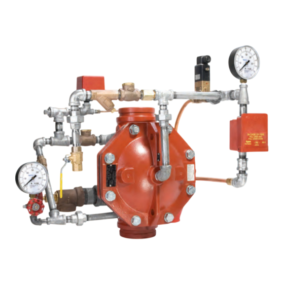
- Page 3 TFP1320 Page 3 of 14 Water Supply Pressure Gauge DV-5 Deluge Valve Water Motor Alarm (Optional) (Shown at Front of Valve) Main Control Valve (N.O.) Solenoid Valve Diaphragm Chamber Pressure Diaphragm Chamber Supply Deluge Valve Releasing Panel Gauge (Shown at Front of Valve) Control Valve (N.O.)
-
Page 4: Technical Data
• Water Supply Pressure Gauge life of the DV-5 Valve and Valve Trim. sitive thermostats, smoke detectors, • Diaphragm Chamber Pressure Gauges. Bronze bourdon and/or electric manual pull stations. - Page 5 Valve Port identi cation. Route all Tubing to Drip Funnel, Item 14. FIGURE 3A (1 OF 3) 1-1/2 AND 2 INCH (DN40 AND DN50) DV-5 DELUGE VALVES EXPLODED VIEW OF VERTICAL ELECTRIC ACTUATION TRIM Y-Strainer. Bronze body per ASTM Pipe Fittings. Galvanized mallea- B584 and Type 304 stainless steel ble iron per ANSI B16.3 or cast iron...
- Page 6 DV-5 DELUGE VALVE See Figure 2 of TFP1305 for SHOWN Valve Port identi cation. Route all Tubing to Drip Funnel, Item 15. FIGURE 3A (2 OF 3) 3 INCH (DN80) DV-5 DELUGE VALVE EXPLODED VIEW OF VERTICAL ELECTRIC ACTUATION TRIM...
- Page 7 DV-5 DELUGE VALVE Valve Port identi cation. SHOWN Route all Tubing to Drip Funnel, Item 15. FIGURE 3A (3 OF 3) 4, 6, AND 8 INCH (DN100, DN150 AND DN200) DV-5 DELUGE VALVES EXPLODED VIEW OF VERTICAL ELECTRIC ACTUATION TRIM...
- Page 8 TFP1320 Page 8 of 14 Select Appropriate Nipple and Tube Sizes per DV-5 Deluge Valve Size Nipple Number 1-1/2" (DN40) 2" (DN50) 3" (DN80) 4" (DN100) 6" (DN150) 8" (DN200) 1/2" x Close 1/2" x 2" 1/2" x 1-1/2" 1/2" x 2-1/2"...
- Page 9 5.26 (304,8) (406,4) (412,8) (266,7) (647,7) (44,5) (273,1) (165,1) (158,8) (181,0) (187,3) (570,0) (134,0) DN200 MINIMUM CLEARANCE LEFT VIEW FRONT VIEW FIGURE 4 1-1/2 THRU 8 INCH (DN40 THRU DN200) DV-5 DELUGE VALVES VERTICAL ELECTRIC ACTUATION / NOMINAL INSTALLATION DIMENSIONS...
- Page 10 8 of Item 24, and 9 out of 10 of Item 33. Discard unused material. FIGURE 5 (1 OF 3) 1-1/2 AND 2 INCH (DN40 AND DN50) DV-5 DELUGE VALVES EXPLODED VIEW OF HORIZONTAL ELECTRIC ACTUATION TRIM Installation Heat tracing of the DV-5 Valve or its Step 4.
- Page 11 8 of Item 25, and 12 out of 13 of Item 35. Discard unused material. FIGURE 5 (2 OF 3) 3 INCH (DN80) DV-5 DELUGE VALVE EXPLODED VIEW OF HORIZONTAL ELECTRIC ACTUATION TRIM Step 9. Conduit and electrical connec- tions are to be made in accordance...
- Page 12 6. Horizontal Arrangement uses only 7 out of 8 of Item 25, and 2 out of 3 of Item 36. Discard unused material. FIGURE 5 (3 OF 3) 4, 6, AND 8 INCH (DN100, DN150, AND DN200) DV-5 DELUGE VALVES EXPLODED VIEW OF HORIZONTAL ELECTRIC ACTUATION TRIM...
- Page 13 Contact the installing contrac- operation due to a fire. If a drop in pressure is noted, the DV-5 tor or product manufacturer with any NOTE: When the system is using ei- Diaphragm is to be replaced and/or any questions.
- Page 14 Specify: (description) for use with DV-5 Deluge Valve, P/N (see Figure 3A or 5) GLOBAL HEADQUARTERS | 1400 Pennbrook Parkway, Lansdale, PA 19446 | Telephone +1-215-362-0700 Copyright © 2014 Tyco Fire Products, LP. All rights reserved. TEFLON is trademark of The DuPont Corporation.
Need help?
Do you have a question about the DV-5 and is the answer not in the manual?
Questions and answers