Table of Contents
Advertisement
Technical Services: Tel: (800) 381-9312 / Fax: (800) 791-5500
Email: techserv@tycofp.com
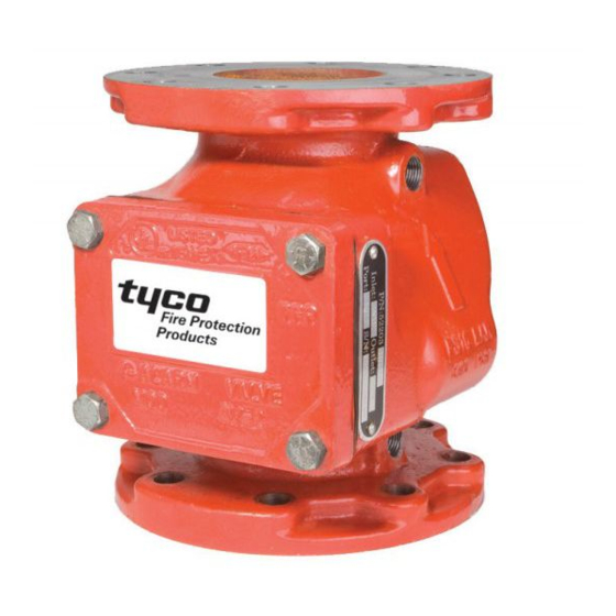
Model AV-1-300 Alarm Check Valve, 300 psi (20,7 bar)
2-1/2, 4, 6, & 8 Inch (DN65, DN100, DN150 & DN200)
Vertical or Horizontal* Installation
General
Description
The Tyco
®
Model AV-1-300 Alarm
Check Valves are divided seat ring,
rubber-faced clapper, waterflow alarm
check valves that are intended for use
in wet pipe (automatic sprinkler) fire
protection systems. They may be in-
stalled vertically or horizontally*, and
they are designed to automatically ac-
tuate electric and/or hydraulic alarms
when there is a steady flow of wa-
ter into the system that is equivalent
to the discharge rate of one or more
sprinklers.
A separately ordered Model RC-1 Re-
tard Chamber (TFP920) is required for
Installations subject to variable pres-
sures. It is used to help prevent false
alarms associated with pressure vari-
ations in public water supplies.
The AV-1-300 Alarm Check Valve Trim
includes pressure gauges to moni-
tor system pressure conditions, a by-
pass check valve, a main drain valve,
and an alarm test valve. The bypass
check valve reduces the pos sibility of
False Alarms by permitting slow as well
as small transient in creases in water
supply pressure to be passed through
to the system without opening the wa-
terway clapper.
NOTICE
The Model AV-1-300 Alarm Check
Valves described herein must be in-
stalled and maintained in compliance
with this document, as well as with the
applicable standards of the National
Fire Protection Association, in addi-
tion to the standards of any authori-
ties having jurisdiction. Failure to do
so may impair the integrity of these
devices.
The owner is responsible for maintain-
ing their fire protection system and
de vices in proper operating condition.
The installing contractor or manufac-
turer should be contacted relative to
any questions.
Page 1 of 22
Nominal
Valve Size
Groove x Groove
2-1/2 Inch
22 lbs.
(DN65)
(10,0 Kg)
4 Inch
45 lbs.
(DN100)
(20,4 Kg)
6 Inch
68 lbs.
(DN150
(30,9 Kg)
8 Inch
129 lbs.
(DN200)
(58,6 Kg)
* 4, 6, and 8 Inch (DN100, DN150, and DN200) Valve Sizes
OCTOBER 2009
End Connections Available
Inlet x Outlet
Flange x Groove
28 lbs.
(12,7 Kg)
51 lbs.
(23,1 Kg)
78 lbs.
(35,4 Kg)
148 lbs.
(67,1 Kg)
Flange x Flange
N/A
62 lbs.
(28,1 Kg)
93 lbs.
(42,2 Kg)
167 lbs.
(75,8 Kg)
TFP910
Advertisement
Table of Contents

Related Manuals for Tyco AV-1-300


Summary of Contents for Tyco AV-1-300
- Page 1 Technical Services: Tel: (800) 381-9312 / Fax: (800) 791-5500 Email: techserv@tycofp.com Model AV-1-300 Alarm Check Valve, 300 psi (20,7 bar) 2-1/2, 4, 6, & 8 Inch (DN65, DN100, DN150 & DN200) Vertical or Horizontal* Installation General Description The Tyco ®...
- Page 2 8 Inch (DN100. DN150, and DN200) Valves with ISO threaded ports have a DN50 inch main drain connection. FIGURE 1 2-1/2, 4, 6 & 8 INCH (DN65, DN100, DN150 & DN200) MODEL AV-1-300 ALARM CHECK VALVE — ASSEMBLY —...
- Page 3 C=120, is as follows 14 feet of 2-1/2 inch Sch. 40 pipe for the 2-1/2 inch AV-1-300 Valve calculated on a typical flow rate of 250 GPM. 23 feet of 4 inch Sch. 40 pipe for the 4 inch AV-1-300 Valve calculated on a typical flow rate of 600 GPM.
-
Page 4: Technical Data
Valves with NPT threaded ports will readily accept the trim arrangements 2-1/2, 4, 6 & 8 INCH (DN65, DN100, DN150 & DN200) detailed in Figures 4 through 6. MODEL AV-1-300 ALARM CHECK VALVE — OPERATION — Operation When the fire protection system is in-... - Page 5 Proper operation of the Tyco ® Mod- Model AV-1-300 Alarm Check Valves, el AV-1-300 Alarm Check Valves de- consideration must be given to the pends upon the trim described in this disposal of the large quantities of wa- data sheet installed in accordance ter that may be associated with drain- with the following instructions.
- Page 6 GROOVE x GROOVE (NORMALLY SHOWN RESTRICTION CLOSED) ASSEMBLY, SEE FIGURE 3 1-1/4 INCH NPT CONNECTION TO DRAIN FIGURE 4 — PART 1 OF 3 VERTICAL CLOSED DRAIN TRIM — STANDARD ORDER —FOR 2-1/2 INCH (DN65) MODEL AV-1-300 ALARM CHECK VALVES (52-204-2-050)—...
- Page 7 FLANGE x FLANGE (NORMALLY SHOWN CLOSED) 2 INCH NPT CONNECTION TO DRAIN FIGURE 4 — PART 2 OF 3 VERTICAL CLOSED DRAIN TRIM — STANDARD ORDER — SEMI-PREASSEMBLED —FOR 4 & 6 INCH (DN100 & DN150) MODEL AV-1-300 ALARM CHECK VALVES (52-204-2-951)—...
- Page 8 SEE FIGURE 3 8 INCH (DN200) FLANGE x GROOVE SHOWN 2 INCH NPT CONNECTION TO DRAIN FIGURE 4 — PART 3 OF 3 VERTICAL CLOSED DRAIN TRIM — STANDARD ORDER — SEMI-PREASSEMBLED —FOR 8 INCH (DN200) MODEL AV-1-300 ALARM CHECK VALVES (52-204-2-952)—...
- Page 9 CLOSED) DRIP FUNNEL 1-1/4 INCH NPT 1-1/4 INCH NPT CONNECTION SUPPORT CONNECTION TO DRAIN TO DRAIN FIGURE 5 — PART 1 OF 3 VERTICAL OPEN DRAIN TRIM — SPECIAL ORDER —FOR 2-1/2 INCH (DN65) MODEL AV-1-300 ALARM CHECK VALVES (52-204-2-053)—...
- Page 10 1-1/4 INCH NPT CONNECTION 2 INCH NPT TO DRAIN CONNECTION TO DRAIN FIGURE 5 — PART 2 OF 3 VERTICAL OPEN DRAIN TRIM — SPECIAL ORDER — SEMI-PREASSEMBLED —FOR 4 & 6 INCH (DN100 & DN150) MODEL AV-1-300 ALARM CHECK VALVES (52-204-2-954)—...
- Page 11 SHOWN 2 INCH NPT FUNNEL CONNECTION 1-1/4 INCH NPT TO DRAIN CONNECTION TO DRAIN FIGURE 5 — PART 3 OF 3 VERTICAL OPEN DRAIN TRIM — SPECIAL ORDER — SEMI-PREASSEMBLED —FOR 8 INCH (DN200) MODEL AV-1-300 ALARM CHECK VALVES (52-204-2-955)—...
- Page 12 CLOSED) RESTRICTION ASSEMBLY, SEE FIGURE 3 2 INCH NPT CONNECTION TO DRAIN FIGURE 6 — PART 1 OF 2 HORIZONTAL CLOSED DRAIN TRIM — SPECIAL ORDER —FOR 4 & 6 INCH (DN100 & DN150) MODEL AV-1-300 ALARM CHECK VALVES (52-204-2-057)—...
- Page 13 SUPERVISED DRAIN VALVE SHOWN (NORMALLY N.O. ALARM CLOSED) CONTROL VALVE 2 INCH NPT CONNECTION TO DRAIN FIGURE 6 — PART 2 OF 2 HORIZONTAL CLOSED DRAIN TRIM — SPECIAL ORDER —FOR 8 INCH (DN200) MODEL AV-1-300 ALARM CHECK VALVES (52-204-2-058)—...
- Page 14 10 (254) F x G RC-1 8-7/8 (225) 8-7/8 (225) 12-1/4 (311) 12-1/4 (311) 16-1/2 (419) 3 (75) 3 (75) ELEVATION VIEW FIGURE 7 — PART 1 OF 3 INSTALLATION DIMENSIONS —FOR 2-1/2 INCH (DN65) MODEL AV-1-300 ALARM CHECK VALVES—...
- Page 15 15 (381) 14 (356) 15 (381) 13-3/4 (349) 14-3/4 (375) 13-3/4 (349) 14-3/4 (375) ELEVATION VIEW PLAN VIEW FIGURE 7 — PART 2 OF 3 INSTALLATION DIMENSIONS —FOR 4 & 6 INCH (DN100 & DN150) MODEL AV-1-300 ALARM CHECK VALVES—...
- Page 16 19-1/2 (495) 19-1/2 (495) 16-1/2 (419) 16-1/2 (419) F x F F x G & G x G ELEVATION VIEW PLAN VIEW FIGURE 7 — PART 3 OF 3 INSTALLATION DIMENSIONS —FOR 8 INCH (DN200) MODEL AV-1-300 ALARM CHECK VALVES—...
- Page 17 Mod- Care and having jurisdiction. Verify that the wa- el AV-1-300 Alarm Check Valve or af- ter motor alarm and/or the pressure ter system operation due to a fire. Maintenance...
- Page 18 TFP910 Page 18 of 22 Step 7. Notify all authorities responsi- While holding the Spring down by the NOTICE ble for monitoring the installation that coils, remove the Hinge Pin. Remove For variable pressure systems, loss of the fire protection system has been re- the Spring and Waterway Clapper excess system pressure will increase turned to service.
- Page 19 Limited False Alarms Follow the step below when repeated Warranty false alarms occur in a variable pres- sure system. Products manufactured by Tyco Fire Step 1. Check for and correct the Suppression & Building Products cause of continued leakage out the (TFSBP) are warranted solely to the alarm line drain.
- Page 20 4 or 6 inch* ..P/N 52-204-2-951 part numbers for factory pre-trimmed 8 inch* ....P/N 52-204-2-952 tended for use with the AV-1-300 Valve Model AV-1-300 Valves. *Provided semi-preassembled Trim described in this data sheet.
- Page 21 TFP910 Page 21 of 22 4 Inch Valves with NPT Ports 6 Inch Valves with NPT Ports 8 Inch Valves with NPT Ports ISO (PN16) Flange x ANSI Flange x ISO (PN10) Flange x 4.50 inch (114,3 mm) 6.50 inch (165,1 mm) 8.62 inch (219,1 mm) Groove O.D .
- Page 22 TFP910 Page 22 of 22 © 2009 TYCO FIRE SUPPRESSION & BUILDING PRODUCTS, 451 North Cannon Avenue, Lansdale, Pennsylvania 19446...
Need help?
Do you have a question about the AV-1-300 and is the answer not in the manual?
Questions and answers