Sign In
Upload
Manuals
Brands
WAGO Manuals
Control Unit
753-647
WAGO 753-647 Manuals
Manuals and User Guides for WAGO 753-647. We have
2
WAGO 753-647 manuals available for free PDF download: Manual
WAGO 753-647 Manual (76 pages)
Brand:
WAGO
| Category:
I/O Systems
| Size: 3.82 MB
Table of Contents
Table of Contents
3
1 Notes about this Documentation
6
Validity of this Documentation
6
Revision History
6
Table 1: Revision History
6
Copyright
7
Symbols
8
Number Notation
10
Font Conventions
10
Table 2: Number Notation
10
Table 3: Font Conventions
10
2 Important Notes
11
Legal Bases
11
Subject to Changes
11
Personnel Qualifications
11
Use of the 750 Series in Compliance with Underlying Provisions
11
Technical Condition of Specified Devices
12
Disposal
12
2.1.4.1.1 Electrical and Electronic Equipment
12
2.1.4.1.2 Packaging
13
Safety Advice (Precautions)
14
Requirements
17
Table 4: Required Hardware of the WAGO I/O SYSTEM
17
Compatibility List
18
Table 5: Controller Compatibility List
18
3 Device Description
19
Device-Specific Safety Information
19
Abbreviations and Terms
20
Table 6: Abbreviations and Terms Used in this Manual
20
General Description
21
Figure 1: Overview of DALI Network with a WAGO I/O SYSTEM 750
21
View
24
Figure 2: View
24
Table 7: Legend for Figure "View
24
Connectors
25
Data Contacts/Local Bus
25
Figure 3: Data Contacts
25
Power Jumper Contacts/Field Supply
26
CAGE CLAMP ® Connectors
26
Figure 4: CAGE CLAMP ® Connectors
26
Table 8: Legend for Figure "CAGE CLAMP ® Connectors
26
Display Elements
28
Operating Elements
28
Figure 5: Display Elements
28
Table 9: Legend for Figure "Display Elements
28
Schematic Diagram
29
Figure 6: Schematic Diagram
29
Technical Data
30
Device
30
Supply
30
Communication
30
Table 10: Technical Data - Device
30
Table 11: Technical Data - Supply
30
Table 12: Technical Data - Communication
30
Connection Type
31
Climatic Environmental Conditions
31
Table 13: Technical Data - Field Wiring
31
Table 14: Technical Data - Data Contacts
31
Table 15: Technical Data - Climatic Environmental Conditions
31
Approvals
32
Standards and Guidelines
33
4 Process Image
34
Watchdog
34
Dedicated IEC Application
35
Full Mode
35
Easy Mode
36
Latching Relay Function
36
DIM in 1- and 2-Button Mode
36
Process Image Overview in the "Easy Mode
37
Table 16: Lighting Control Via Buttons
37
Table 17: Overview of the Output Process Image in the "Easy Mode
37
Table 18: Overview of Input Process Image in the "Easy Mode
37
Activating/De-Activating 64 DALI Actuators, Dimming
38
Table 19: Output and Input Process Image of the DALI Multi-Master Module
38
Table 20: Output and Input Process Image of the DALI Multi-Master Module
39
Activating/De-Activating 16 Groups, Dimming
40
Activating/De-Activating 16 Scenes
40
Table 21: Output and Input PI for the DALI Multi-Master Module in the "Easy Mode" - Byte 18
40
Table 22: Output and Input PI for the DALI Multi-Master Module in the "Easy
40
5 Mounting
41
Mounting Sequence
41
Inserting and Removing Devices
42
Inserting the I/O Module
42
Figure 7: Insert I/O Module (Example)
42
Figure 8: Snap the I/O Module into Place (Example)
42
Removing the I/O Module
43
I/O Modules with Pluggable Wiring Level (Series 753)
43
Figure 9: Removing the I/O Module (Example)
43
Figure 10: Plug and I/O Module
43
Coding
44
Figure 11: Assignment of I/O Module to Plug Using Mini-WSB Tags
44
Figure 12: Attachment of Cable Binders
44
Figure 13: Assembling the Coding Fingers
44
Figure 14: Inserting the Coding Fingers
45
Figure 15: Plugging the Plug into Place
45
Figure 16: "Sure Match" Coding Fingers
45
Plug Removal
46
Figure 17: Pulling the Pull Tab
46
Figure 18: Removing the Plug Without Tools
46
Figure 19: Removing the Plug Using a Screwdriver
46
6 Connect Devices
47
Connecting a Conductor to the CAGE CLAMP
47
Figure 20: Connecting a Conductor to a CAGE CLAMP
47
Power Supply for Marine Applications
48
Power Supply Concept (Marine Applications) with DC/DC Converter - Class a
48
Figure 21: Power Supply Concept (Marine Applications) with DC/DC Converter
48
Table 23: Legend for Figure "Power Supply Concept (Marine Applications) with DC/DC Converter (753-620) - Class a
49
Power Supply Concept (Marine Applications) with AC/DC Power Supply Unit - Class a
50
Figure 22: Power Supply Concept (Marine Applications) with AC/DC Power
50
Table 24: Legend for Figure "Power Supply Concept (Marine Applications) with AC/DC Power Supply Unit (787-1007) - Class a
50
Power Supply Concept (Marine Applications) - Class B
51
Figure 23: Power Supply Concept (Marine Applications) - Class B
51
Table 25: Legend for Figure "Power Supply Concept (Marine Applications)
51
Installation Notes
52
Module Assembly
52
Module Supply
52
Power Supply Configuration for 753-620
54
Figure 24: Configuration Diagram for the DALI Multi-Master DC/DC Converter
54
Figure 25: Configuration Diagram for 3 DALI Multi-Master DC/DC Converters (753-620) with 3 DALI Multi-Master Modules
54
Power Supply Configuration for 787-1007
55
DALI Bus Line
55
Figure 26: Configuration Diagram for a 787-1007 Power Supply with 5 DALI
55
Table 26: Conductor Cross Section Depending on the Cable Length
55
DALI Bus Topology
56
Figure 27: Example of DALI Topology
56
DALI-1 Compatibility
57
7 Commissioning
58
Preparation
58
Table 27: Example of a Fieldbus Node Setup
58
Accessing the DALI Multi-Master Module
59
Module Configuration Notes
59
Construction Site Function" for Initial Startup
59
Notes on Data Management
60
Notes on RESET Commands
60
Configuration of the DALI Network Using the WAGO DALI Configurator
60
8 Diagnostics
62
LED "A" Status Diagnosis
62
Table 28: LED "A" Status Diagnosis
62
LED "B" Status Diagnosis
63
LED "C" Status Diagnosis
63
Table 29: LED "B" Status Diagnosis
63
Table 30: LED "C" Status Diagnosis
63
LED "D" Status Diagnosis
64
LED "E" Status Diagnosis
64
Table 31: LED "D" Status Diagnosis
64
Table 32: LED "E" Status Diagnosis
64
LED "F" Status Diagnosis
65
LED "G" Status Diagnosis
65
Table 33: LED "F" Status Diagnosis
65
Table 34: LED "G" Status Diagnosis
65
LED "H" Status Diagnosis
66
Leds A-H Flashing Together
66
Table 35: LED "H" Status Diagnosis
66
9 Appendix
67
Device Types
67
Table 36: DALI Device Types
67
Table 37: DALI Device Types as of DALI-2
68
Glossary
70
List of Figures
74
List of Tables
75
Advertisement
WAGO 753-647 Manual (74 pages)
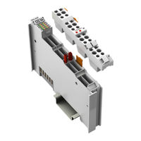
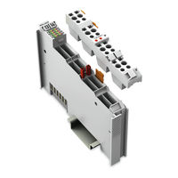
DALI Multi-Master Module for WAGO-I/O-SYSTEM 750
Brand:
WAGO
| Category:
Control Unit
| Size: 1.58 MB
Table of Contents
English
3
Table of Contents
3
1 Notes about this Documentation
5
Validity of this Documentation
5
Copyright
5
Symbols
6
Number Notation
8
Font Conventions
8
2 Important Notes
9
Legal Bases
9
Subject to Changes
9
Personnel Qualifications
9
Use of the 750 Series in Compliance with Underlying Provisions
9
Technical Condition of Specified Devices
10
Safety Advice (Precautions)
11
Requirements
13
PC Hardware
13
PC Software
13
Wago-I/O-System
14
3 Device Description
15
Device-Specific Safety Information
15
Abbreviations and Terms
16
General Description
17
View
20
Table 1: Legend for „View" Figure
20
Connectors
21
Data Contacts/Internal Bus
21
Power Contacts/Field Supply
22
CAGE CLAMP ® Connections
22
Display Elements
23
Operating Elements
24
Schematic Diagram
25
Technical Data
26
Device Data
26
Supply
26
Communication
26
Approvals
27
Standards and Guidelines
27
4 Process Image
28
Dedicated IEC Application
28
Full Mode
29
Easy Mode
29
Latching Relay Function
30
DIM in 1- and 2-Button Mode
30
Process Image Overview in the "Easy" Mode
30
Activating/De-Activating 64 DALI Actuators, Dimming
31
Activating/De-Activating 16 Groups, Dimming
36
Activating/De-Activating 16 Scenes
36
5 Assembly
37
Assembly Sequence
37
Inserting and Removing Devices
38
Inserting I/O Module
38
Removing the I/O Module
39
I/O Modules with Pluggable Wiring Level (Series 753)
40
Coding
41
Connector Removal
43
6 Connect Devices
44
Connecting a Conductor to the CAGE CLAMP
44
Installation Notes
45
Module Assembly
45
Module Supply
45
Power Supply Configuration for 753-620
46
Power Supply Configuration for 787-1007
47
DALI Bus Line
47
DALI Bus Topology
48
7 Commissioning
49
Preparation
49
Accessing the DALI-Multi-Master Module
50
Module Configuration Notes
50
Data Management Notes
51
Configuring the DALI Network Using the WAGO-DALI Configurator (Basic Procedure)
51
8 Diagnostics
53
9 Use in Hazardous Environments
55
Marking Configuration Examples
56
Marking for Europe According to CENELEC and IEC
56
Marking for America According to NEC 500
59
Installation Regulations
60
Special Conditions for Safe Operation of the ATEX and IEC Ex (Acc. DEMKO 08 ATEX 142851X and Iecex PTB 07.0064)
61
Special Conditions for Safe Use (ATEX Certificate TÜV 07 ATEX 554086 X)
62
Special Conditions for Safe Use (IEC-Ex Certificate TUN 09.0001
64
Ansi/Isa 12.12.01
66
10 Glossary
68
11 Appendix
71
List of Figures
72
Deutsch
73
Table 1: Font Conventions
8
Table 1: Number Notation
8
Table 1: Required PC Software
13
Table 1: Requirements PC Hardware
13
Table 4: Optional PC Software
13
Table 2: Required Hardware of the WAGO-I/O-SYSTEM
14
Table 1: Abbreviations and Terms Used in this Manual
16
Table 1: Connections
22
Table 1: Display Elements
23
Table 1: Technical Data - Device
26
Table 2: Technical Data - Supply
26
Table 3: Technical Data - Communication
26
Table 3: Control of Lighting Via Buttons
30
Table 4: Overview of the Output Process Image in the "Easy" Mode
30
Table 5: Overview of Input Process Image in the "Easy" Mode
30
Table 6: Output and Input Process Image for the DALI-Multi-Master Module in the "Easy" Mode
31
Table 1: Conductor Cross Section Depending on the Cable Length
47
Table 7: Example of a Fieldbus Node Setup
49
Table 8: Diagnostics - Status Display for the DALI Network in the WAGO-DALI Configurator and Solutions
54
Table 1: Description of Marking Example for ATEX and IEC Ex Approved I/O Modules According to CENELEC and IEC
56
Table 1: Description of Marking Example for Ex I and IEC Ex I Approved I/O Modules According to CENELEC and IEC
58
Table 1: Description of Marking Example for I/O Modules According to NEC 500
59
Table 1: VDE Installation Regulations in Germany
60
Table 2: Installation Regulations in USA and Canada
60
Table 2: Digital Addressable Lighting Interface - Product Family Standard IEC 62386 (Sept. 2010)
71
List of Tables
73
Advertisement
Related Products
WAGO 753-668/000-004
WAGO 753-646
WAGO 753-514
WAGO 753-1630
WAGO 753-466
WAGO 753-513
WAGO 753-513/000-001
WAGO 750-1504
WAGO 750-508/040-000
WAGO 750-506/000-800
WAGO Categories
I/O Systems
Control Unit
Power Supply
Switch
Controller
More WAGO Manuals
Login
Sign In
OR
Sign in with Facebook
Sign in with Google
Upload manual
Upload from disk
Upload from URL