
Subscribe to Our Youtube Channel
Related Manuals for WAGO 750 Series


Summary of Contents for WAGO 750 Series
- Page 1 Manual WAGO-I/O-SYSTEM 750 750-471 4AI U/I Diff Galv 4-Channel Analog Input; for Voltage/Current Version 1.0.0...
- Page 2 We wish to point out that the software and hardware terms as well as the trademarks of companies used and/or mentioned in the present manual are generally protected by trademark or patent. WAGO is a registered trademark of WAGO Verwaltungsgesellschaft mbH. Manual Version 1.0.0...
-
Page 3: Table Of Contents
Legal Bases ..................11 2.1.1 Subject to Changes ................11 2.1.2 Personnel Qualifications ..............11 2.1.3 Use of the WAGO-I/O-SYSTEM 750 in Compliance with Underlying Provisions ..................11 2.1.4 Technical Condition of Specified Devices......... 12 2.1.4.1 Disposal ..................12 Safety Advice (Precautions) ..............13 Device Description .................. - Page 4 Connect Devices ..................47 ® Connecting a Conductor to the CAGE CLAMP ........47 Connection Examples ................48 Commissioning ..................49 Parameterization with WAGO-I/O-CHECK ..........49 7.1.1 Parameterization Dialog ..............51 7.1.2 Toolbar on the Configuration Dialog ..........52 7.1.3 Navigation area ................
-
Page 5: Notes About This Documentation
Consider power layout of the WAGO-I/O-SYSTEM 750! In addition to these operating instructions, you will also need the manual for the used fieldbus coupler/controller, which can be downloaded at www.wago.com. There, you can obtain important information including information on electrical isolation, system power and supply specifications. - Page 6 Notes about this Documentation WAGO-I/O-SYSTEM 750 750-471 4AI U/I Diff Galv CONTRIBUTORS BE LIABLE FOR ANY DIRECT, INDIRECT, INCIDENTAL, SPECIAL, EXEMPLARY, OR CONSEQUENTIAL DAMAGES (INCLUDING, BUT NOT LIMITED TO, PROCUREMENT OF SUBSTITUTE GOODS OR SERVICES; LOSS OF USE, DATA, OR PROFITS; OR BUSINESS INTERRUPTION)
-
Page 7: Copyright
Manual by third parties that violate pertinent copyright provisions is prohibited. Reproduction, translation, electronic and phototechnical filing/archiving (e.g., photocopying) as well as any amendments require the written consent of WAGO Kontakttechnik GmbH & Co. KG, Minden, Germany. Non-observance will involve the right to assert damage claims. Manual... -
Page 8: Symbols
Notes about this Documentation WAGO-I/O-SYSTEM 750 750-471 4AI U/I Diff Galv Symbols Personal Injury! Indicates a high-risk, imminently hazardous situation which, if not avoided, will result in death or serious injury. Personal Injury Caused by Electric Current! Indicates a high-risk, imminently hazardous situation which, if not avoided, will result in death or serious injury. - Page 9 WAGO-I/O-SYSTEM 750 Notes about this Documentation 750-471 4AI U/I Diff Galv Additional Information: Refers to additional information which is not an integral part of this documentation (e.g., the Internet). Manual Version 1.0.0...
-
Page 10: Number Notation
Font Conventions Table 2: Font Conventions Font Type Indicates italic Names of paths and data files are marked in italic-type. e.g.: C:\Program Files\WAGO Software Menu Menu items are marked in bold letters. e.g.: Save > A greater-than sign between two names means the selection of a menu item from a menu. -
Page 11: Important Notes
2.1.1 Subject to Changes WAGO Kontakttechnik GmbH & Co. KG reserves the right to provide for any alterations or modifications. WAGO Kontakttechnik GmbH & Co. KG owns all rights arising from the granting of patents or from the legal protection of utility patents. -
Page 12: Technical Condition Of Specified Devices
These modules contain no parts that can be serviced or repaired by the user. The following actions will result in the exclusion of liability on the part of WAGO Kontakttechnik GmbH & Co. KG: •... -
Page 13: Safety Advice (Precautions)
Install the device only in appropriate housings, cabinets or in electrical operation rooms! The WAGO-I/O-SYSTEM 750 and its components are an open system. As such, install the system and its components exclusively in appropriate housings, cabinets or in electrical operation rooms. Allow access to such equipment and fixtures to authorized, qualified staff only by means of specific keys or tools. - Page 14 Important Notes WAGO-I/O-SYSTEM 750 750-471 4AI U/I Diff Galv Clean only with permitted materials! Clean housing and soiled contacts with propanol. Do not use any contact spray! Do not use any contact spray. The spray may impair contact area functionality in connection with contamination.
-
Page 15: Device Description
Power to the internal electronics is supplied via internal data bus. The 750-471 module can be used with the fieldbus couplers and controllers of the WAGO-I/O-SYSTEM 750 of the specified version or higher listed in the “Compatibility list” table. Manual... -
Page 16: Table 3: Compatibility List 750-471
Device Description WAGO-I/O-SYSTEM 750 750-471 4AI U/I Diff Galv Table 3: Compatibility List 750-471 Fieldbus Couplers/ Revision Status Bus System Item No. Controllers Firmware 750-375 PROFINET Fieldbus coupler 750-377 Fieldbus coupler 750-333 PROFIBUS Controller 750-833 750-341 Fieldbus coupler 750-342 750-352... - Page 17 WAGO-I/O-SYSTEM 750 Device Description 750-471 4AI U/I Diff Galv Table 3: Compatibility List 750-471 Fieldbus Couplers/ Revision Status Bus System Item No. Controllers Firmware 750-849 Controller 750-889 758-870/000-11x 758-874/000-11x Various I/O IPC 758-875/000-11x 758-876/000-11x Other fieldbus couplers/controllers on request! Manual...
-
Page 18: View
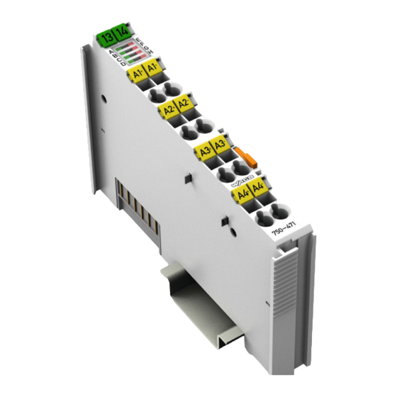
Device Description WAGO-I/O-SYSTEM 750 750-471 4AI U/I Diff Galv View Figure 1: View Table 4: Legend for Figure “View” Pos. Description Details See Section Marking possibility with Mini- Status LEDs “Device Description” > “Display Elements” Data contacts “Device Description” > “Connectors”... -
Page 19: Connectors
WAGO-I/O-SYSTEM 750 Device Description 750-471 4AI U/I Diff Galv Connectors 3.2.1 Data Contacts/Local Bus Communication between the fieldbus coupler/controller and the I/O modules as well as the system supply of the I/O modules is carried out via the local bus. It is comprised of 6 data contacts, which are available as self-cleaning gold spring contacts. -
Page 20: Power Jumper Contacts/Field Supply
Device Description WAGO-I/O-SYSTEM 750 750-471 4AI U/I Diff Galv 3.2.2 Power Jumper Contacts/Field Supply Risk of injury due to sharp-edged blade contacts! The blade contacts are sharp-edged. Handle the I/O module carefully to prevent injury. The I/O module 750-471 has 2 self-cleaning power jumper contacts that supply and transmit power for the field side. - Page 21 WAGO-I/O-SYSTEM 750 Device Description 750-471 4AI U/I Diff Galv Use supply modules for ground (earth)! The I/O module has no power jumper contacts for receiving and transmitting the earth potential. Use a supply module when an earth potential is needed for the subsequent I/O modules.
-
Page 22: Cage Clamp
I/O module can be achieved even in the presence of interference acting on the signal cable. Shield Connection System for Electromagnetic Compatibility! The WAGO Shield Connection System offers a full range of accessories for maintaining electromagnetic compatibility (EMC)! Related information is available at www.wago.com. -
Page 23: Display Elements
WAGO-I/O-SYSTEM 750 Device Description 750-471 4AI U/I Diff Galv Display Elements Figure 5: Display Elements Table 7: Legend for Figure “Display Elements“ Channel Designation LED State Function Operational readiness and trouble-free Green local bus communication Status AI1 No operational readiness or the local... - Page 24 Device Description WAGO-I/O-SYSTEM 750 750-471 4AI U/I Diff Galv Table 7: Legend for Figure “Display Elements“ Channel Designation LED State Function Operational readiness and trouble-free Green local bus communication Status AI4 No operational readiness or the local bus communication is interrupted or...
-
Page 25: Schematic Diagram
WAGO-I/O-SYSTEM 750 Device Description 750-471 4AI U/I Diff Galv Schematic Diagram Figure 6: Schematic Diagram Figure 7: Circuit Diagram Manual Version 1.0.0... -
Page 26: Technical Data
Device Description WAGO-I/O-SYSTEM 750 750-471 4AI U/I Diff Galv Technical Data 3.5.1 Device Data Table 8: Technical Data ‒ Device Width 12 mm Height (from upper edge of 35 DIN rail) 64 mm Depth 100 mm Weight Approx. 50 g 3.5.2... -
Page 27: Inputs
WAGO-I/O-SYSTEM 750 Device Description 750-471 4AI U/I Diff Galv 3.5.5 Inputs Table 12: Technical Data ‒ Inputs Number of inputs 4 (electrically isolated) Signal type Voltage and currents Signal characteristics Differentially Measuring range 0 … 20 mA; 4 … 20 mA 3,6 …... -
Page 28: Climatic Environmental Conditions
Device Description WAGO-I/O-SYSTEM 750 750-471 4AI U/I Diff Galv 3.5.7 Climatic Environmental Conditions Table 16: Technical Data – Climatic Environmental Conditions Surrounding air temperature, operation 0 °C … 55 °C Surrounding air temperature, storage −25 °C … +85 °C Relative humidity without condensation Max. 95 %... -
Page 29: Approvals
[Temperature: B, Humidity B, Vibration: B, EMC: B, Enclosure: A] More information about approvals. Detailed references to the approvals are listed in the document “Overview Approvals WAGO-I/O-SYSTEM 750”, which you can find via the internet under: www.wago.com > SERVICES > DOWNLOADS > Additional documentation and information on automation products >... -
Page 30: Standards And Guidelines
Device Description WAGO-I/O-SYSTEM 750 750-471 4AI U/I Diff Galv Standards and Guidelines The I/O modules 750-471 meet the following requirements on emission and immunity of interference: EU EMC Directive 2014/30/EU EMC CE-Immunity to interference EN 61000-6-2 EMC CE-Emission of interference... -
Page 31: Process Image
1; B2 is not used. The measured value is then mapped with a resolution of thirteen bits on bits B3 ... B15. The WAGO-I/O-CHECK commissioning tool can be used to parameterize the required operating mode. Alternatively, the I/O module can also be parameterized via PROFIBUS and PROFINET device description (GSD file). -
Page 32: Table 17: Process Image - I/O Module750-471
Process Image WAGO-I/O-SYSTEM 750 750-471 4AI U/I Diff Galv Table 17: Process Image – I/O module750-471 Process image Input Output Byte 0 Status byte CH1_S0 Byte 0 Control byte CH1_C0 Byte 1 Depending on status byte: Byte 1 Depending on control byte:... -
Page 33: Status Bytes
WAGO-I/O-SYSTEM 750 Process Image 750-471 4AI U/I Diff Galv Status bytes Status bytes are identically implemented for all channels. Therefore, the following description in this section applies to all status bytes of the I/O module. Table 18: Status byte CH1_S0... -
Page 34: Process Data
Process Image WAGO-I/O-SYSTEM 750 750-471 4AI U/I Diff Galv Process Data 4.3.1 Overview of Sensor Types The following table serves as an overview of all supported sensor types. The following sections provide detailed information about the individual sensor types. The signal types “0 to 10 V,” “0 to 20 mA,” “4 to 20 mA” and types “±10 V,” “±200 mV,”... -
Page 35: Table 20: Signal Types "0
WAGO-I/O-SYSTEM 750 Process Image 750-471 4AI U/I Diff Galv 4.3.1.1 Signal Types “0 … 10 V”, “0 … 20 mA” and “4 … 20 mA” (Default) Only one signal type per channel can be set as operating mode via the commissioning tool. -
Page 36: Table 21: Signal Types "0
Process Image WAGO-I/O-SYSTEM 750 750-471 4AI U/I Diff Galv Table 21: Signal Types “0 … 10 V, 0 … 20 mA” and “4 … 20 mA” with Status Information in the Process Image Measuring range Process value Status Error byte Binary 0 …... -
Page 37: Signal Types "± 10 V", "± 200 Mv" "± 20 Ma", Two's Complement (Default)
WAGO-I/O-SYSTEM 750 Process Image 750-471 4AI U/I Diff Galv 4.3.1.2 Signal Types “± 10 V”, “± 200 mV” “± 20 mA”, Two’s complement (Default) Only one signal type per channel can be set as operating mode via the commissioning tool. -
Page 38: Table 23: Signal Types "± 10 V", "± 200 Mv" "± 20 Ma", Two's Complement With
Process Image WAGO-I/O-SYSTEM 750 750-471 4AI U/I Diff Galv Table 23: Signal Types “± 10 V”, “± 200 mV” “± 20 mA”, Two’s Complement with Status Information in the Process Image Measuring range Process value Status Error byte Binary Hex. -
Page 39: Table 25: Signal Types "± 10 V", "± 200 Mv" "± 20 Ma", Amount/Sign Format With
WAGO-I/O-SYSTEM 750 Process Image 750-471 4AI U/I Diff Galv Table 25: Signal Types “± 10 V”, “± 200 mV” “± 20 mA”, Amount/sign format with Status Information in the Process Image Measuring range Process value Status Error byte Binary Hex. -
Page 40: Signal Type "Namur Ne43
Process Image WAGO-I/O-SYSTEM 750 750-471 4AI U/I Diff Galv 4.3.1.3 Signal Type “Namur NE43” Table 26: Signal Type “Namur NE43”, Two’s Complement Measuring range [mA] Process value Status Error byte hex. Binary Hex. Dec. Namur NE43 < - 14.0 mA 1111.1110.0111.0011... -
Page 41: Table 27: Signal Type "Namur Ne43", Two's Complement With Status Information
WAGO-I/O-SYSTEM 750 Process Image 750-471 4AI U/I Diff Galv Table 27: Signal Type “Namur NE43”, Two’s Complement with Status Information in the Process Image Measuring range [mA] Process value Status Error Binary byte hex. Hex. Dec. Namur NE43 XFÜ < − 14.0 mA 1111.1110.0111.0... -
Page 42: Table 28: Signal Type "Namur Ne43", Amount/Sign Format
Process Image WAGO-I/O-SYSTEM 750 750-471 4AI U/I Diff Galv Table 28: Signal Type “Namur NE43”, Amount/sign format Measuring range [mA] Process value Statusbyte Error hex. Binary Hex. Dec. Namur NE43 < - 14,0 mA 1000.0001.1000.1100 0x818C − 397 0x50 Neg. sensor overload <... -
Page 43: Table 29: Signal Type "Namur Ne43", Amount/Sign Format With Status
WAGO-I/O-SYSTEM 750 Process Image 750-471 4AI U/I Diff Galv Table 29: Signal Type “Namur NE43”, Amount/sign format with Status Information in the Process Image Measuring range [mA] Process value Statusbyte Error Binary hex. Hex. Dec. Namur NE43 XFÜ < − 14,0 mA 1000.0001.1000.1... -
Page 44: Mounting
Don't forget the bus end module! Always plug a bus end module (750-600) onto the end of the fieldbus node! You must always use a bus end module at all fieldbus nodes with WAGO-I/O- SYSTEM 750 fieldbus couplers/controllers to guarantee proper data transfer. -
Page 45: Inserting And Removing Devices
WAGO-I/O-SYSTEM 750 Mounting 750-471 4AI U/I Diff Galv Inserting and Removing Devices Perform work on devices only if they are de-energized! Working on energized devices can damage them. Therefore, turn off the power supply before working on the devices. 5.2.1... -
Page 46: Removing The I/O Module
Mounting WAGO-I/O-SYSTEM 750 750-471 4AI U/I Diff Galv 5.2.2 Removing the I/O Module Remove the I/O module from the assembly by pulling the release tab. Figure 10: Removing the I/O Module (Example) Electrical connections for data or power jumper contacts are disconnected when removing the I/O module. -
Page 47: Connect Devices
Only one conductor may be connected to each CAGE CLAMP Do not connect more than one conductor at one single connection! If more than one conductor must be routed to one connection, these must be connected in an up-circuit wiring assembly, for example using WAGO feed- through terminals. ®... -
Page 48: Connection Examples
Connect Devices WAGO-I/O-SYSTEM 750 750-471 4AI U/I Diff Galv Connection Examples Figure 12: Connection Example 750-471 Manual Version 1.0.0... -
Page 49: Commissioning
Calibration of channels and adjustment of analog inputs • Monitoring You can obtain the WAGO-I/O-CHECK software on a CD under Item No. 759- 302. This CD contains all the application program files and an explanation. You can find a description at the internet page at http://www.wago.com! -
Page 50: Figure 13: Wago-I/O-Check User Interface
Commissioning WAGO-I/O-SYSTEM 750 750-471 4AI U/I Diff Galv After the node structure has been identified in WAGO-I/O-CHECK, it appears in the overview area. To open specific parameterization dialogs for the I/O module, proceed as follow: Choose the I/O module. Right-click to open the context menu and select the Settings menu item. -
Page 51: Parameterization Dialog
WAGO-I/O-SYSTEM 750 Commissioning 750-471 4AI U/I Diff Galv 7.1.1 Parameterization Dialog Figure 14: Parameterization Dialog 750-471 The parameterization dialog is divided into the following areas: Title Bar with information about the position of the selected I/O module Information area including item number, name as well as version number... -
Page 52: Toolbar On The Configuration Dialog
Table 30: Toolbar Button Function Description Exit Closes the configuration dialog. Opens an existing parameterization file. WAGO- Open I/O-CHECK displays the default dialog for opening files. Saves the current parameter in a parameter file. Save WAGO-I/O-CHECK displays the default dialog for saving files. -
Page 53: Navigation Area
WAGO-I/O-SYSTEM 750 Commissioning 750-471 4AI U/I Diff Galv 7.1.3 Navigation area Module- and channel-specific settings, as well as calibration and scaling settings, can be selected through the navigation bar on the left side of the parameterization dialog window. Figure 16: Navigation Press one of the buttons to display the corresponding parameters. -
Page 54: Common
Commissioning WAGO-I/O-SYSTEM 750 750-471 4AI U/I Diff Galv 7.1.3.1 Common Figure 17: Parameter „Common“ The following I/O parameters can be set through the menu Common: Table 32: "General" Parameters Selection Field Settings Number format There are two ways the process image can be... - Page 55 WAGO-I/O-SYSTEM 750 Commissioning 750-471 4AI U/I Diff Galv No Manufacturer Scaling in Siemens S5 Format! If Siemens S5 format is switched on, the manufacturer scaling setting (see Section “Scaling”) is not taken into account! Manual Version 1.0.0...
-
Page 56: Channel Settings
Commissioning WAGO-I/O-SYSTEM 750 750-471 4AI U/I Diff Galv 7.1.3.2 Channel Settings Figure 18: Parameter „Channel“ In the menus Channel 1 … 4 you can make channel granular settings: Table 33: Parameter „Channel“ Selection Field Possible Settings Signal type The measurement range can be set and the channel switched on or off here. - Page 57 WAGO-I/O-SYSTEM 750 Commissioning 750-471 4AI U/I Diff Galv Table 33: Parameter „Channel“ Selection Field Possible Settings Off* Wire break diagnostics is OFF. Diagnosis: Measuring The measurement overrange diagnostics can be range overflow switched on or off here. Measurement overrange diagnostics is OFF.
-
Page 58: Scaling
Commissioning WAGO-I/O-SYSTEM 750 750-471 4AI U/I Diff Galv 7.1.3.3 Scaling The settings entered in the "Scaling" dialog window directly affect the process value. Scaling is carried out for each channel and is saved permanently, i.e. available after restarting the node. - Page 59 WAGO-I/O-SYSTEM 750 Commissioning 750-471 4AI U/I Diff Galv Table 34: “Scaling” Parameters Selection/Control Field Possible Settings Show values in The hexadecimal representation can be switched on or hexadecimal off. Observe the Detailed information about User Scaling! Detailed information about user scaling can be found in Section “Scaling Measured Values”!
-
Page 60: Calibration
Commissioning WAGO-I/O-SYSTEM 750 750-471 4AI U/I Diff Galv 2/4 Analogei ngangs klemme Analog 750- 464 ( Skali erung) 7.1.3.4 Calibration The I/O module can be recalibrated to correct the effects of long-term drift or to optimize accuracy in a thermally stable state. Calibration is dependent on the signal type for current or voltage measurement previously set for the respective channel. -
Page 61: Figure 20: "Calibration" Parameters
WAGO-I/O-SYSTEM 750 Commissioning 750-471 4AI U/I Diff Galv Figure 20: “Calibration” Parameters Table 35: Calibration Parameters Selection/Control Field Possible settings User calibration When user calibration is switched on, the user can enter values for offset and gain. The values can be represented and edited as decimals or hexadecimals. -
Page 62: Figure 21: Offset Correction
Commissioning WAGO-I/O-SYSTEM 750 750-471 4AI U/I Diff Galv The calibration process is independent of the set signal type! User calibration follows the same principle as the current and voltage measurement. The content of the dialog windows differs accordingly! To select the process value for the respective channel, select the corresponding tab [Channel 1] ... - Page 63 WAGO-I/O-SYSTEM 750 Commissioning 750-471 4AI U/I Diff Galv The I/O module can also be parameterized via PROFIBUS and PROFINET device description (GSD file). The parameterization description can be found in the appendix in Section “Configuration and Parameterization via GSD File with PROFIBUS DP and PROFINET IO.”...
-
Page 64: Scaling Measured Values
Commissioning WAGO-I/O-SYSTEM 750 750-471 4AI U/I Diff Galv </dg_ Scaling Measured Values User scaling serves to adjust the process values. When user scaling is used, the required accuracy of the process value resolution is changed, but not fundamentally limited. User scaling is optional. -
Page 65: Diagnostics
You can activate or deactivate these diagnostics separately in WAGO-I/O-CHECK (see section “Startup” > … > “Parameterization with WAGO-I/O-CHECK”). The I/O module only allows one error to be indicated. A dedicated bit in the status byte is assigned to each error. -
Page 66: Table 38: Behavior In The Event Of An I/O Module Error Dependent On The
Diagnostics WAGO-I/O-SYSTEM 750 750-471 4AI U/I Diff Galv Table 38: Behavior in the Event of an I/O Module Error Dependent on the Configuration Configuration I/O module behavior I/O module behavior Wire break/ / Underrange/ for wire break/ for range violation... - Page 67 WAGO-I/O-SYSTEM 750 Diagnostics 750-471 4AI U/I Diff Galv Note how long diagnostics are displayed! A diagnosed error status is displayed at least 200 ms even if the detected error status is no longer present in this period. If a higher-priority error status occurs in this period, the higher-priority error status is displayed for 200 ms and the lower- priority error status is lost.
-
Page 68: Firmware Changes
Firmware Changes You can update firmware on the Series 750 I/O Modules with the software “WAGO I/O-Update 750.” The I/O modules can be updated via the service interface or, for ETHERNET-based fieldbuses, via the fieldbus connection on the fieldbus coupler/controller. -
Page 69: Use In Hazardous Environments
Use in Hazardous Environments 750-471 4AI U/I Diff Galv Use in Hazardous Environments The WAGO-I/O-SYSTEM 750 (electrical equipment) is designed for use in Zone 2 hazardous areas. The following sections include both the general identification of components (devices) and the installation regulations to be observed. The individual subsections of the “Installation Regulations”... -
Page 70: Marking Configuration Examples
Use in Hazardous Environments WAGO-I/O-SYSTEM 750 750-471 4AI U/I Diff Galv Marking Configuration Examples 9.1.1 Marking for Europe According to ATEX and IECEx Figure 23: Marking Example According to ATEX and IECEx Figure 24: Text Detail – Marking Example According to ATEX and IECEx Manual Version 1.0.0... -
Page 71: Table 39: Description Of Marking Example According To Atex And Iecex
WAGO-I/O-SYSTEM 750 Use in Hazardous Environments 750-471 4AI U/I Diff Galv Table 39: Description of Marking Example According to ATEX and IECEx Marking Description TUEV 07 ATEX 554086 X Approving authority resp. certificate numbers IECEx TUN 09.0001 X Dust Equipment group: All except mining... -
Page 72: Figure 25: Marking Example For Approved Ex I I/O Module According To Atex
Use in Hazardous Environments WAGO-I/O-SYSTEM 750 750-471 4AI U/I Diff Galv Figure 25: Marking Example for Approved Ex i I/O Module According to ATEX and IECEx Figure 26: Text Detail – Marking Example for Approved Ex i I/O Module According to ATEX and... -
Page 73: Marking For America (Nec) And Canada (Cec)
WAGO-I/O-SYSTEM 750 Use in Hazardous Environments 750-471 4AI U/I Diff Galv Table 40: Description of Marking Example for Approved Ex i I/O Module According to ATEX and IECEx Marking Description TUEV 12 ATEX 106032 X Approving authority resp. certificate numbers... -
Page 74: Figure 27: Marking Example According To Nec
Use in Hazardous Environments WAGO-I/O-SYSTEM 750 750-471 4AI U/I Diff Galv Figure 27: Marking Example According to NEC Figure 28: Text Detail – Marking Example According to NEC 500 Table 41: Description of Marking Example According to NEC 500 Marking... -
Page 75: Figure 29: Text Detail - Marking Example For Approved Ex I I/O Module
WAGO-I/O-SYSTEM 750 Use in Hazardous Environments 750-471 4AI U/I Diff Galv Figure 29: Text Detail – Marking Example for Approved Ex i I/O Module According to NEC 505 Table 42: Description of Marking Example for Approved Ex i I/O Module According to NEC 505... -
Page 76: Figure 31: Text Detail - Marking Example For Approved Ex I I/O Modules
Use in Hazardous Environments WAGO-I/O-SYSTEM 750 750-471 4AI U/I Diff Galv Figure 31: Text Detail – Marking Example for Approved Ex i I/O Modules According to CEC 18 attachment J Table 44: Description of Marking Example for Approved Ex i I/O Modules According to CEC 18... -
Page 77: Installation Regulations
Special Notes Regarding Explosion Protection The following warning notices are to be posted in the immediately proximity of the WAGO-I/O-SYSTEM 750 (hereinafter “product”): WARNING – DO NOT REMOVE OR REPLACE FUSED WHILE ENERGIZED! WARNING – DO NOT DISCONNECT WHILE ENERGIZED! WARNING –... - Page 78 Use in Hazardous Environments WAGO-I/O-SYSTEM 750 750-471 4AI U/I Diff Galv Explosive atmosphere occurring simultaneously with assembly, installation or repair work must be ruled out. Among other things, these include the following activities • Insertion and removal of components •...
-
Page 79: Special Notes Regarding Ansi/Isa Ex
WAGO-I/O-SYSTEM 750 Use in Hazardous Environments 750-471 4AI U/I Diff Galv 9.2.2 Special Notes Regarding ANSI/ISA Ex For ANSI/ISA Ex acc. to UL File E198726, the following additional requirements apply: • Use in Class I, Division 2, Group A, B, C, D or non-hazardous areas only •... -
Page 80: Appendix
Behavior after Overwriting with WAGO-I/O-CHECK ! If WAGO-I/O-CHECK is used to overwrite a parameterization made with the GSD file, the I/O module operates with the WAGO-I/O-CHECK settings until the 750-333 and 750-833 Fieldbus Couplers/Controllers are restarted. After restart, the I/O module is re-parameterized via PROFIBUS using the GSD settings. -
Page 81: 4Ai U/I Diff/Galv Parameterization
WAGO-I/O-SYSTEM 750 Appendix 750-471 4AI U/I Diff Galv 10.1.2 4AI U/I Diff/Galv Parameterization Except for the user limit values, the GSD file can be used to provide the I/O module on the PROFIBUS DP fieldbus device with all operating parameters. -
Page 82: Figure 33: Example Of The Fieldbus Couplers/Controllers Parameterization Dialog
Appendix WAGO-I/O-SYSTEM 750 750-471 4AI U/I Diff Galv On the PROFINET IO 750 375(/025 000) and 750x377(/025 000) fieldbus couplers, the user limits for the channels can also be set using the GSD file; if they are fallen below or exceeded by the respective input value, a corresponding process alarm is transmitted. -
Page 83: All Profibus Dp And Profinet Io Fieldbus Couplers/Controllers
− 32768 … 0* … 32767 − 32768 … 0* … Offset Offset 32767 − 32768 … 16384* … − 2.0000 … 1.0000* … Gain Gain 32767 1.9999 Default setting The resolution 1/16384 is already taken into account in WAGO-I/O-CHECK. Manual Version 1.0.0... -
Page 84: Profibus Dp Fieldbus Couplers/Controllers 750-333(/0Xx-000), 750-833(/0Xx-000)
Appendix WAGO-I/O-SYSTEM 750 750-471 4AI U/I Diff Galv 10.1.2.2 PROFIBUS DP Fieldbus Couplers/Controllers 750-333(/0xx-000), 750- 833(/0xx-000) The aforementioned fieldbus coupler/ controller allow channel-specific parameterization of behavior at diagnosis. Table 48: General Module/Channel parameters Parameter Value Explanation Diagnosis The fieldbus coupler/controller signals a diagnosis, if Channel x (x = 0…3) - Page 85 WAGO-I/O-SYSTEM 750 Appendix 750-471 4AI U/I Diff Galv Table 49: General Module/Channel parameters Parameters Value Explanation Diagnostics: 0 (false) An overload on the respective signal channel Overload does not lead to transmission of a diagnostic Channel x (x = 0…3) alarm nor entry in the diagnostics database of the station proxy.
- Page 86 Appendix WAGO-I/O-SYSTEM 750 750-471 4AI U/I Diff Galv Table 49: General Module/Channel parameters Parameters Value Explanation User-defined upper limit Based on the value range of the Channel x (x = 0…3) input signal that can lead to the abovementioned event of a process alarm can be specified.
-
Page 87: List Of Figures
® Figure 11: Connecting a Conductor to a CAGE CLAMP ........47 Figure 12: Connection Example 750-471 ............48 Figure 13: WAGO-I/O-CHECK User Interface ............50 Figure 14: Parameterization Dialog 750-471 ............51 Figure 15: Toolbar ....................52 Figure 16: Navigation ..................53 Figure 17: Parameter „Common“ ................54 Figure 18: Parameter „Channel“... -
Page 88: List Of Tables
List of Tables WAGO-I/O-SYSTEM 750 750-471 4AI U/I Diff Galv List of Tables Table 1: Number Notation ..................10 Table 2: Font Conventions .................10 Table 3: Compatibility List 750-471 ..............16 Table 4: Legend for Figure “View” ..............18 Table 5: Legend for Figure “Power Jumper Contacts” ........20 ®... - Page 89 WAGO-I/O-SYSTEM 750 List of Tables 750-471 4AI U/I Diff Galv Table 41: Description of Marking Example According to NEC 500 .....74 Table 42: Description of Marking Example for Approved Ex i I/O Module According to NEC 505 ................75 Table 43: Description of Marking Example for Approved Ex i I/O Modules According to NEC 506 ................75...
- Page 90 WAGO Kontakttechnik GmbH & Co. KG Postfach 2880 • 32385 Minden Hansastraße 27 • 32423 Minden Phone: 0571/887 – 0 Fax: 0571/887 – 169 E-Mail: info@wago.com Internet: http://www.wago.com...
Need help?
Do you have a question about the 750 Series and is the answer not in the manual?
Questions and answers