Table of Contents
Advertisement
Quick Links
DMU318...W
150 ... 1600mm
4...20 mA
10 - 30 V
0...10 V
DC
Function largely independent of surface
properties, ideal for detection of liquids,
bulk materials, transparent media, ...
Sound exit less than 90° to the longitudinal
axis
Small dead zone at long scanning range
1 analog output 0 ... 10V or 4 ... 20mA
1 switching output (PNP or NPN)
NO/NC function reversible
NEW
– Both outputs can easily be taught
using a button
NEW
– Stable plastic design
NEW
– Temperature-compensated
scanning range
IP 67
IEC 60947...
IEC 60947...
Accessories:
(available separately)
Mounting systems
Mounting adapter M18-M30:
BTX-D18M-D30 (Part no. 50125860)
Cables with M12 connector
(KD ...)
Leuze electronic GmbH + Co. KG
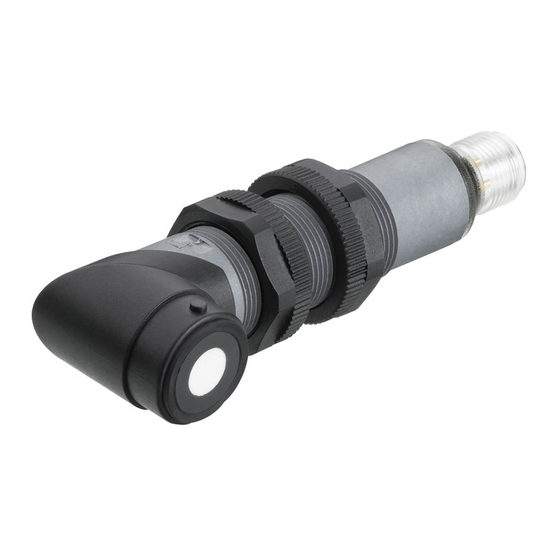
90° angled ultrasonic sensors with analog and switching output
Dimensioned drawing
50 ... 400mm
A
B
C
Electrical connection
In der Braike 1 D-73277 Owen
Active sensor surface
Teach-in button
Indicator diodes
DMU318-400.W...-M12 - 01
DMU318-1600.W...-M12 - 01
Advertisement
Table of Contents

Related Manuals for Leuze electronic DMU318 W Series


Summary of Contents for Leuze electronic DMU318 W Series
- Page 1 IEC 60947... Accessories: (available separately) Mounting systems Mounting adapter M18-M30: BTX-D18M-D30 (Part no. 50125860) Cables with M12 connector (KD …) Leuze electronic GmbH + Co. KG In der Braike 1 D-73277 Owen DMU318-400.W…-M12 - 01 DMU318-1600.W…-M12 - 01...
-
Page 2: Table Of Contents
DMU318…W Technical data Diagrams DMU318-400.W3/…-M12 Ultrasonic specifications DMU318-400.W3/…-M12 DMU318-1600.W3/…-M12 Typ. response behavior (plate 200x200mm) Scanning range 50 … 400mm 150 … 1600mm Adjustment range 50 … 400mm 150 … 1600mm Ultrasonic frequency 300kHz 230kHz Typ. opening angle 8° 8° Resolution <... -
Page 3: Scanning Range 1)
50136109 150 … 1600mm / NPN / voltage output 0 … 10V / teach button / with 90° angled head DMU318-1600.W3/2VK-M12 50136107 Leuze electronic GmbH + Co. KG In der Braike 1 D-73277 Owen DMU318-400.W…-M12 - 01 DMU318-1600.W…-M12 - 01... -
Page 4: Dmu318-400.W3
DMU318…W Device functions and indicators – switching output The sensor has a button for setting switching output OUT1 and analog output Analog OUT. Use the teach button to perform the 1-point teach, the 2-point window-teach and to changeover the switching function (NO contact/NC contact). Device status and switching states for OUT1 are indicated as follows by means of a yellow LED: Switching output OUT1 1-point teach (1 switching point) -
Page 5: Dmu318-1600.W3
LEDs flash at 8Hz until an error-free teach event is performed. 1) See table "Switching behavior with 2-point window-teach as a function of the switching function" Leuze electronic GmbH + Co. KG In der Braike 1 D-73277 Owen DMU318-400.W…-M12 - 01... - Page 6 DMU318…W Adjusting the switching function (NC/NO) via the teach button The switching function of the sensor is preset as follows on delivery: OUT 1: NO contact The output function can be switched from NO contact (NO - normally open) to NC contact (NC - normally closed) and vice versa. If the switching function is changed, the switching output is changed to the opposite state (toggled).
-
Page 7: Object Distance X [Mm]
LED flashing = OUT 1 ready for teaching, blue LED flashing = Analog OUT ready for teaching. Leuze electronic GmbH + Co. KG In der Braike 1 D-73277 Owen DMU318-400.W…-M12 - 01 DMU318-1600.W…-M12 - 01... - Page 8 DMU318…W 1-point teach of the analog output First activate the previously described teach mode for output Analog OUT. By selecting an object distance within the scanning range, the characteristic curve of the analog output can be adjusted. If an object is located outside of the taught measurement range, an error signal is output. A different analog signal is output here by the sensor for the errors "distance too close: object outside of the measurement range"...
- Page 9 Sync/MUX pin 5 on all sensors in the network must be connected to one another. Generation of the synchronization signal for all sensors in the network occurs automatically. Leuze electronic GmbH + Co. KG In der Braike 1 D-73277 Owen DMU318-400.W…-M12 - 01...
- Page 10 DMU318…W Multiplex operation In this operating mode the mutual interference of adjacent sensors can be reliably avoided. For this purpose, up to 4 sensors of the same type are wired together in a network according to the following diagram. The devices operate in multiplex operation with a cyclically time-delayed transmission pulse and are switched to a passive state outside of the active phase, whereby the states of the outputs are frozen until the next active phase.