
Subscribe to Our Youtube Channel
Related Manuals for Leuze electronic DDLS 200


Summary of Contents for Leuze electronic DDLS 200
- Page 1 DDLS 200 Bus-Capable Optical Data Transmission T E C H N I C A L D E S C R I P T I O N...
- Page 2 Leuze electronic GmbH + Co. KG P.O. Box 1111, D- 73277 Owen / Teck Tel. +49(0) 7021/ 573-0, Fax +49(0)7021/ 573-199 Sales and Service Germany Sales Region East Sales Region North Sales Region South Phone 035027/629-106 Phone 07021/573-306 Phone 07021/573-307...
-
Page 3: Table Of Contents
Mounting / Installation (all device models)............ 11 Mounting and alignment..................... 11 Arrangement of adjacent transmission systems ..............12 Cascading (series connection) of several DDLS 200 data paths........14 Electrical connection ......................16 4.4.1 Electrical connection - devices with screwed cable glands and terminals........16 4.4.2... - Page 4 10.4.1 Assignment of the RJ45 and M12 Ethernet cables..............54 10.4.2 Installing cable with RJ45 connector ....................55 10.5 LED Indicators Ethernet..................... 56 10.6 Important notices for system integrators................56 10.6.1 Typical bus configuration ......................57 10.6.2 Timing ............................58 DDLS 200 Leuze electronic...
- Page 5 14.4.5 Contact assignment for M12 Ethernet connection cable KB ET… ..........70 14.4.6 Technical data for M12 Ethernet connection cable KB ET… ............70 14.4.7 Order codes for M12 Ethernet connection cables KB ET… ............71 Leuze electronic DDLS 200...
-
Page 6: General Information
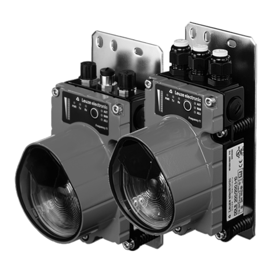
With the DDLS 200 Series, Leuze electronic offers optical, high-performance data transmission sys- tems. The data transmission units are robust and are not subject to wear. A DDLS 200 data transmission system consists of a set of two transmission and reception units: e.g. DDLS 200/200.1-10 and DDLS 200/200.2-10. -
Page 7: Operating Principle
• Minimum transmission times (real-time capable) • Deterministic transmission The DDLS 200 data transmission system, which is available in several model variations, makes pos- sible the contact-free transmission of the following bus protocols: • PROFIBUS FMS, DP, MPI, FMS - DP mixed-operation, up to max. 1.5Mbit/s, PROFISAFE •... -
Page 8: Safety Notices
The optical DDLS 200 data transmission system was developed, manufactured and tested in accor- dance with applicable safety standards. It corresponds to the state of the art. The device series DDLS 200 is "UL LISTED" according to U.S. American and Canadian safety standards, and fulfills the requirements of Underwriter Laboratories Inc. (UL). -
Page 9: Organizational Measures
Mounting, commissioning and maintenance of the device may only be carried out by qualified person- nel. Work on electrical installations may only be carried out by qualified electricians. Repair Repairs must only be carried out by the manufacturer or an authorized representative. Leuze electronic DDLS 200... -
Page 10: Technical Data
800mA with 24VDC (no load at switching output) with optics heating Optical data Sensing distance 0.2 … 30m (DDLS 200/30…) 0.2 … 80m (DDLS 200/80…) 0.2 … 120m (DDLS 200/120…) 0.2 … 200m (DDLS 200/200…) 0.2 … 300m (DDLS 200/300…) 0.2 …... - Page 11 UL 60950 and CSA C22.2 No. 60950 Warning: This is a Class A product. In a domestic environment this product may cause radio interfer- ence, in which case the operator may be required to take adequate measures. Leuze electronic DDLS 200...
-
Page 12: Dimensioned Drawings
DDLS 200 / … - 20 … DDLS 200 / … - 40 … DDLS 200 / … - 50 … DDLS 200 / … - 10 … - M12 DDLS 200 / … - 50 … - M12 Permissible cables: DDLS 200 / …... -
Page 13: Mounting / Installation (All Device Models)
Figure 4.1: Mounting the devices Note The fine alignment of the transmission system is performed during commissioning (see chapter 11.3.2 "Fine adjustment"). The position of the optical axis of the DDLS 200 can be found in chapter 3.2. Leuze electronic... -
Page 14: Arrangement Of Adjacent Transmission Systems
Mounting / Installation (all device models) Arrangement of adjacent transmission systems To prevent mutual interference of adjacent transmission systems, the following measures should be taken in addition to exact alignment: DDLS 200/XXX. DDLS 200/XXX. ( frequency f ( frequency f Frequency-offset arrangement! DDLS 200/XXX. - Page 15 • In the case of identical frequency arrangement, the distance between two parallel data trans- mission paths must be at least • 400mm + tan (1.5°) • operating range (DDLS 200/30…) • 300mm + tan (1.0°) • operating range (DDLS 200/80…) •...
-
Page 16: Cascading (Series Connection) Of Several Ddls 200 Data Paths
Mounting / Installation (all device models) Cascading (series connection) of several DDLS 200 data paths If two communicating participants (TN) are separated by several optical transmission paths between two participants, then this is called cascading. There are further participants between the individual optical transmission paths in this case. - Page 17 Note The individual time delay of the optical transmission path is specified in the chapters of the individual bus systems and depends on the type, switch position, and transmission rate. Leuze electronic DDLS 200...
-
Page 18: Electrical Connection
Before connecting the device, be sure that the supply voltage agrees with the value printed on the nameplate. The DDLS 200… is designed in accordance with safety class III for supply by PELV (Pro- tective Extra Low Voltage, with reliable disconnection). - Page 19 M16 x 1.5 screwed cable gland and guide the continu- ing supply voltage cable through this gland. The housing seal is, in this way, ensured (Pro- tection Class IP 65). The housing top can be removed and replaced while under voltage. Leuze electronic DDLS 200...
- Page 20 Switch S1 is also present on the device models with M12 connectors. Switching output The DDLS 200 is equipped with a switching output OUT WARN which is activated if the receiving level in the receiver drops. Output voltage: 0 …...
-
Page 21: Electrical Connection - Devices With M12 Connectors
Switching input for transmitter/receiver cut-off: 0 … 2 V DC: transmitter/receiver switched off, no transmission 18 … 30 V DC: transmitter/receiver active, normal function M12 plug (A-coded) Functional earth Thread Functional earth (housing) Figure 4.7: Assignment M12 connector PWR IN Leuze electronic DDLS 200... - Page 22 4.7). Switching input The DDLS 200 is equipped with a switching input IN (pin 1), via which the transmitter/receiver unit can be switched off, i.e. no infrared light is transmitted and at the bus terminals the corresponding bus bias level is present / the bus driver is high resistance.
-
Page 23: Profibus / Rs 485
• 6 baud rates configurable (see chapter 5.3) • Optional M12 connector set for conversion available as accessory • It is possible to cascade several DDLS 200 (see chapter 4.3) PROFIBUS connection - devices with screwed cable glands and terminals The electrical connection to the PROFIBUS is made at the terminals A, B, and COM. -
Page 24: Converting The Profibus Model With Terminals To M12 Connectors
The orientation of the M12 connectors is not defined. The use of angular M12 connectors as counterparts is therefore discouraged. An external termination on the M12 socket is not possible. For terminating the device, the termination switch S2 must be used always DDLS 200 Leuze electronic... -
Page 25: Profibus Connection - Devices With M12 Connectors
Not used A (N) Receive/transmit data A-line (N) GNDP Data reference potential GNDP 3 B (P) Receive/transmit data B-line (P) Not used B (P) M12 plug Thread Functional earth (housing) (B-coded) Figure 5.4:Assignment M12 connector BUS IN Leuze electronic DDLS 200... -
Page 26: Device Configuration Profibus
Termination for devices with screwed cable glands and terminals The PROFIBUS can be terminated via the switch S2 in the DDLS 200. If the termination is active (S2 = On), internal bus resistors are connected as per the PROFIBUS standard and the PROFIBUS is not wired through at terminals A’... -
Page 27: Led Indicators Profibus
PROFIBUS / RS 485 PROFIBUS / RS 485 changeover (default: ’Off’ = PROFIBUS) The DDLS 200 has, as a standard function, a repeater function (signal processing) and is, with regard to the PROFIBUS, to be viewed as a repeater. Note! Please observe the guidelines specified in EN 50170 (Vol. -
Page 28: Interbus 500Kbit/S / Rs 422
INTERBUS 500kbit/s / RS 422 INTERBUS 500kbit/s / RS 422 The INTERBUS model of the DDLS 200 has the following features: • Operating ranges 30m, 120m, 200m, 300m, for INTERBUS • Electrically isolated interface • The DDLS 200 is not an INTERBUS subscriber •... -
Page 29: Device Configuration Interbus 500Kbit/S / Rs 422
Device configuration INTERBUS Changeover incoming/outgoing bus and shielding connection (default: ’Out’) Switch S4 must be used to specify in the DDLS 200 whether the connected bus cable is for the incom- ing bus (In) or outgoing bus (Out): Switch S4... -
Page 30: Led Indicators Interbus 500Kbit/S / Rs 422
INTERBUS 500kbit/s / RS 422 Device configuration RS 422 General RS 422 protocols can be transmitted with the DDLS 200. No baud rate setting is necessary (max. 500kbit/s). The shielding connection can be set via switch S4 as with the Interbus. -
Page 31: Interbus 2Mbit/S Fiber-Optic Cable
INTERBUS 2Mbit/s Fiber-Optic Cable INTERBUS 2Mbit/s Fiber-Optic Cable The INTERBUS fiber-optic-cable model of the DDLS 200 has the following features: • Operating ranges 200m, 300m • Transmission protected against interference through the use of fiber-optic cables • Bus connection by means of polymer-fiber-cable with FSMA connector •... -
Page 32: Device Configuration Interbus 2Mbit/S Foc
2 Mbit/s. Changeover incoming/outgoing bus (default: ’In Bus’) Switch S3 must be used to specify in the DDLS 200 whether the connected fiber-optic cable is for the incoming bus (In Bus) or outgoing bus (Out Bus): Switch S3 Position In Bus (default): incoming bus - fiber-optic cable;... -
Page 33: Led Indicators Interbus 2Mbit/S Fiber-Optic Cable
READY state) Figure 7.3:Indicator/operating elements for the INTERBUS model Note! The DDLS 200 is an INTERBUS subscriber (Ident-Code: 0x0C = 12 ). A current CMD sub- scriber description can be downloaded from http://www.leuze.com. If the value falls below the warning level (bar graph), a peripheral error message is transmit- ted via the INTERBUS. -
Page 34: Data Highway + (Dh+) / Remote I/O (Rio)
Remove this terminating resistor when the bus cable in the DDLS 200 is to be wired through to another bus subscriber, i.e. the DDLS 200 is not the last device on the bus cable. The use of the DDLS 200 is limited to bus systems with 82 Ω termination. -
Page 35: Device Configuration Dh+ / Rio
Path 3 Figure 8.2:Cascading multiple optical transmission paths with DH+ / RIO In accordance with the following table, set the filter for each DDLS 200 transmission path at both de- vices for the given path using switch S3-1. Position of S3-1 for... -
Page 36: Led Indicators Dh+ / Rio
(> 50kbit/s), flashing LEDs Tx and Rx indicate faulty bus communication. = no data on the reception line Figure 8.3:Indicator/operating elements of the DH+/RIO model Note! You can also use the diagnostic options available via the bus system. DDLS 200 Leuze electronic... -
Page 37: Devicenet / Canopen
• 8 baud rates can be set (10, 20, 50, 125, 250, 500, 800kbit/s, 1Mbit/s) • Baud rate conversion possible • With DDLS 200 it is possible to extend the overall size of a CAN network • M12 connector set available as accessory •... -
Page 38: Bus Transceiver And Device Supplied Via Separate Power Connection
9.1.2 Bus transceiver supplied via bus cable, device supplied via separate power line • Switch S2 = BUS. • Bus electrically insulated (isolated node) Power DeviceNet/CANopen outgoing bus DeviceNet/CANopen incoming bus Figure 9.3: Bus transceiver supplied via bus cable, device supplied via separate power line DDLS 200 Leuze electronic... -
Page 39: Bus Transceiver And Device Supplied Via Bus Cable
If the complete device is operated using the supply in the bus cable, it must be ensured that the voltage is at least 18V. The total current of the device is the device current plus the current drawn at the switching output. Leuze electronic DDLS 200... -
Page 40: Installation And Connection Of The Optional M12 Connectors
Pin 5 (yellow/green) Pin 5 (blue) CAN_L Pin 5 (blue) CAN_L Table 9.2: Connection of M12 connectors Note! The orientation of the M12 connectors is not defined. The use of angular M12 connectors as counterparts is therefore discouraged. DDLS 200 Leuze electronic... -
Page 41: Devicenet/Canopen Electrical Connection- M 12 Connectors
(switch S2 = bus) Drain Negative supply bus transceiver (switch S2 = bus) CAN_L CAN_H Bus signal High CAN_H CAN_L Bus signal Low M12 plug (A-coded) Thread Functional earth (housing) Figure 9.7:Assignment M12 connector BUS IN Leuze electronic DDLS 200... - Page 42 Termination Note! If the CANopen or DeviceNet network begins or terminates at the DDLS 200 (not a continu- ing bus), the BUS OUT connection must be terminated with the TS01-5-SA terminator plug (Part No. 50040099), which is available as an option.
-
Page 43: Device Configuration Devicenet / Canopen
500kbit 100m CANopen / DeviceNet 10kbit 5000m CANopen 20kbit 2500m CANopen 50kbit 1000m CANopen 800kbit CANopen 1000kbit CANopen Note! The mechanical expansion of the bus system can be increased through the use of the DDLS 200. Leuze electronic DDLS 200... -
Page 44: Wiring
• The ground reference CAN_GND must only be connected to earth potential (PE) at one place on a physical bus segment (see figure 9.9). Physical bus segment 1 Physical bus segment 2 Physical bus segment 3 TN = bus subscriber 1) Part of the commu- nication device Figure 9.9: DeviceNet / CANopen wiring DDLS 200 Leuze electronic... -
Page 45: Termination
A 120Ω resistor is connected standard between terminals CAN_L and CAN_H. If the device is not the last subscriber of the bus segment, the resistor must be removed and the outgoing bus cable connect- ed to the terminal strip. Leuze electronic DDLS 200... -
Page 46: Devicenet/Canopen Led Indicators
- check termination, wiring, baud rate - power OFF/ON of the device supply or bus supply yellow flashing= DDLS 200 in the "BusOff" state, but does reattempt to participate in bus traffic = DDLS 200 not in the "BusOff" state, normal state Figure 9.11: Indicator/operating elements of the DeviceNet/CANopen model... -
Page 47: Interruption Of The Data Transmission Path
(Node/Life Guarding, Heartbeat, ...). "Monitoring" of subscribers If a DDLS 200 optical data transmission system is used in a DeviceNet or CANopen system, it is ben- eficial to monitor all subscribers to determine whether they are still participating in data exchange. The... -
Page 48: Important Notices For System Integrators
Response in the event of buffer overload If, as the result of errors on the CAN bus segment, no DDLS 200 data can be transmitted to this seg- ment or data can be transmitted only sporadically, the DDLS 200 reacts as follows: CAN frames are temporarily stored (64 frames for baud rates ≥... -
Page 49: Schematic Drawing Of The Inner Construction
DeviceNet / CANopen 9.7.1 Schematic drawing of the inner construction Original bus without optical Split bus with optical data transmission data transmission DDLS 200 One arbitration segment Arbitration segment 1 Arbitration segment 2 Receive buffer OP Receive buffer CU Frame... -
Page 50: Timing
If multiple optical paths are used in a system, the delay times may be added (depending on the con- stellation in the bus). The increased delay times must be taken into consideration when configuring the system. DDLS 200 Leuze electronic... -
Page 51: Synchronous Messages
Make certain that subscribers with large quantities of data or long response times are as high as possible in the scan list. If not, the order should be rearranged. Increase interscan delays until all responses are received within a single scanning cycle. Leuze electronic DDLS 200... -
Page 52: Ethernet
• Supports autopolarity and autonegotiation (Nway) • Supports frames up to 1522 bytes in length • The DDLS 200 for Ethernet does not occupy a MAC address • Protocol-independent (transmits all protocols that are based on TCP/IP and UDP, e.g., Ethernet, Modbus TCP/IP, ProfiNet V1+V2) •... -
Page 53: Ethernet Connection - Devices With M12 Connectors
BUS IN (4-pin M12 socket, D-coded) BUS IN Name Remark Transmit Data + Receive Data + Transmit Data - Receive Data - Functional earth (housing) (thread) M12 socket (D-coded) Figure 10.3:Assignment M12 connector BUS IN for Ethernet Leuze electronic DDLS 200... -
Page 54: Device Configuration Ethernet
Device configuration Ethernet 10.3.1 Autonegotiation (Nway) If the switch S2.1 of the DDLS 200 is set to ON (default), the device is in autonegotiation mode. This means that the DDLS 200 detects the transmission characteristics of the connected partner unit au- tomatically (10Mbit or 100Mbit, full or half duplex) and adjusts itself accordingly. -
Page 55: Wiring
"crossover" cable. The "crossover" cable is required whenever the participants (switch, hub, router, PC, PLC, etc.) connected to the DDLS 200 do not provide "autocross- ing". If the "autocrossing" function is available in the connected participants, a normal 1 : 1 cable can be used. -
Page 56: Assignment Of The Rj45 And M12 Ethernet Cables
Figure 10.7:DDLS 200 between terminal/PLC and terminal/PLC 10.4.1 Assignment of the RJ45 and M12 Ethernet cables For the Ethernet models of the DDLS 200, the following pin assignments apply for the RJ45 and M12 connection cables. RJ45 to RJ45 - 1 : 1... -
Page 57: Installing Cable With Rj45 Connector
6 / RD- Receive Data + white 2 / RD+ <–> 1 / TD+ Receive Data - blue 4 / RD- <–> 2 / TD- 10.4.2 Installing cable with RJ45 connector Figure 10.8:Installing cable with RJ45 connector Leuze electronic DDLS 200... -
Page 58: Led Indicators Ethernet
The notices provide initial information and describe the working principles of the optical data transceiver with Ethernet. The notices must be read by each user before the first commissioning of the DDLS 200 with Ethernet. Possible restrictions in the timing of the optical data transmission in comparison to copper- based data transmission are described here. -
Page 59: Typical Bus Configuration
• Primary transmission protocol: The primary protocol (e.g., TCP/IP) ensures that messages are re-sent if they are lost or have remained unacknowledged. In addition, protocols such as TCP/IP automatically adapt to the avail- able bandwidth of the transmission medium. Leuze electronic DDLS 200... -
Page 60: Timing
DSP processing of data between ➃ optics and writing to Ethernet con- approx. 30µs troller Data is sent to PLC Number of bits in the telegram • 0.1µs at ➄ 10Mbit/s (0.01µs at 100Mbit/s) DDLS 200 Leuze electronic... - Page 61 Ethernet Signal delay The typical delay of a message from a DDLS 200 to the opposing DDLS 200 is: Number of bits in the telegram • (0.55µs + T ) + 60µs for 10Base-T = 0.10µs, T for 100Base-TX = 0.01µs Note! The maximum delay is dependent on various factors (bus loading, history, …...
-
Page 62: Commissioning / Operation (All Device Models)
Commissioning / Operation (all device models) 11.1 Indicator and operating elements All DDLS 200 device models have the following indicator and operating elements: • Bar graph with 10 LEDs • Operating mode LEDs AUT, MAN, ADJ • Operating mode buttons... -
Page 63: Operating Modes
Commissioning / Operation (all device models) 11.2 Operating modes The following table provides an overview of the DDLS 200 operating modes. Operating Optical data Description Bar graph assignment mode transmission Automatic, Normal operation Active Its own receiving level, AUT LED illu-... -
Page 64: Initial Commissioning
11.3.1 Switch on device / function check After applying the operating voltage, the DDLS 200 first performs a self-test. If the self-test is success- fully completed, the PWR or UL LED illuminates continuously and the DDLS 200 switches to the "Au- tomatic"... -
Page 65: Operation
This can be checked by ana- lyzing the switching output OUT WARN (with the INTERBUS fiber-optic-cable model, a peripheral er- ror message is also available). If the output is set, soiling of the DDLS 200's glass optics is often the cause (see chapter 12.1 "Cleaning"). -
Page 66: Maintenance
Maintenance 12.1 Cleaning The optical window of the DDLS 200 is to be cleaned monthly or as needed (warning output). To clean, use a soft cloth and a cleaning agent (standard glass cleaner). Attention! Do not use solvents and cleaning agents containing acetone. Use of improper cleaning agents can damage the optical window. -
Page 67: Diagnostics And Troubleshooting
To enter the diagnostic mode, the DDLS 200 must be in the AUT state and the operating mode button must be pressed for longer than 13s. After the button is released, all 3 operating mode LEDs illumi- nate. -
Page 68: Troubleshooting
ADJ LED flashes • Light beam interruption or no visual • Check light path connection to opposing device (when opposing device is in the "Manual" operating mode). • Misalignment of a DDLS 200 (when • Realign transmission path opposing device is in the "Manual" operating mode). Bus operation not •... -
Page 69: Accessories
14.3.3 Order codes of PWR IN connection cable for voltage supply Part No. Type designation Remark 50104557 K-D M12A-5P-5m-PVC M12 socket for PWR, axial connector, open line end, cable length 5m 50104559 K-D M12A-5P-10m-PVC M12 socket for PWR, axial connector, open line end, cable length 10m Leuze electronic DDLS 200... -
Page 70: Accessory Ready-Made Cables For Interface Connection
(B-coded) Thread bright A (N) N.C. N.C. N.C. B (P) M12 plug (B-coded) 1 Conductor with insulation red 2 Conductor with insulation green 3 Drain wire 4 Fibrous fleece Figure 14.1:Cable structure of PROFIBUS connection cable DDLS 200 Leuze electronic... -
Page 71: Technical Data For Profibus Connection Cable Kb Pb
M12 plug + M12 socket for PROFIBUS, axial connectors, cable length 20m 50104174 KB PB-25000-SBA M12 plug + M12 socket for PROFIBUS, axial connectors, cable length 25m 50104173 KB PB-30000-SBA M12 plug + M12 socket for PROFIBUS, axial connectors, cable length 30m Leuze electronic DDLS 200... -
Page 72: Contact Assignment For M12 Ethernet Connection Cable Kb Et
-25°C ... +60°C (drag-chain operation) Material Cable sheath: PUR (green), wire insulation: PE foam, free of halogens, silicone and PVC Bending radius > 65mm, suitable for drag chains Bending cycles > 10 , permissible acceleration < 5m/s DDLS 200 Leuze electronic... -
Page 73: Order Codes For M12 Ethernet Connection Cables Kb Et
KB ET - 25000 - SSA 2 x M12 plug for BUS IN, axial connectors, cable length 25m 50106905 KB ET - 30000 - SSA 2 x M12 plug for BUS IN, axial connectors, cable length 30m Leuze electronic DDLS 200... - Page 74 ......50 Ethernet ... . .70 Ethernet connection cable DDLS 200 Leuze electronic...
- Page 75 Switching input ....18 Switching output ....49 Synchronous messages Leuze electronic DDLS 200...
Need help?
Do you have a question about the DDLS 200 and is the answer not in the manual?
Questions and answers