
Subscribe to Our Youtube Channel
Related Manuals for Leuze electronic SRK 96


Summary of Contents for Leuze electronic SRK 96
- Page 1 SRK 96 Protective retro-reflective photoelectric sensor S A F E I M P L E M E N T A T I O N A N D O P E R A T I O N O r i g i n a l o p e r a t i n g i n s t r u c t i o n s...
- Page 2 SRK 96 protective retro-reflective photoelectric sensors. Leuze electronic GmbH + Co. KG is not liable for damages caused by improper use. Knowledge of these connecting and operating instructions is considered an element of proper use.
-
Page 3: Table Of Contents
Description of functions of SRK 96 ........ - Page 4 Table of contents SRK 96 Leuze electronic...
-
Page 5: General Information
European standards and directives. Note: The corresponding declaration of conformity can be requested from the manufacturer. The manufacturer of the product, Leuze electronic GmbH & Co. KG in D-73277 Owen, possesses a certified quality assurance system in accordance with ISO 9001. General information Electro-Sensitive Protective Equipment (ESPE) is part of the electrical equipment used on machinery with inherent risks of bodily injury. -
Page 6: Selection Of Optoelectronic Protective Devices
4. Calculation of the mandatory minimum distance to the point of operation. Determination of the protected area The risk assessment must include the following: • The size of the protective field • The access points • The danger zones • Bypassing possibilities SRK 96 Leuze electronic... -
Page 7: Determination Of The Protective Function
• relevant safety regulations specified for the operation, adjustment and maintenance of the machine are not adhered to by the operator. Here, the inspection and maintenance intervals for the machine should be strictly adhered to. Leuze electronic SRK 96... -
Page 8: Safety
EN IEC 62061). The result of the risk assessment determines the required safety level of the safety sensor (see Table 2.1-1). For mounting, operating and testing, the document "SRK 96 protective retro-reflective photoelectric sensor" as well as all applicable national and international standards, regulations, rules and directives must be observed. Relevant and supplied documents must be observed, printed and handed to the affected personnel. - Page 9 • When selecting the safety sensor it must be ensured that its safety-related capability meets or exceeds the required Performance Level PL ascertained in the risk assess- ment. The following table shows the safety-related characteristics of the SRK 96 protective retro- reflective photoelectric sensor. Type in accordance with EN IEC 61496-1 Type 2...
-
Page 10: Necessary Competencies
• In addition, a task related to the subject matter is performed in a timely manner and Competent person knowledge is kept up to date through continuous further training – terms of the German Betriebssicherheitsverordnung (Ordinance on Industrial Safety and Health) or other national legal regulations. SRK 96 Leuze electronic... -
Page 11: Responsibility For Safety
• Adhering to all regulations and directives for labor protection and safety at work • Regular testing by competent personnel Exemption of liability Leuze electronic GmbH + Co. KG is not liable in the following cases: • Safety sensor is not used as intended. • Safety notices are not adhered to. -
Page 12: Special Safety Notices For Applications With Type 2 Electro-Sensitive Protective
EC type examination. The SRK 96 meets the safety-related requirements specified by EN IEC 61496-1/-2 type 2. The SRK 96 is a laser retro-reflective photoelectric sensor of laser class 1 as per IEC/ EN 60825-1:2014. -
Page 13: Areas Of Application
Safety Areas of application In combination with a test monitoring unit (MSI-TR1B or MSI-TSB), the SRK 96 protective retro-reflective photoelectric sensor can be used as a disconnecting protective device for safeguarding danger zones at power-driven machinery. It is approved for the following areas of application (excerpt): •... - Page 14 Additional measures may be required to minimize the impact of ambient light on the electro-sensitive protective equipment. Welding sparks or warning lights, e.g., from forklifts passing by, may impact the fault-free function of the protective device. SRK 96 Leuze electronic...
-
Page 15: Function
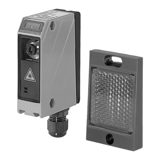
In combination with a special reflector PTKS 20x40, PTKS 50x50 (preferred type) or PTKS 100x100, the SRK 96 protective retro-reflective photoelectric sensor works as a sensor unit in an active opto-electronic protective device (AOPD) according to EN IEC 61496-2 type 2. -
Page 16: Testing Of Srk 96
Function Testing of SRK 96 The SRK 96 must be tested by switching the input voltage on the activation input on and off. If the voltage on the activation input falls to under 2 V, the switching output follows after approx. -
Page 17: Functional Safety
The maximum reaction time remains at 620 ms. When cyclical testing is otherwise produced, please observe the requirements of EN IEC 61496-1 type 2 and EN ISO 13849-1. Figure 3.4-1: Overview of test parameters of type 2 testing Leuze electronic SRK 96... - Page 18 The response time must be monitored to ensure that the cycle time of the testing is complied with (see DIN EN ISO 13849-1:2015) The SRK 96 does not test the wiring for short circuits. This must be provided by the superior testing system.
-
Page 19: Mounting And Commissioning
Mounting the SRK 96 protective retro-reflective photoelectric sensor When mounting the SRK 96, it must be ensured that the specific reflector for this purpose, i.e., the PTKS 20 x 40, PTKS 50 x 50 (preferred type) or PTKS 100 x 100, is mounted in the correct position. - Page 20 It might be necessary to replace the SRK 96 and PTKS… reflector or to mount them so that the light source is not within the direct beam path. During installation, please make sure that no strongly reflective surfaces or standard reflectors are within the immediate vicinity of the PTKS…...
- Page 21 Mounting to or between plane-parallel surfaces Attention! After aligning the SRK 96 to the PTKS… reflector (the yellow LED on the SRK 96 is illuminated), the horizontal pitch of the light axis must be checked. The reflector mounting surface must be at a right angle to the light axis (see fig. 4.4-1).
- Page 22 S = K * T + C S [mm] = Safety distance K [mm/s] = 1600 mm/s (gripping and approach speed) T [s] = Total time of the delay C [mm] = 850 mm (default value for arm length) SRK 96 Leuze electronic...
- Page 23 = Response time of the safety interface device = Stopping time of the machine Calculation example A machine with a stopping time of 500 ms and safeguarding with the SRK 96 (safety sensor) and a safety relay MSI-TR1B (safety interface) is assumed. S = K * (t...
- Page 24 Additional distance C [mm] e.g. floor [mm] 1200 , 900 300, 700.1100 Table 4.4-1: Beam spacing in accordance with EN ISO 13855 For the lowest beam, 400 mm are only permissible if allowed by the risk assessment. SRK 96 Leuze electronic...
- Page 25 5˚ 5˚ Figure 4.4-5: Minimum distance to reflective surfaces = Distance to the reflective/mirroring surface = Protected field width = Reflective/mirroring surface = Protective retro-reflective photoelectric sensor = PTKS reflector = Object Leuze electronic SRK 96...
- Page 26 = Protective field width [m] 3500 3000 2500 2000 1500 1000 Figure 4.4-7: Minimum distance to reflective surfaces as a function of the protective field width = Required minimum distance to reflective surfaces [mm] = Protective field width [m] SRK 96 Leuze electronic...
-
Page 27: Electrical Installation
The activation input (terminal 4 / at plug connection PIN 2) is active when a DC voltage of 8 V is applied. The transmitter is now working and emits visible red light. If the activation input drops below a DC voltage of 2 V, the internal test of the SRK 96 is triggered. - Page 28 Electrical installation Connection diagram of SRK 96 with MSI T + 24V + 24V SRK 96 14 15 Activ SRK 96 MSI-T State Activ SRK 96 Var. B Var. A Activ Figure 5.1-2: Connection of SRK 96 with MSI T Note! No more than three devices in series may be connected to a tester.
-
Page 29: Test
Interrupt the light beam between the transmitter and receiver (test object 50 mm) • In front of the SRK 96 and the reflector • In the middle between the SRK 96 and the reflector • Before and after the deflecting mirror It must not be possible to initiate the dangerous state during beam interruption. -
Page 30: Technical Data
Typ. operating range limit: max. attainable range without function reserve Operating range: recommended range with function reserve 1=transient protection, 2=polarity reversal protection, 3=short circuit protection for all outputs, 4=interference blanking Rating voltage 250 VAC / overvoltage category II Table 7.2-1: Technical data SRK 96 Leuze electronic... - Page 31 Typ. operating range limit: max. attainable range without function reserve Operating range: recommended range with function reserve 1=transient protection, 2=polarity reversal protection, 3=short circuit protection for all outputs, 4=interference blanking Rating voltage 250 VAC / overvoltage category II Table 7.2-1: Technical data Leuze electronic SRK 96...
-
Page 32: Dimensioned Drawings
Optical axis Device plug M12 Screwed cable gland M 16 x 1.5 for Ø 5 … 10 mm Countersinking for SK nut M 5, 4.2 deep Connection terminals Cable entry Figure 7.3-1: SRK 96 dimensioned drawing SRK 96 Leuze electronic... - Page 33 Technical data PTKS 20 x 40 PTKS 50 x 50 PTKS 100 x 100 (preferred type) Figure 7.3-2: Dimensioned drawing of PTKS… reflectors Leuze electronic SRK 96...
- Page 34 Technical data SRK 96 Leuze electronic...
Need help?
Do you have a question about the SRK 96 and is the answer not in the manual?
Questions and answers