
Related Manuals for Leuze electronic PRK3CLA Autokollimation


Summary of Contents for Leuze electronic PRK3CLA Autokollimation
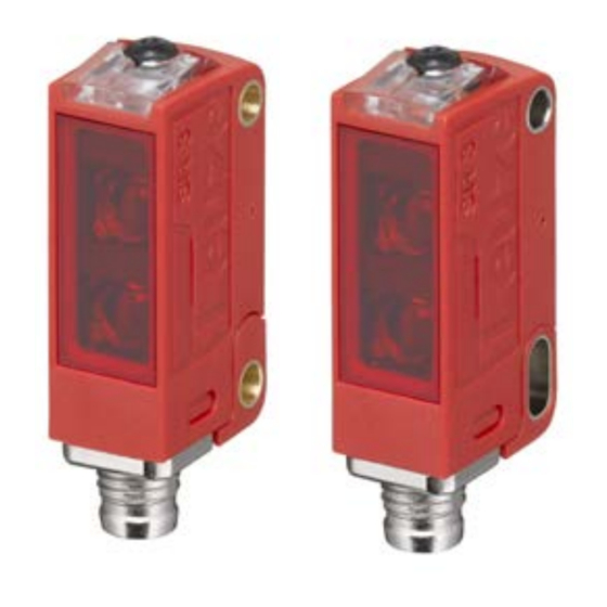
- Page 1 Laser retro-reflective photoelectric sensors PRK3CLA Autokollimation Leuze electronic GmbH + Co. KG In der Braike 1 D-73277 Owen Tel.: +49 (0) 7021 573-0 info@leuze.com • www.leuze.com...
- Page 2 1Bildteil HIGH t = 20 ... 80 ms HIGH t = 120 ... 180 ms HIGH t = 220 ... 280 ms HIGH t = 320 ... 380 ms...
-
Page 4: General Information
General information – The laser retro-reflective photoelectric sensors PRK3CL… have an opti- mized light beam propagation in the typical range of application of 0 … 1 m (not to be confused with the operating range limit, which is 0 … 3 m in combi- nation with a reflector MTKS 50x50.1). This permits the reliable recognition of the smallest of parts or the positioning of objects with maximum precision across the entire area. - Page 5 Device settings are stored fail-safe. (3) Teach at max. operating range (fac- (4) Set switching behavior (light/dark tory setting) switching) Obstruct the light path before teaching! When the function is activated, the switching output is always inverted rela- tive to the previously set state. Hold down the teach button (2 to 7 1 Hold down the teach button longer s) until the yellow and green LEDs...
- Page 6 Sensitive teach (increased sensitivity) Sensitive teach (increased sensitivity) is performed Teach button is locked Teach button may now be operated again Light switching logic Switching outputs are light switching, i.e., outputs are active, when there is no ob- ject currently in the light path. With antivalent switching outputs: OUT 1 (pin 4) light switching, OUT 2 (pin 2) dark switching.
-
Page 7: Io-Link Interface
IO-Link interface Sensors in the PRK3C…/L… variant have a dual-channel architecture. The IO- Link interface is available in accordance with specification 1.1.2 (July 2013) on pin 4 (OUT 1). You can easily, quickly and economically configure the devices via the IO-Link interface. Furthermore, the sensor transmits the process data via the IO- Link interface and makes diagnostic information available through it. -
Page 8: Device-Specific Iodd
Device input data Data bit Assignment Meaning Deactivation 0 = transmitter active, 1 = transmitter in- active Not assigned Free Not assigned Free Not assigned Free Not assigned Free Not assigned Free Not assigned Free Not assigned Free Device-specific IODD At www.leuze.com in the download area for IO-Link sensors you will find the IODD zip file with all data required for the installation. - Page 9 Function block Function Description If the function Q2 = switching output is se- Configuration Logical function of lected, the switching function corresponds to the current setting which was selected via the L/D changeover. If Q2 = inv. switching output is selected, the switching behavior of the output is inverted.
- Page 10 Observe the applicable statutory and local laser protection regula- tions. Ä The device must not be tampered with and must not be changed in any way. There are no user-serviceable parts inside the device. Ä Repairs must only be performed by Leuze electronic GmbH + Co.
Need help?
Do you have a question about the PRK3CLA Autokollimation and is the answer not in the manual?
Questions and answers