Sign In
Upload
Download
Table of Contents
Contents
Add to my manuals
Delete from my manuals
Share
URL of this page:
HTML Link:
Bookmark this page
Add
Manual will be automatically added to "My Manuals"
Print this page
×
Bookmark added
×
Added to my manuals
Manuals
Brands
Taylor Manuals
Grill
810 Series
Operator's manual
Taylor 810 Series Operator's Manual
Auto lift grills
Hide thumbs
Also See for 810 Series
:
Original service instructions
(208 pages)
1
2
Table Of Contents
3
4
5
6
7
8
9
10
11
12
13
14
15
16
17
18
19
20
21
22
23
24
25
26
27
28
29
30
31
32
33
34
35
36
37
38
39
40
41
42
43
44
45
46
47
48
49
50
51
52
53
54
55
56
page
of
56
Go
/
56
Contents
Table of Contents
Bookmarks
Table of Contents
Table of Contents
Section 1: to the Installer
Installer Safety
Site Preparation
Electrical Connections
Installation
Installation of Cable Kit
Ventilation and Clearance
Grease Disposal Container
Section 2: to the Operator
Section 3: Safety
Operate Safely
Section 4: Operator Parts Identification
L810 / G810 Exploded View
L812 Exploded View
L820 / G820 Exploded View
L822 Exploded View
L828 / G828 Exploded View
Accessories Supplied with Grill
Optional Accessories Available from Local Taylor Distributor
Section 5: User Interface
Section 6: Operating Procedures
Daily Opening Procedures
Loading Store Menu Items to USB
Loading Menu Items from USB
Daily Cleaning Procedures
Advertisement
Quick Links
1
Electrical Connections
2
L810 / G810 Exploded View
3
L812 Exploded View
4
L820 / G820 Exploded View
5
L828 / G828 Exploded View
6
Section 5: User Interface
Download this manual
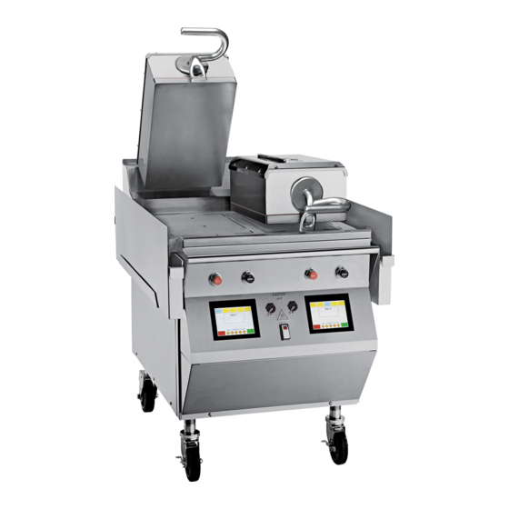
OPERATOR'S
MANUAL
Model 810, 812, 820, 822, 828 Series
Auto Lift Grills
Original Operating Instructions
9/15/10 (Original Publication)
073523-M
(Updated 7/15/2019)
Table of
Contents
Previous
Page
Next
Page
1
2
3
4
5
Advertisement
Table of Contents
Need help?
Do you have a question about the 810 Series and is the answer not in the manual?
Ask a question
Questions and answers
Related Manuals for Taylor 810 Series
Grill Taylor 810 Series Original Service Instructions
Auto gap grills (208 pages)
Grill Taylor 811 Series Operator's Manual
Auto lift gas grills (58 pages)
Grill Taylor C832 Service Manual
Mcdonald's intelligap grills (219 pages)
Grill Taylor QS11 Original Operating Instructions
Modular grills (43 pages)
Grill Taylor Intelli Gap Programming Instructions Manual
Complete multi-stage / 4:1 – cooking on iron (8 pages)
Grill Taylor C850 Series Equipment Manual
Clamshell grill for mcdonald's (67 pages)
Grill Taylor C801 Operating Instructions Manual
Wendy's grills (70 pages)
Grill Taylor QS12 Service Manual
(60 pages)
Grill Taylor L850 Operator's Manual
Active compression grills (42 pages)
Grill Taylor The Biggest Loser AG-1360-BL Instruction Manual
Mini grill (8 pages)
Grill Taylor QS11 Operating Instructions Manual
Modular (42 pages)
Grill Taylor C819 Operating Instructions Manual
Auto lift grill (49 pages)
Grill Taylor C820 Original Operating Instructions
Auto lift grills (46 pages)
Grill Taylor QS12 Operating Instructions Manual
(47 pages)
This manual is also suitable for:
820 series
812 series
828 series
L810
L812
G810
...
Show all
L820
G820
L822
L828
G828
822 series
Table of Contents
Print
Rename the bookmark
Delete bookmark?
Delete from my manuals?
Login
Sign In
OR
Sign in with Facebook
Sign in with Google
Upload manual
Upload from disk
Upload from URL


Need help?
Do you have a question about the 810 Series and is the answer not in the manual?
Questions and answers