
Related Manuals for Taylor 811 Series


Summary of Contents for Taylor 811 Series
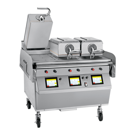
- Page 1 OPERATOR’S MANUAL Model 811, 813, 819, 821 Series Auto Lift Gas Grills Original Operating Instructions 9/15/10 (Original Publication) 073625-M (Updated 3/15/2022)
- Page 2 Only instructions originating from the factory or its authorized translation representative(s) are considered to be the original set of instructions. © 2010 Taylor Company (Updated 3/15/2022) 073625-M Any unauthorized reproduction, disclosure, or distribution of copies by any person of any portion of this work may be...
-
Page 3: Table Of Contents
Accessories Supplied with Grill ......... . . 4-5 Optional Accessories Available from Local Taylor Distributor....4-6... - Page 4 Notes: 073625-M...
-
Page 5: Section 1: To The Installer
The proper wire size and branch circuit overcurrent damage to the machine. device shall be selected according to the data label Note: All repairs must be performed by a Taylor service information and in accordance with CEC Part I 2006, technician. Section 14-100(e)(i). - Page 6 • If the supply cord is damaged, it must be replaced by a Taylor service technician to avoid a hazard. • Secure the supply cord ground lead to the machine in a location where if the cord is pulled, the main power leads will become taut before the ground lead can break loose.
- Page 7 TO THE INSTALLER Ventilation and Clearance Grease Disposal Container To ensure proper operation of this appliance, it must be If the grill is not factory-equipped with grease disposal installed so that the products of combustion are efficiently containers, the store is required to provide appropriate removed.
- Page 8 TO THE INSTALLER Notes: To the Installer Model 811, 813, 819, 821 Series...
-
Page 9: Section 2: To The Operator
To the Operator Section 2 The Taylor grills included in this manual consist of the Note: Your Taylor warranty is valid only if the parts are base model numbers 811, 813, 819, and 821. authorized Taylor parts, purchased from the local... - Page 10 TO THE OPERATOR Notes: To the Operator Model 811, 813, 819, 821 Series...
-
Page 11: Section 3: Safety
We at Taylor Company are concerned about the safety of the operator when he or she comes in contact with the grill and its parts. Taylor has gone to extreme efforts to WARNING! Failure to follow the instructions design and manufacture built-in safety features to protect below may result in severe injury or death from both you and the service technician. - Page 12 SAFETY WARNING! DO NOT use cold water or ice to IMPORTANT! DO NOT use a water jet or spray excessive water on or anywhere near the grill. cool the upper platen or the lower cook surface. Failure Failure to follow this instruction may result in serious to follow this instruction may result in: electrical shock and cause permanent electrical and mechanical damage to internal parts.
- Page 13 SAFETY CAUTION! For thorough cleaning, the grill IMPORTANT! must be pulled away from the wall. Before moving the • DO NOT obstruct the ventilation openings at the grill, remove the grease cans. Turn off the gas at the rear of this machine. quick connect shutoff valve on the flexible hose.
- Page 14 SAFETY Notes: Safety Model 811, 813, 819, 821 Series...
-
Page 15: L811 Exploded View
Operator Parts Identification Section 4 L811 Exploded View Figure 4-1 Item Description Part No. Item Description Part No. Can A.-Grease *HEM X80925 Nut-Jam 1 1/2-12 Steel 073594 Slide A.-Can Grease *L X83854 Caster-5 in. 7-5/8 Stem Rigid 078377 Panel-Side Upper-LT 073990 Caster-5 in. -
Page 16: L813 Exploded View
OPERATOR PARTS IDENTIFICATION L813 Exploded View Figure 4-2 Item Description Part No. Item Description Part No. Can A.-Grease *HEM X80925 Nut-Jam 1 1/2-12 Steel 073594 Slide A.-Can Grease *L X83854 Caster-5" 7-5/8 Stem Rigid 078377 Panel-Side Upper-LT 073990 Caster-5" 7-5/8 Swivel w/Lock 073240 Screw-10-32x3/8 SLTD Trus 024298... -
Page 17: L819 Exploded View
OPERATOR PARTS IDENTIFICATION L819 Exploded View Figure 4-3 Item Description Part No. Item Description Part No. Can A.-Grease *HEM X80925 Nut-Jam 1 1/2-12 Steel 073594 Slide-Grease Can *L X83854 Caster-5" 7-5/8 Stem Rigid 078377 Panel-Side Upper-LT 073990 Caster-5" 7-5/8 Swivel w/Lock 073240 Screw-10-32x3/8 SLTD Trus 024298... -
Page 18: L821 Exploded View
OPERATOR PARTS IDENTIFICATION L821 Exploded View Figure 4-4 Item Description Part No. Item Description Part No. Can A.-Grease *HEM X80925 Panel-Side-Lower *Right 073991 Slide-Grease Can *L X83854 Nut-Jam 1 1/2-12 Steel 073594 Panel-Side Upper-LT 073990 Caster-5" 7-5/8 Stem Rigid 078377 Screw-10-32x3/8 SLTD TRUS 024298 Caster-5"... -
Page 19: Accessories Supplied With Grill
OPERATOR PARTS IDENTIFICATION Accessories Supplied with Grill Figure 4-5 Item Description Part No. Item Description Part No. Sheet-Release - Box of 9 080595 Scraper-Teflon Wiper 075887 Retainer-Sheet Release (Reten- 080594 Strip-Replacement 075888 tion Bar) (Qty of 3) Cleaner-Stera Sheen (1 qt. Sam- 073160-SAM 3 Clip-Release Material w/Tab 072673... -
Page 20: Optional Accessories Available From Local Taylor Distributor
OPERATOR PARTS IDENTIFICATION Optional Accessories Available from Local Taylor Distributor Figure 4-6 Item Description Part No. Item Description Part No. Scraper-Blade (6 Pack) 073891 Bin A.-Tool Storage X73829 Cleaner-Stera Sheen (Case of 6, Scraper-Grill 073225 073160 1 qt. Bottles) - Page 21 User Interface Section 5 Figure 5-1 Item Description Item Description Raise Button Program Key Standby/Cook Mode Button Temperature Indicator Lights USB Cover/Connection Power Key Power Switch Function Display Clean Mode Key Menu Select Keys T-F = Top Front, T-R = Top Rear, L-P = Lower Plate User Interface Model 811, 813, 819, 821 Series...
- Page 22 USER INTERFACE Notes: User Interface Model 811, 813, 819, 821 Series...
-
Page 23: Section 6: Operating Procedures
Operating Procedures Section 6 The three-platen Model L811 has been selected to 2. Hook the release sheet retainer on the release sheet illustrate the step-by-step procedures. For grills equipped shoulder screws at the top of the upper platen. with less than three platens, perform the following steps 14351 as appropriate for your grill platen configuration. - Page 24 OPERATING PROCEDURES 4. Place the release sheet clips over the release sheet. Note: It is not necessary to change the release sheet if Press them into place over the release sheet bar at small pin holes develop on the sheet. the top of the platen.
- Page 25 Raise button, or Standby button. 13732 Figure 6-7 Note: Contact your local Taylor distributor to purchase the correct grill cleaning pad and holder. (See page 4-6.) • Do rinse both sides of the release sheet with a clean, sanitizer-soaked grill cloth to remove the cleaner.
- Page 26 OPERATING PROCEDURES When the grill is at the proper temperature, the 2. The PASSWORD screen will appear. Enter the temperature statements will no longer display and the Operator Password STORE1 and press the OK key. temperature indicators will be illuminated in green. 131020 13733 Figure 6-11...
- Page 27 OPERATING PROCEDURES ADJUST VOLUME Key Press the menu item key to be programmed. The following screen will display: The Adjust volume key displays the current volume. To 131024 increase or decrease the volume, use the up and down arrow keys. Note: To scroll at a faster rate, press and hold the arrow key.
- Page 28 OPERATING PROCEDURES Delete Item Multiple Timing Functions: There are four timing functions for clam and flat menu items. Each function has This key is used to delete the selected menu item. When a set of parameters associated with it. The functions pressed, the screen displays YES or NO.
- Page 29 OPERATING PROCEDURES Service Contact Information Key After the product has been turned, the Standby button will need to be pressed to bring the platen back down. Once Press the Service Contact Information key to view the it reaches the next set gap, the product will then cook for programmed service contact information.
-
Page 30: Loading Store Menu Items To Usb
OPERATING PROCEDURES Standby Alert Time Key 4. Enter the operator password STORE 1 and press the OK key. This is a programmable timer that can be set from 5 to 60 131020 minutes. After the selected time has expired, an alert will sound and the screen will display PUT INTO STANDBY. -
Page 31: Loading Menu Items From Usb
OPERATING PROCEDURES Patty Placement and Removal 7. Using the keyboard displayed on the control, enter a file name to save the menu item. The name can have Placement procedures of meat products on the grill must up to 8 characters and must have no spaces name. be followed. - Page 32 OPERATING PROCEDURES Patty Placement Guide Figure 6-25 6-10 Operating Procedures Model 811, 813, 819, 821 Series...
-
Page 33: Operating Procedures
OPERATING PROCEDURES Operating Procedures At the end of the cook cycle, the control will display DONE, a tone will sound, and the platen will Cooking Product automatically raise. 131031 1. Select the menu item to be cooked. When the grill is at the correct temperature, the grill temperature indicators will be green and the control will not display any temperature statements. - Page 34 OPERATING PROCEDURES To Cancel a Flat Menu Item Timing Function If the box is blank (creating a new Item), type in the desired name (up to 9 characters). A maximum of two If only one flat menu item timing function is displayed, lines of description can be used.
- Page 35 OPERATING PROCEDURES Two-Function Cook Cycle Screen Standby Procedures Whenever the grill is idle and product is not being The following is an example of a two-function cook cycle cooked, the upper platen should be placed in the screen. The two functions shown are TURN IN and STANDBY position to conserve energy.
- Page 36 OPERATING PROCEDURES Menu Parameters Cleaning after Each Run of Product To view the settings and actual temperatures for the 1. Using the grill scraper, scrape the grease on the current item, press and hold the menu item key at a lower grill surface from front to back.
-
Page 37: Daily Cleaning Procedures
OPERATING PROCEDURES 3. Using the wiper squeegee, push the grease at the rear of the lower grill surface into the grease can. Do CAUTION! Never use force to raise the upper not use the grill scraper for this step. platen. Damage to components may result. Only use the 14035 RAISE button to open the upper platen. - Page 38 OPERATING PROCEDURES 4. Put on heat-resistant gloves. 7. Repeat step 1 through step 6 for the remaining upper platen(s). 14511 8. Wash and rinse the clips and retainers in the sink. Set them aside for future use. 9. Leave the release sheets on the clean, flat surface next to the sink until further cleaning is performed.
- Page 39 OPERATING PROCEDURES 11. Use the wiper squeegee to push residual grease into the grease cans. 14506 IMPORTANT! Use the grill cleaning pad and holder identified on page 4-6 ONLY. Using any other pad and holder will damage the release sheets. 15.
- Page 40 OPERATING PROCEDURES 18. Apply grill cleaner to the platen surfaces. 14822 14634 Figure 6-58 Figure 6-56 24. Press the RAISE button to raise the lowered platen. 19. Apply grill cleaner to the back side of the upper 25. Lightly scrub the front side of the platens and the platens.
- Page 41 OPERATING PROCEDURES 28. Lightly scrub the outer edges of the right and left 14636 platens. 29. Press the STANDBY button twice to lower one of the platens. Model 811 Only: Press the STANDBY button twice to lower the center platen. Lightly scrub both sides of the center platen.
- Page 42 42. Use the squeegee to remove the cleaner from the Figure 6-66 grill surface. Note: Contact your local Taylor distributor to purchase 14548 the correct grill cleaning pad and holder. (See page 4-6.) 44. Place the release sheets flat on the lower grill surface.
- Page 43 OPERATING PROCEDURES For 24-Hour Stores Only 45. Rinse both sides of the release sheets with a clean, sanitizer-soaked grill cloth. Re-install the release sheets on the opposite side than 14544 previously used. Secure the sheets with the release sheet clips and retainers. Start up the grill per instructions starting on page 6-1.
- Page 44 OPERATING PROCEDURES 3. Place the power switch in the OFF position. 14583 Figure 6-72 6-22 Operating Procedures Model 811, 813, 819, 821 Series...
-
Page 45: Section 7: Troubleshooting Guide
Troubleshooting Guide Section 7 Table 7-1 Problem Probable Cause Remedy a. Check the power 1. One side of the grill will not heat. The a. One of the power cords may have come screen will display CALL SERVICE, NO loose or unplugged from the wall during connection. - Page 46 TROUBLESHOOTING GUIDE Problem Probable Cause Remedy 9. The screen displays PLATEN NOT a. An item may be under platen, preventing it a. Remove the item and try LATCHED. CALL SERVICE-LATCH. IS from latching. again. AN OBJECT STUCK UNDER THE b. The pneumatic system is faulty. b.
- Page 47 TROUBLESHOOTING GUIDE Problem Probable Cause Remedy 12.The product is undercooked or a. The release sheet is worn. a. Replace the release sheet. overcooked. b. Incorrect cooking time. b. Reset the processor control for the correct time. c. Incorrect temperature setting. c.
- Page 48 TROUBLESHOOTING GUIDE Problem Probable Cause Remedy 14.The product is not cooking evenly. a. The upper platen or lower grill surface is a. Follow closing procedures to not clean and/or has carbon buildup. properly clean the upper platen and the lower grill surface and to remove ...
-
Page 49: Gas Zones Only
TROUBLESHOOTING GUIDE Gas Zones Only Problem Probable Cause Remedy 1. The display reads a. Controller may need to be reset, or there may be an a. Verify that the gas supply is turned IGNITION TERMINATED issue with the gas pressure. on and connected to the grill. - Page 50 TROUBLESHOOTING GUIDE Notes: Troubleshooting Guide Model 811, 813, 819, 821 Series...
-
Page 51: Section 8: Limited Warranty On Equipment
LIMITED WARRANTY Taylor warrants the Product against failure due to defect in materials or workmanship under normal use and service as follows. All warranty periods begin on the date of original Product installation. If a part fails due to defect during the applicable warranty period, Taylor, through an authorized Taylor distributor or service agency, will provide a new or ... - Page 52 Taylor. 5. Replacement of wear items designated as Class 000 parts in the Taylor Operator’s Manual, as well as any release sheets and clips.
- Page 53 LEGAL REMEDIES The owner must notify Taylor in writing, by certified or registered letter to the following address, of any defect or complaint with the Product, stating the defect or complaint and a specific request for repair, replacement, or other correction of the Product under warranty, mailed at least thirty (30) days before pursuing any legal rights or remedies.
- Page 54 LIMITED WARRANTY ON EQUIPMENT Notes: Limited Warranty on Equipment Model 811, 813, 819, 821 Series...
- Page 55 Taylor warrants the Parts against failure due to defect in materials or workmanship under normal use and service as follows. All warranty periods begin on the date of original installation of the Part in the Taylor machine. If a Part fails due to defect during the applicable warranty period, Taylor, through an authorized Taylor distributor or service agency, will provide a new or remanufactured Part, at Taylor’s option, to replace the failed defective Part at no charge for the Part.
- Page 56 Taylor. 5. Replacement of wear items designated as Class 000 Parts in the Taylor Operator's Manual, as well as any release sheets and clips for the Product's upper platen assembly.
- Page 57 LEGAL REMEDIES The owner must notify Taylor in writing by certified or registered letter to the following address of any defect or complaint with the Part, stating the defect or complaint and a specific request for repair, replacement, or other correction of the Part under warranty, mailed at least thirty (30) days before pursuing any legal rights or remedies.
- Page 58 LIMITED WARRANTY ON PARTS Notes: Limited Warranty on Parts Model 811, 813, 819, 821 Series...
Need help?
Do you have a question about the 811 Series and is the answer not in the manual?
Questions and answers