Advertisement
Table of Contents
- 1 Table of Contents
- 2 Warranty
- 3 Introduction
- 4 Safety
- 5 Parts Identification/Function and Exploded View
- 6 Important to the Operator
- 7 Equipment Set-Up and Close Procedures
- 8 Menu Screens
- 9 Daily Cleaning Procedures
- 10 Troubleshooting Guide
- 11 Limited Warranty on Equipment
- 12 Limited Warranty on Parts
- 13 Ordering/Service
- Download this manual
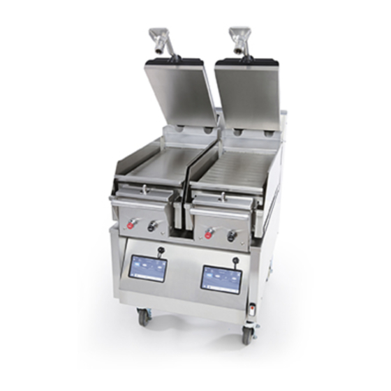
Clamshell Grill
Taylor Models C850, C852, C854 & C856
This equipment chapter is to be inserted
in the appropriate section of the
Equipment Manual.
Manufactured exclusively for
McDonald's®
By
Taylor Company®
a division of Carrier Commercial
Refrigeration, Inc.
750 N. Blackhawk Blvd.
Rockton, IL 61072
®
McDonald's
Hotline:
(877-435-7623)
service@taylor-company.com
TABLE OF CONTENTS
. . . . . . . . . . . . . . . . . . . . . . . . . . . . . . . . . . . . . . . . . . . . . . . . . . . . . . . . . . . .
. . . . . . . . . . . . . . . . . . . . . . . . . . . . . . . . . . . . . . . . . . . . . . . . . . . . . . . .
. . . . . . . . . . . . . . . . . . . . . . . . . . . . . . . . . . . . . . . . . . . . . . . . . . . . . . . . . . . . . . .
. . . . . . . . . . . . . . . . . . . . . . . . . . . . . . . . . . . . . . . . . . . . . . . . . . . . . . .
Warranty
A warranty checkout card is shipped with every new grill that leaves the factory. The warranty checkout card is packed
in an envelope which also contains this operator's manual. Refer to the warranty checkout card and the warranty
classifications listed in the Parts Identification/Function section when service is performed on your grill.
It is recommended that the operator take the necessary time to carefully read through the complete warranty information.
contained in the warranty checkout card. Any questions or unclear statements found within the card should be made
clear to you upon delivery of the grill. Thoroughly understand your warranty protection before you begin operation.
For any questions pertaining to the Taylor Warranty, please contact your authorized Taylor distributor or Taylor
Company, a division of Carrier Commercial Refrigeration, Inc., Rockton, Illinois 61072.
This manual is for the exclusive use of licensees and employees of McDonald's Corporation.
E2016 McDonald's Corporation
All Rights Reserved
. . . . . . . . . . . . . . . . . . . . . . . . . . . . . . . . . . . . . . . .
. . . . . . . . . . . . . . . . . . . . . . . . . . . . . . . . . . . . . . . .
. . . . . . . . . . . . . . . . . . . . . . . . . . . . . . . . . . . . . . . . . . . .
. . . . . . . . . . . . . . . . . . . . . . . . . . . . . . . . . . .
. . . . . . . . . . . . . . . . . . . . . . . . . . . . . . . . . . . . . . . .
. . . . . . . . . . . . . . . . . . . . . . . . . . . . . . . . . . . . . . . . . . . . . . . . . . .
October, 2016 (Original Publication)
EM SD11
. . . . . . . . . . . . . . .
. . . . . . . . . . . . . . . . . . . . . . . . .
The United States of America
1
1
1
4
18
22
26
39
56
58
60
63
Printed in
Advertisement
Table of Contents

Related Manuals for Taylor C850 Series


Summary of Contents for Taylor C850 Series
-
Page 1: Table Of Contents
Thoroughly understand your warranty protection before you begin operation. For any questions pertaining to the Taylor Warranty, please contact your authorized Taylor distributor or Taylor Company, a division of Carrier Commercial Refrigeration, Inc., Rockton, Illinois 61072. -
Page 3: Warranty
Failure to comply may result in equipment damage or personal injury. This manual should be kept in a safe place for future reference. For any questions pertaining to the Taylor Warranty, please contact Taylor Company, Rockton, Illinois 61072. - Page 4 The main power supplies to the machine must be disconnected prior to performing any repairs. For Cord Connected Units: Only Taylor authorized service technicians or licensed electricians may install a plug or replacement DO NOT obstruct the ventilation openings at cord on these units.
- Page 5 HAZARD COMMUNICATION STANDARD (HCS) - The procedure(s) in this manual include the use of chemical products. These chemical products If the crossed out wheeled bin symbol is will be highlighted with bold faced letters affixed to this product, it signifies that this product is followed by the abbreviation (HCS) in the text compliant with the EU Directive 2012/19/EU as well portion of the procedure.
- Page 6 C850 Exploded View Figure 1...
-
Page 7: Parts Identification/Function And Exploded View
Parts Identification/Function and Exploded View C850 Exploded View (See Figure 1.) ITEM PART NO. DESCRIPTION QTY. FUNCTION WARR. CLASS X84969 CAN A.-GREASE-L Container for grease. X84224 SHROUD-UPPER SIDE Metal bracket that the grease can slides into, securing it next to the lower grill plate. - Page 8 C852 Exploded View Figure 2...
- Page 9 C852 Exploded View (See Figure 2.) ITEM PART NO. DESCRIPTION QTY. FUNCTION WARR. CLASS X84969 CAN A.-GREASE-L Container for grease. X84224 SHROUD A.-UPPER*LFT Metal bracket that the grease can slides into, securing it next to the lower grill plate. 070695 SCREW-10-32X1/2 PHIL Fastens bumper onto panel.
- Page 10 C850/C852 Right Side View (See Figure 3.) Figure 3 ITEM PART NO. DESCRIPTION QTY. FUNCTION WARR. CLASS X84169-SER Kit A.-Actuator Plate Positions the cooking surface. (C850) (C852)
- Page 11 C850/C852 left Side View (See Figure 4.) Figure 4 ITEM PART NO. DESCRIPTION QTY. FUNCTION WARR. CLASS 084170 Handle-Grill The handle clicks in to the platen latch when in the down position. (C850) (C852)
- Page 12 C854 Exploded View Figure 5...
- Page 13 C854 Exploded View (See Figure 5.) ITEM PART NO. DESCRIPTION QTY. FUNCTION WARR. CLASS X84971 CAN A.-GREASE-L Container for grease. X84248 SHROUD A.-UPPER*LFT Metal bracket that the grease can slides into, securing it next to the lower grill plate. 070695 SCREW-10-32X1/2 PHIL Fastens bumper onto panel.
- Page 14 C856 Exploded View Figure 6...
- Page 15 C856 Exploded View (See Figure 6.) ITEM PART NO. DESCRIPTION QTY. FUNCTION WARR. CLASS X84971 CAN A.-GREASE-L Container for grease. X84248 SHROUD A.-UPPER*L Metal bracket that the grease can slides into, securing it next to the lower grill plate. 070695 SCREW-10-32X1/2 PHIL Fastens bumper onto panel.
- Page 16 C854/C856 Right Side View (See Figure 7.) Figure 7 ITEM PART NO. DESCRIPTION QTY. FUNCTION WARR. CLASS 084830 Handle-Platen The handle clicks in to the platen latch when in the down position. (C854) (C856)
- Page 17 C854/C856 left Side View (See Figure 8.) Figure 8 ITEM PART NO. DESCRIPTION QTY. FUNCTION WARR. CLASS 084549 Bumper Protects the grill from damage.
- Page 18 Accessories (See Figure 9.) ITEM PART NO. DESCRIPTION FUNCTION WARR. CLASS 072673 Clip-Release Secures the release material to the Material-w/tab front and sides of the platen. 084366 Sheet-Release Non-stick barrier used to protect the upper platen. Box of 3 084387 Sheet-Lower Release Non-stick barrier used to protect the lower cook surface.
- Page 19 Notes:...
-
Page 20: Important To The Operator
Important to the Operator Important to the Operator Exploded View (See Figure 10.) ITEM DESCRIPTION FUNCTION Fan Interlock Switch Activates power to the grill and the exhaust fans. Clean Key Takes the grill into the ready mode for cleaning. Settings Key Displays a pass code screen to allow the manager to enter the pass code and enter the Manager menu. - Page 21 Important to the Operator Figure 10...
- Page 22 To better communicate in the International arena, the words on many of our operator keys have been replaced by symbols to indicate their functions. Your Taylor equipment is designed with these International symbols. The following chart identifies the symbol definitions.
- Page 23 Other Symbol Definitions = X Key - Do not save current changes. = Recipe Filter Key - Allows the user to Exits current screen. choose the grill mode (Manual/Auto) and toggle between AM, PM and ALLDAY. = Recipe Management Key - Allows the = Auto Calibrate Key - Pressing this key user to toggle, change the order of re...
-
Page 24: Equipment Set-Up And Close Procedures
Equipment Set-Up and Close The release sheet must be changed when: Procedures Product sticks to the release sheet. Carbon builds up, causing problems in taste or appearance. The two platen Model C852 has been selected to illustrate the step-by-step procedures in this manual. For There is a tear in the release sheet in the grills equipped with less than two platens, perform the cooking area. - Page 25 Once the grill reaches the desired set point, the Pressing will display a heat up timer. See Auto Calibration screen (See Figure 37.) will Figure 14. appear for 40 seconds and then close. The screen will then display the following. See Figure 16. Figure 16 Figure 14 Press the Menu key...
- Page 26 Selecting the Clean key will cause the grill Select the Cook Time key . See Figure 21. to enter the Clean mode. See page 35 for cleaning instructions. See Figure 19. Figure 21 If the Cook Time is correct, press the Figure 19 confirm.
- Page 27 Choose Grill Mode (See page 31 for more Put on heat-resistant gloves. See Figure 26. information.) or AM/PM Toggle. See Figure 24. Figure 26 Figure 24 Clean the grill with a sanitizer-soaked grill cloth to remove any debris on the grill. See Figure 27. Choose AM, PM or ALL DAY.
-
Page 28: Menu Screens
Using a clean squeegee, spread the flakes on the cooking zone. See Figure 29. Menu Screens Note: For all screens that display a key and an key: Pressing the key saves the selection and exits the screen. Pressing the key exits the screen without saving the selection. - Page 29 Manager Menu - Passcode Access Auto Level Key Additional access to menu screens is available through Press the Auto Level key . (Must be in Standby mode.) See Figure 35. the Manager Menu. To access the Manager Menu, press the Settings key .
- Page 30 Allow the grill to reach the temperature set point. Date/Time Key When the temperature set point is reached, install The Date/Time screen is used to enter the date and time the lower release sheets. of day. When the Date/Time key is pressed, three keys are displayed.
- Page 31 About Key To enter the time, press the Time key . Enter the hour, minute and AM/PM, using the up and down arrow The About key is used to display information about keys. Press the key to confirm the selection. the grill, including the model, bill of material (BOM), See Figure 43.
- Page 32 Brightness Key Font Limits Key The Brightness key is used to display the current The Font Limits Key allows you to change the size brightness setting. To change the setting, use the up and of the screen font. See Figure 49. down arrow keys.
- Page 33 Copy To / Copy From Keys Grill Mode Key After inserting a USB drive, select the COPY TO key. Touching this key will generate a .CSV file. This can be Press the Grill mode key . Select Manual or Auto. opened in Microsoft Excel.
- Page 34 Cooking Product Recipe Management Choose the Recipe Management key . See Figure Press the Home key. Select the desired product. See Figure 55. What appears is dependent upon the grill mode. Figure 57 Select the EDITING key. See Figure 58. Figure 55 Select the Standby button.
- Page 35 Select CREATE RECIPE to create a new recipe. See Type the name of your new recipe. See Figure 63. Figure 60. Figure 63 Figure 60 Select the Recipe See Figure 61. Figure 61 If the recipe name is correct, press the to confirm.
- Page 36 Patty Placement Placement procedures of meat products must be followed on the grill. Meat must be placed on the lower grill platen, two patties at a time, from front to back, per the patty placement guide on page 35. When the cook cycle is complete, the upper platen will raise.
- Page 37 Models C850, C852, C854, C856 Next Generation Grill 10:1, 4:1, Sausage, Circular Bacon, and Angus Patty Placement Guide Figure 64 Note: Patty placement procedures for International Markets may differ. Follow the recommendations of your local McDonald's authorities.
- Page 38 Standby Procedures Cleaning After Each Run of Product (Grills Using Lower Release Sheets) Whenever the grill is idle and product is not being cooked, the upper platen must be placed in the Note: This manual contains separate procedures for STANDBY position. grills that use lower release sheets and for grills that do To place the upper platen in the STANDBY not use lower release sheets.
- Page 39 Carefully squeegee the air bubbles from center to Using the grill scraper, scrape the grease on the side, making sure the release sheet does not lower grill plate from front to back. Do not scrape become folded or creased. across the rear of the lower grill plate with the grill scraper.
- Page 40 Use the grill cloth to clean the rear grease shield The Wash pail key displays the time since and the bullnose areas, as needed during operation. the grill was last cleaned and the length of time Note: To increase the life of the release sheet, wipe it it took to clean the grill.
-
Page 41: Daily Cleaning Procedures
Remove the upper and lower release sheets n the grill. See Figure 77. CAUTION: Never use force to raise the upper platen. Damage to components may result. Only use the RAISE button to open the upper platen. Press the Menu key until the Clean key is displayed. - Page 42 Use the sanitizer-soaked grill cloth to clean the Rinse the upper and lower release sheets with a exposed surfaces of the upper and lower release separate sanitizer-soaked grill cloth. Wipe until the sheets. See Figure 80. grill cleaner residue has been fully removed. See Figure 83.
- Page 43 Spray a clean sanitizer-soaked grill cloth once with Using the grill squeegee to push residual grease grill cleaner. Wipe the soiled side of the release into the grease cans. See Figure 89. sheet until clean. See Figure 86. Figure 89 Remove the Rear Grease Guard.
- Page 44 Using the Kay Grill Cleaning Pad Holder, Spread the grill cleaner thoroughly on the lower distribute the grill cleaner around the upper platens surface to ensure full coverage. See Figure 95. to ensure full coverage. See Figure 92. Figure 95 Figure 92 Scrub the upper and lower plate with the grill Remove the cap from the dosing bottle and...
- Page 45 Remove and empty the grease cans and take to the Scrub the lower plate sides. Repeat until the sides 3-compartment sink. Leave at the sink until the are fully covered. See Figure 101. grill cleaning is finished. Continue through the “Clean Mode”.until the lower plate raises.
- Page 46 Rinse the upper and lower plates with a clean, If not using lower release sheets, skip to step 44. sanitizer-soaked grill cloth. Also rinse the surrounding areas such as the hood, bull nose and rear grease guard. See Figure 104. Figure 106 Install the lower release sheets.
- Page 47 Place the fan interlock switch in the OFF position Flip the grill pad over and replace on the tool for if the restaurant is closing: otherwise return it to the next grill cleaning. the appropriate setting for cooking. See Figure 109 Wash, rinse and sanitize all of the utensils and tools used to clean the grill at the 3-compartment sink.
- Page 48 After the grill pad has cooled, remove, wash, and Press the Clean key rinse it thoroughly at the 3-compartment sink. Turn the grill pad over and re-install on the grill pad holder. Press the Full Clean key Wash, rinse, and sanitize all utensils and tools used to clean the grill at the 3-compartment sink.
- Page 49 Wipe the exposed surface of the release sheets with a clean, sanitizer-soaked grill cloth. See Figure 116. Figure 119 Remove the release sheet locking clips and the Figure 116 upper release sheets. Wash and rinse the clips in the 3-compartment sink. If necessary, soak them in Spray a clean sanitizer-soaked grill cloth with one a hot solution of SolidSense APSC to remove spray of grill cleaner.
- Page 50 Spray a clean, sanitizer-soaked grill cloth once After spraying the sides, spray the surface of each with grill cleaner. Wipe the soiled side of the upper platen three times to cover the bottom, release sheet until clean. See Figure 122. middle and the top.
- Page 51 Remove the cap from the dosing bottle and Scrub the upper and lower plate with the grill squeeze the bottle to fill the dosing cup as marked cleaning tool and pad. See Figure 130. ½ oz.. See Figure 93. Figure 130 If needed, scrub the upper platen with the KAY Figure 127 Double-Sided Grill Brush.
- Page 52 To clean the lower plate sides, pull out the grill Remove the sock pad from the flat paddle tool and and raise the lower plates. See Figure 133. snap on the sanitizer-soaked mop sock. Clean in between and behind the platens, the rear grease guard and surrounding areas such as the hood and bullnose.
- Page 53 Reinstall the upper release sheets prior to using. Re-install the rear grease guard. See Figure 142. See Figure 139. Figure 142 Bring the cleaning tools to the 3-compartment Figure 139 sink. Rinse or launder the mop sock; then place it in a clean sanitizer pail.
- Page 54 Quarterly Recovery Mode Procedures The Recovery Mode is on. See Figure 144. (Follow the “McD Grill Recovery Cleaning Procedure” from EcoLab) Note: Use new and clean tools for Recovery application. Figure 144 Press the Standby button to start the recovery Note: PPE (gloves, apron and a face shield) should be process.
- Page 55 Remove and empty the grease cans, then rinse and Put Personal Protective Equipment on (gloves, replace. See Figure 147. face shield, apron). See Figure 150. Figure 147 Figure 150 Remove all of the clips, bars and release sheets Wipe the upper and lower plates with a clean before Recovery cleaning.
- Page 56 Note: If needed, pull the grill out from the wall and Note: Make sure to coat the entire surface of the lower stand to the side of the grill to reach the back side of the plate. Use the Kay Grill Cleaning Pad Holder with Pad upper platens.
- Page 57 Scrape carbon buildup off of all surfaces of the Note: In order to scrub all of the edges of the upper upper platens (especially the back and corners) platens, one upper platen will need to be lowered to be able to reach the inside edge of both platens with the with the scraper.
-
Page 58: Troubleshooting Guide
Troubleshooting Guide WARNING: Improper installation, adjust DANGER: Use extreme care during electrical ment, alteration, service or maintenance can circuit tests. Live circuitry may be exposed. cause property damage, injury or death. Read the installation, operating and maintenance instructions thoroughly before installing or The grill must be pulled away from the wall for servicing this equipment. - Page 59 PROBLEM PROBABLE CAUSE REMEDY Thermocouple X Open Internal component failure. Call for service. Thermocouple X Shorted 3 phase cord has become Reseat the 3 phase plug. unplugged from the wall. If the problem still remains, internal Call for service. component failure The grill is making loud whistling The egg ring is dirty and causing Clean the egg ring.
-
Page 60: Limited Warranty On Equipment
Two (2) years In addition, during the two (2) year period commencing on the date of original installation of the Product, Taylor will also provide, through an authorized Taylor distributor or service agency, all service needed to replace the failed defective part at no charge for the service. - Page 61 LEGAL REMEDIES The owner must notify Taylor in writing, by certified or registered letter to the following address, of any defect or complaint with the Product, stating the defect or complaint and a specific request for repair, replacement, or other correction of the Product under warranty, mailed at least thirty (30) days before pursuing any legal rights or remedies.
-
Page 62: Limited Warranty On Parts
Taylor warrants the Parts against failure due to defect in materials or workmanship under normal use and service as follows. All warranty periods begin on the date of original installation of the Part in the Taylor unit. If a Part fails due to defect during the applicable warranty period, Taylor, through an authorized Taylor distributor or service agency, will provide a new or re-manufactured Part, at Taylor’s option, to replace the failed defective Part at no charge for the... - Page 63 Parts or the units in which they are installed repaired or altered in any way so as, in the judgment of Taylor, to adversely affect performance, or normal wear or deterioration.
- Page 64 LEGAL REMEDIES The owner must notify Taylor in writing, by certified or registered letter to the following address, of any defect or complaint with the Part, stating the defect or complaint and a specific request for repair, replacement, or other correction of the Part under warranty, mailed at least thirty (30) days before pursuing any legal rights or remedies.
-
Page 65: Ordering/Service
Ordering/Service Information Taylor Distributor: Parts Warranty Address: See the Limited Warranty on Parts section starting on Telephone: page 60. Date of Installation: Note: Constant research results in steady improvements; therefore, information in this manual is Data Label subject to change without notice. - Page 66 Notes:...
- Page 67 084949-M...
Need help?
Do you have a question about the C850 Series and is the answer not in the manual?
Questions and answers