
Related Manuals for Taylor 810 Series


Summary of Contents for Taylor 810 Series
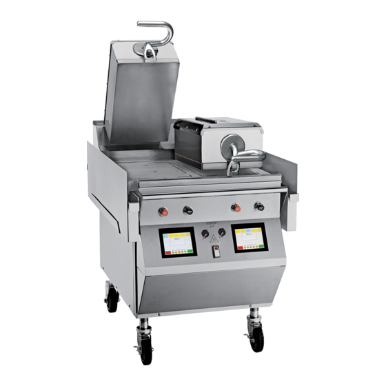
- Page 1 SERVICE MANUAL Model 810, 812, 820, 822, 828 Series Auto Gap Grills Original Service Instructions 6/24/11 (Original Publication) 073523-S (Updated 6/11/2019)
- Page 2 CAUTION: Information in this manual is intended to be used by Taylor service technicians only. Note: Continuing research results in steady improvements; therefore, information in this manual is subject to change without notice. Note: Only instructions originating from the factory or its authorized translation representative(s) are ...
-
Page 3: Table Of Contents
Table of Contents Section 1: Introduction Safety ......................... 1-2 General Installation Instructions................. 1-4 Environmental Notices ..................1-5 Model C810 Specifications................. 1-7 Model L810, G810 Specifications ..............1-9 Model C812 Specifications................1-11 Model L812 Specifications ................1-13 Model C820 Specifications................1-15 Model L820, G820 Specifications .............. - Page 4 Section 4: Parts Warranty Explanation ..................4-2 Service Parts ......................4-4 Accessories ......................4-62 Section 5: Parts List C810, L810, and G810 ..................5-2 C812 and L812 ....................5-15 C820, L820, and G820 ..................5-28 C822 and L822 ....................5-44 L828 and G828....................5-54 Section 6: Wiring Diagrams Model 810......................6-2 Model 812......................6-4 Model 820......................6-6...
-
Page 5: Section 1: Introduction
Section 1: Introduction • Safety • General Installation Instructions • Environmental Notices • Model C810 Specifications • Model L810, G810 Specifications • Model C812 Specifications • Model L812 Specifications • Model C820 Specifications • Model L820, G820 Specifications • Model C822 Specifications •... -
Page 6: Safety
INTRODUCTION Safety We at Taylor Company are deeply committed to manufacturing safe operating and serviceable machines. The many built-in safety features that are part of all WARNING! Take caution to protect eyes, Taylor machines are aimed at protecting operators and lungs, and all parts of the body from potential harm when trained service technicians alike. - Page 7 INTRODUCTION CAUTION! This grill must be installed on a WARNING! Only install this machine in a level surface. Failure to comply may result in personal location where its use and maintenance is restricted to injury or machine damage. trained personnel. Failure to comply may result in personal injury.
-
Page 8: General Installation Instructions
When uncrating the machine, inspect the machine for damage. Report any damage to your Taylor distributor. This machine is made in the USA and has USA sizes of NOTICE! Machines that are permanently hardware. All metric conversions are approximate and connected to fixed wiring and for which leakage currents vary in size. -
Page 9: Environmental Notices
In order to comply with NSF Standard 4 requirements, an appropriate grease disposal container must be provided. This container is supplied by the KES, not the Taylor DANGER! The main power supply(s) must be Company. - Page 10 INTRODUCTION China RoHS2 Hazardous Substances Part Name (Pb) (Hg) (Cd) (Cr (VI)) (PBB) (PBDE) (Sheet metal parts) (Other metal parts) (Plastic parts) (Coil assembly) (Air Compressor) (Circuit breaker and contactors) (Transformer) (Thermistors/Transducers) (Cable/Adaptor) (Labels and insulations) (PCBA’s) (Fittings and hardware) (Bushings and bearings) SJ/T 11364 O:...
-
Page 11: Model C810 Specifications
Electrical Chart for the proper electrical requirements. 864 mm) The grill is manufactured to be permanently connected. Floor Clearance: 5-3/16 in. to 10-3/16 in. (132 mm to Consult your local Taylor distributor for receptacle 259 mm) specifications, as local codes allow. (Casters may be adjusted.) - Page 12 INTRODUCTION C810 Specifications (Continued) Figure 1-1 Introduction Model 810, 812, 820, 822, 828 Series...
-
Page 13: Model L810, G810 Specifications
Electrical Chart for the proper electrical requirements. 864 mm) The grill is manufactured to be permanently connected. Floor Clearance: 5-3/16 in. to 10-3/16 in. (132 mm to Consult your local Taylor distributor for receptacle 259 mm) specifications, as local codes allow. (Casters may be adjusted.) - Page 14 INTRODUCTION L810, G810 Specifications (Continued) Figure 1-2 1-10 Introduction Model 810, 812, 820, 822, 828 Series...
-
Page 15: Model C812 Specifications
864 mm) The grill is manufactured to be permanently connected. Floor Clearance: 5-3/16 in. to 10-3/16 in. (132 mm to Consult your local Taylor distributor for receptacle 259 mm) specifications, as local codes allow. The restraining cable is included. - Page 16 INTRODUCTION C812 Specifications (Continued) Figure 1-3 1-12 Introduction Model 810, 812, 820, 822, 828 Series...
-
Page 17: Model L812 Specifications
864 mm) The grill is manufactured to be permanently connected. Floor Clearance: 5-3/16 in. to 10-3/16 in. (132 mm to Consult your local Taylor distributor for receptacle 259 mm) specifications, as local codes allow. The restraining cable (Casters may be adjusted.) is included. - Page 18 INTRODUCTION L812 Specifications (Continued) Figure 1-4 1-14 Introduction Model 810, 812, 820, 822, 828 Series...
-
Page 19: Model C820 Specifications
Electrical Chart for the proper electrical requirements. 864 mm) The grill is manufactured to be permanently connected. Floor Clearance: 6-3/4 in. to 11-3/4 in. (172 mm to Consult your local Taylor distributor for receptacle 299 mm) specifications, as local codes allow. (Casters may be adjusted.) - Page 20 INTRODUCTION C820 Specifications (Continued) Figure 1-5 1-16 Introduction Model 810, 812, 820, 822, 828 Series...
-
Page 21: Model L820, G820 Specifications
Electrical Chart for the proper electrical requirements. 864 mm) The grill is manufactured to be permanently connected. Floor Clearance: 6-3/4 in. to 11-3/4 in. (172 mm to Consult your local Taylor distributor for receptacle 299 mm) specifications, as local codes allow. (Casters may be adjusted.) - Page 22 INTRODUCTION L820, G820 Specifications (Continued) Figure 1-6 1-18 Introduction Model 810, 812, 820, 822, 828 Series...
-
Page 23: Model C822 Specifications
Electrical Chart for the proper electrical requirements. 864 mm) The grill is manufactured to be permanently connected. Floor Clearance: 6-3/4 in. to 11-3/4 in. (172 mm to Consult your local Taylor distributor for receptacle 299 mm) specifications, as local codes allow. (Casters may be adjusted.) - Page 24 INTRODUCTION C822 Specifications (Continued) Figure 1-7 1-20 Introduction Model 810, 812, 820, 822, 828 Series...
-
Page 25: Model L822 Specifications
Electrical Chart for the proper electrical requirements. 864 mm) The grill is manufactured to be permanently connected. Floor Clearance: 6-3/4 in. to 11-3/4 in. (172 mm to Consult your local Taylor distributor for receptacle 299 mm) specifications, as local codes allow. (Casters may be adjusted.) - Page 26 INTRODUCTION L822 Specifications (Continued) Figure 1-8 1-22 Introduction Model 810, 812, 820, 822, 828 Series...
-
Page 27: Model L828, G828 Specifications
Cooking Surface Height: 29 in. to 32 in. (737 mm to requirements. The grill is manufactured to be 813 mm) permanently connected. Consult your local Taylor Floor Clearance: 3-11/16 in. to 6-11/16 in. (93 mm to distributor for receptacle specifications, as local codes 169 mm) allow. - Page 28 INTRODUCTION L828, G828 Specifications (Continued) Figure 1-9 1-24 Introduction Model 810, 812, 820, 822, 828 Series...
-
Page 29: Patty Placement And Removal Guide
INTRODUCTION Patty Placement and Removal Guide Placement procedures of meat products must be Patties must be removed immediately after the upper followed on the grill. The meat must be placed on the platen has been raised to the Open position and after the lower grill surface from front to back. - Page 30 INTRODUCTION Patty Placement & Removal Guide (continued) C Series Grills (Shorter Platen Version) 6 patties maximum 8 patties maximum 3-3/4 in. (95 mm) dia. 4-3/4 in. (120 mm) dia. Figure 1-11 1-26 Introduction Model 810, 812, 820, 822, 828 Series...
-
Page 31: Section 2: Controls And Systems
Section 2: Controls and Systems • Control Keys • Control Overview • Controls • Software Loading Procedures • Electrical Power Distribution • Amp Draw • Gapping Procedures • Pneumatic System • Heating Elements Controls and Systems Model 810, 812, 820, 822, 828 Series... -
Page 32: Control Keys
CONTROLS AND SYSTEMS Control Keys Figure 2-1 Item Description Item Description RAISE Button Temperature Indicator Lights STANDBY/Cook Mode Button Power Key Master Power Switch Function Display CLEAN Mode Key Menu Select Keys PROGRAM Key USB Cover *T-F = Top Front, T-R = Top Rear, B-F = Bottom Front, B-M = Bottom Middle, ... -
Page 33: Control Overview
CONTROLS AND SYSTEMS Control Overview Figure 2-2 Controls and Systems Model 810, 812, 820, 822, 828 Series... -
Page 34: Controls
CONTROLS AND SYSTEMS Controls User Menu Press the EXIT key to return to the User Menu. The control will automatically return to the User Menu if no The control interface can store up to 75 active menu keys are pressed within 20 seconds. items. - Page 35 CONTROLS AND SYSTEMS Menu Parameters 131052 To view the settings and actual temperatures for the current item, press and hold the menu item key a minimum of 5 seconds. The screen will display the cook time, gap setting, temperature set points, and actual temperature readings for each zone for that menu item.
- Page 36 CONTROLS AND SYSTEMS ADJUST VOLUME Key 131020 This option sets the alert volume. The volume is adjustable from 0 to 10. 131022 Figure 2-9 The PROGRAM MODE screen will display. 131021 Figure 2-11 MENU EDIT Key The MENU EDIT key is used to program a new menu item or make changes to an existing one.
- Page 37 CONTROLS AND SYSTEMS Delete Item 131024 This key is used to delete the selected menu item. When pressed, the screen displays YES or NO. Selecting YES removes the item from the control memory. TOP TEMP This key displays the current set point temperature for the platen.
- Page 38 CONTROLS AND SYSTEMS Multiple Gap Function—Link Pressing function one, function two, or function three will bring up the next function in the list. A multi-function Anytime a second or third timing function is programmed Cook cycle is useful when cooking products that are into a menu item, the Link function is automatically extremely thick or products that have varying activated to YES.
- Page 39 CONTROLS AND SYSTEMS SERVICE CONTACT INFO. Key STANDBY ALERT TIME Key The service provider inserts their contact information This is a programmable timer that can be set from 5:00 (name, telephone number, and e-mail) on this screen. minutes to 60:00 minutes. After the selected time has Press the EXIT key to return to the previous page.
- Page 40 CONTROLS AND SYSTEMS Two-Function Cook Cycle Screen 2. To raise the upper platen to the Open position to resume cooking, press the RAISE button. The following is an example of a Two-Function Cook 14282 Cycle Screen. The two functions shown are TURN IN and REMOVE IN.
- Page 41 CONTROLS AND SYSTEMS Flat Menu Item Cook Cycle Screen Flat Menu Item Timing Function The following is an example of a Flat Menu Item Cook Up to four flat menu items can be cooked in one zone at Cycle Screen. The first line function default is REMOVE any time.
- Page 42 CONTROLS AND SYSTEMS Service Mode The following options are available in the Service mode: • GAP CALIBRATION To enter the Service mode, the control must be in the Off • PROBE CALIBRATION or Idle mode. The Service mode cannot be entered if the •...
- Page 43 CONTROLS AND SYSTEMS PROBE CALIBRATION TEST MODE This option calibrates the heating elements against a This option is used when troubleshooting the operation of probe placed on the grill surface. The number entered is the grill. The Test mode allows the user to manually the offset between the temperature displayed by the grill operate certain components of the grill.
- Page 44 CONTROLS AND SYSTEMS AUTO CLOSE 3. Steps from Home Enter a number using the numeric keypad and press This option enables or disables the upper platen closing the GO key. The stepper motor will move the platen feature. the selected number of steps from Home. Press the If the closing feature is enabled, the STANDBY button HOME key to return the platen to the Home position.
-
Page 45: Software Loading Procedures
CONTROLS AND SYSTEMS Software Loading Procedures Important! Before loading new software into the 5. Press the UPDATE FIRMWARE key. control(s), save the current menu items to a USB (See 131083 “Loading Store Menu Items to USB” on page 2-16). Loading Software into Grill 1. - Page 46 CONTROLS AND SYSTEMS 9. Remove the USB flash drive from the USB port and 131020 re-install the USB cable cap on the USB connector. Note: Grills built prior to serial number M1035495 will require the front control panel to be re-installed. 10.
- Page 47 CONTROLS AND SYSTEMS 7. Using the keyboard displayed on the control, enter a 3. The control can display up to 40 different menu file name to save the menu item. The name can have options loaded on the USB flash drive. Select the key up to eight characters and must have no spaces in for the correct menu to load.
-
Page 48: Electrical Power Distribution
CONTROLS AND SYSTEMS Electrical Power Distribution Three Platen Grills The right high-voltage powers the right upper platen, the right lower plate, the middle upper platen, and the middle The left high-voltage powers the left upper platen, the left rear zone of the lower plate. lower plate, and the middle front and center zones of the lower plate. -
Page 49: Amp Draw
CONTROLS AND SYSTEMS Amp Draw 810 Series Domestic Grill The following table indicates the typical amp draw for the Model 810 Series (208/60/3): Table 2-1 810 Series Grill Cord 1 Cord 2 Left Side of Grill L1-L2 L2-L3 L1-L3 L1-L2... - Page 50 CONTROLS AND SYSTEMS 810 Series International Grill The following table indicates the typical amp draw for the Model 810 Series (230-400/ 50/3): Table 2-2 810 Series Grill Cord 1 Cord 2 Left Side of Grill L1-N L2-N L3-N L1-N L2-N...
- Page 51 CONTROLS AND SYSTEMS 812 Series Domestic Grill The following table indicates the typical amp draw for the Model 812 Series (208/60/3): Table 2-3 812 Series Grill Cord 1 Cord 2 Left Side of Grill L1-L2 L2-L3 L1-L3 L1-L2 L2-L3 L1-L3 Lower Front Plate 9.13 Lower Middle Plate...
- Page 52 CONTROLS AND SYSTEMS 820 Series Domestic Grill The following table indicates the typical amp draw for the Model 820 Series (208/60/3): Table 2-4 820 Series Grill Cord 1 Cord 2 Left Side of Grill L1-L2 L2-L3 L1-L3 L1-L2 L2-L3 L1-L3 Lower Front Plate 9.13 Lower Middle Plate...
- Page 53 CONTROLS AND SYSTEMS 820 Series International Grill The following table indicates the typical amp draw for the Model 820 Series (230-400/50/3): Table 2-5 820 Series Grill Cord 1 Cord 2 Left Side of Grill L1-N L2-N L3-N L1-N L2-N L3-N Lower Front Plate 8.26 Lower Middle Plate...
-
Page 54: Gapping Procedures
CONTROLS AND SYSTEMS Gapping Procedures Important! It is important to keep the internal 2. Enter the service password TECH1 and press the OK components of the upper platen as close to operating key. temperature as possible while gapping. This is done to 131086 help minimize gap drift due to thermal expansion of the motor tray. - Page 55 CONTROLS AND SYSTEMS 8. Adjust the four corners of the platen by using a 12. Cycle the platen up and down three times and then 3/16 in. hex-key wrench, until the platen is just above check with the GO gauge to validate that the platen the height of the GO end on the GO NO-GO gauge.
-
Page 56: Pneumatic System
CONTROLS AND SYSTEMS Pneumatic System The pneumatic system includes the compressor, L Series Grills: Sends 45 psi (310 kPa) of compressed pressure switch, latch solenoids, and the pressure air to the air cylinder. regulator. The compressed air in the air cylinder prevents the C and L Series Grills Pressure Switch: springs from pulling the platen open and maintains the platen in the closed (Cook) position. -
Page 57: Heating Elements
CONTROLS AND SYSTEMS Heating Elements On an electric grill, there are five thermocouples for each Note: The lower plate assembly cannot be removed cook zone. During the Idle, Cook, or Standby modes, the from the grill without cutting the welds at the bullnose and temperature for each zone is checked at 1-second the backsplash. - Page 58 CONTROLS AND SYSTEMS 3. Cut/saw the 076111 Spacer-Bottom-Platen (mounting 5. Install the new center heater. Install the replacement post (076111 Spacer-Bottom-Platen) through the post) in half and remove both halves (on the right side when looking at the grill from the front). This will 0.875 in.
-
Page 59: Section 3: Troubleshooting
Section 3: Troubleshooting • General Troubleshooting Guide • Error Messages • Troubleshooting Chart (Probe Open) • Troubleshooting Chart (Probe Fail) • Troubleshooting Chart (Clam Still Latched) • Troubleshooting Chart (Clam Did Not Latch) • Meat Quality Troubleshooting Troubleshooting Model 810, 812, 820, 822, 828 Series... -
Page 60: General Troubleshooting Guide
TROUBLESHOOTING General Troubleshooting Guide Zone IDs: T-F = Top Front, T-R = Top Rear, B-F = Bottom Front, B-M = Bottom Middle, B-R = Bottom Rear Table 3-1 Problem Probable Cause Remedy a. The power cord has come loose or 1. - Page 61 TROUBLESHOOTING Problem Probable Cause Remedy 7. The upper platen will not stay in the a. Temperature is insufficient to satisfy a. Wait until the LED indicators turn Cook or Standby position. the LED indicators. green. b. The control harness is faulty. b.
- Page 62 TROUBLESHOOTING Problem Probable Cause Remedy 12. Platen is not parallel to the lower plate a. Carbon buildup will cause the platen to a. Inspect the platen for carbon build when raising or lowering, smashing the bind and not cook properly (the front or up around the grease shields.
- Page 63 TROUBLESHOOTING Problem Probable Cause Remedy i. Other equipment may be at fault. i. Check the temperatures of all meat storage freezers to make sure they are set to 0°F (-18°C). Check the temperatures of all meat storage refrigerators to make sure they are set to 38°F to 42°F (3°C to 5°C).
- Page 64 TROUBLESHOOTING Problem Probable Cause Remedy 19. The display reads “HOME SWITCH a. The Home switch has failed, Home a. Inspect the wire connections at the switch is out of position, or wire NOT SEEN. CLAM ITEMS BLOCKED. Home switch and the motor control CALL SERVICE.”...
-
Page 65: Error Messages
TROUBLESHOOTING Error Messages Zone IDs: T-F = Top Front, T-R = Top Rear, B-F = Bottom Front, B-M = Bottom Middle, B-R = Bottom Rear Table 3-2 Old Error Message New Error Message PROBE FAULT (ELECTRIC) CALL SERVICE NO HEAT IN ZONE (X) MAIN POWER OFF & RETRY PROBE FAULT (GAS) CALL SERVICE NO HEAT IN ZONE (X) CHECK GAS SUPPLY OK? MAIN POWER OFF &... - Page 66 TROUBLESHOOTING UPPER Platen STUCK. CALL SERVICE-LATCH. IF HOME SWITCH NOT SEEN. CLAM ITEMS BLOCKED. THE Platen IS OPEN, COOK FLAT ITEMS ONLY CALL SERVICE. This error occurs when the platen moves up and the This error occurs whenever the latch output air solenoid is de-energized and the control does not detect an open control determines that the Home switch has not been lid latch switch within 2 to 4 seconds.
-
Page 67: Troubleshooting Chart (Probe Open)
TROUBLESHOOTING Troubleshooting Chart (Probe Open) Troubleshooting Model 810, 812, 820, 822, 828 Series... -
Page 68: Troubleshooting Chart (Probe Fail)
TROUBLESHOOTING Troubleshooting Chart (Probe Fail) 3-10 Troubleshooting Model 810, 812, 820, 822, 828 Series... -
Page 69: Troubleshooting Chart (Clam Still Latched)
TROUBLESHOOTING Troubleshooting Chart (Clam Still Latched) 3-11 Troubleshooting Model 810, 812, 820, 822, 828 Series... -
Page 70: Troubleshooting Chart (Clam Did Not Latch)
TROUBLESHOOTING Troubleshooting Chart (Clam Did Not Latch) 3-12 Troubleshooting Model 810, 812, 820, 822, 828 Series... -
Page 71: Meat Quality Troubleshooting
TROUBLESHOOTING Meat Quality Troubleshooting The product served from the grills is the result of cook times, temperatures, pressures, and operations. Use the following chart to troubleshoot poor meat quality and to educate the operator. Table 3-3 Problem Probable Cause Remedy 1. - Page 72 TROUBLESHOOTING Notes: 3-14 Troubleshooting Model 810, 812, 820, 822, 828 Series...
-
Page 73: Section 4: Parts
Section 4: Parts • Warranty Explanation • Service Parts • Accessories Parts Model 810, 812, 820, 822, 828 Series... -
Page 74: Warranty Explanation
Taylor service technician. Note: Taylor reserves the right to deny warranty claims on equipment or parts if unapproved parts or refrigerant were installed in the machine, system modifications were performed beyond factory recommendations, or it is determined that the failure was caused by neglect or abuse. - Page 75 PARTS Notes: Parts Model 810, 812, 820, 822, 828 Series...
-
Page 76: Service Parts
PARTS Service Parts C810 Exploded View Figure 4-1 Parts Model 810, 812, 820, 822, 828 Series... - Page 77 PARTS C810 Exploded View Parts Identification Item Description Part No. Item Description Part No. Platen A.-Service X73730-23 Control A.-Upper (Complete) See X72827-22 page 4-50 Panel A.-Back-Service X73995 Panel A.-Front-Lower X73979 Screw-10-32X3/8 SLTD TRUS 024298 Switch-Rocker DPST 10A 076989-WP Kit A.-Grease Shield X78330-SER Kit A.-Grill Control X73474-SER...
- Page 78 PARTS L810, G810 Exploded View Figure 4-2 Parts Model 810, 812, 820, 822, 828 Series...
- Page 79 PARTS L810, G810 Exploded View Parts Identification Item Description Part No. Item Description Part No. Platen A.-2600W 208V X80580SER1 Control A.-Upper (See page 4-50) X72827-22 Panel A.-Back-Service X73995 Panel A.-Front-Lower X73979 Screw-10-32X3/8 SLTD 024298 Switch-Rocker-DPST-10A 076989-WP Kit A.-Grease Shield* X78330-SER Kit A.-Grill Control X73474-SER Slide A.-Can Grease *R...
- Page 80 PARTS C812 Exploded View Figure 4-3 Parts Model 810, 812, 820, 822, 828 Series...
- Page 81 PARTS C812 Exploded View Parts Identification Item Description Part No. Item Description Part No. Can A.-Grease X80925 Caster-Grill 5" Swivel w/Lock 073240 Slide-Grease Can Left 069936 Control A.-Lower (See page 4-53) X73704 Screw-10-32X3/8 SLTD TRUS 024298 Control A.-Upper (See page 4-50) X73691-22 Panel-Side Upper Left 073990...
- Page 82 PARTS L812 Exploded View Figure 4-4 4-10 Parts Model 810, 812, 820, 822, 828 Series...
- Page 83 PARTS L812 Exploded View Parts Identification Item Description Part No. Item Description Part No. Can A.-Grease-HEM X80925 Caster-5" 7-5/8 Swivel w/Lock 073240 Slide A-Can Grease *L X83854 Control A.-Lower X73704 Screw-10-32X3/8 SLTD TRUS 024298 Control A.-Upper X73691-22 Panel-Side Upper-Left 073990 Panel A.-Front-Lower X73979 Panel-Side-Lower-Left...
- Page 84 PARTS C820 Exploded View Figure 4-5 4-12 Parts Model 810, 812, 820, 822, 828 Series...
- Page 85 PARTS C820 Exploded View Parts Identification Item Description Part No. Item Description Part No. Can A.-Grease X80925 Compressor A. (See page 4-40) X73551-27 Slide-Grease Can Left 069936 Control A. X73579-27 Screw-10-32X3/8 SLTD TRUS 024298 Caster-Grill 5" Swivel w/Lock 073240 Panel-Side Upper Left 073990 Control A.-Motor X73578...
- Page 86 PARTS L820, G820 Exploded View Figure 4-6 4-14 Parts Model 810, 812, 820, 822, 828 Series...
- Page 87 PARTS L820, G820 Exploded View Parts Identification Item Description Part No. Item Description Part No. Can A.-Grease X80925 Compressor A. (See page 4-38) X73551-27 Slide A.-Can Grease *L X83854 Control A. (See page 4-54) X73579-27 Screw-10-32X3/8 SLTD TRUS 024298 Caster-5" 7-5/8 Swivel w/Lock 073240 Panel-Side Upper-LT 073990...
- Page 88 PARTS C822 Exploded View Figure 4-7 4-16 Parts Model 810, 812, 820, 822, 828 Series...
- Page 89 PARTS C822 Exploded View Parts Identification Item Description Part No. Item Description Part No. Can A.-Grease X80925 Compressor A. (See page 4-40) X73551-27R Slide-Grease Can Left 069936 Control A. (See page 4-55) X73579-27R Screw-10-32X3/8 SLTD TRUS 024298 Caster-Grill 5" Swivel w/Lock 073240 Panel-Side Upper Left 073990...
- Page 90 PARTS L822 Exploded View Figure 4-8 4-18 Parts Model 810, 812, 820, 822, 828 Series...
- Page 91 PARTS L822 Exploded View Parts Identification Item Description Part No. Item Description Part No. Can A.-Grease X80925 Compressor A. (See page 4-40) X73551-27R Slide A.-Can Grease *L X83854 Control A. (See page 4-55) X73579-27R Screw-10-32X3/8 SLTD TRUS 024298 Caster-Grill 5" Swivel w/Lock 073240 Control A.-Motor ...
- Page 92 PARTS L828, G828 Exploded View Figure 4-9 4-20 Parts Model 810, 812, 820, 822, 828 Series...
- Page 93 PARTS L828, G828 Exploded View Parts Identification Item Description Part No. Item Description Part No. Can A.-Grease X81942 Lock-Wheel 076522 Panel-Side Upper-LT 081973 Control A. (See page 4-57) X69951-27 Screw-10-32X3/8 SLTD 024298 Caster-5" 7-5/8 Stem- Brake 081974 Control A.-Motor Screw-10-32X5/8 UN SL HWH 039382 X80058...
- Page 94 PARTS Platen A.-Service - X73730-23 (C810, C812) Figure 4-10 4-22 Parts Model 810, 812, 820, 822, 828 Series...
- Page 95 PARTS Platen A.-Service - X73730-23 (C810, C812) Parts Identification Item Description Part No. Item Description Part No. Cover A.-Platen X73256 Washer-1/4 EXT. Tooth LOC 000656 Screw-10-32X1/2 SLTD TRUS 037734 Kit A.-ADJ REPL (See page 4-32) X74233-SER Insulation-CER FBR 073255 Thermocouple-K Type SS Braid 079622 Shield-Heat 073260...
- Page 96 PARTS Platen A.-Service - X73741-23 (C820, C822) Figure 4-11 4-24 Parts Model 810, 812, 820, 822, 828 Series...
- Page 97 PARTS Platen A.-Service - X73741-23 (C820, C822) Parts Identification Item Description Part No. Item Description Part No. Cover A.-Platen X73256 Sealant-Gore-Tex R700033 Insulation-CER FBR 073255 Cable-Platen-F-Rear 073251 Shield-Heat 073260 Thermocouple-K Type SS 079622 Shield-Coupling Rear 072927 Cable-Platen-Front 073252 O-ring-1-3/16OD X .103 W 052733-120 O-ring-1-1/16OD X .103W 052733-118...
- Page 98 PARTS Platen A.-Service - X81941-23 (G810, G820, G828) Figure 4-12 4-26 Parts Model 810, 812, 820, 822, 828 Series...
- Page 99 PARTS Platen A.-Service - X81941-23 (G810, G820, G828) Parts Identification Item Description Part No. Item Description Part No. Thermocouple-K Type SS 079622 Adjuster A.-REPL *RF/LR X74233-SER Insulation-CER FBR 080583 Base-Adjuster 3/8-24 LR/RF 072501-SER Shield-Heat 080584 Adjuster A.-REPL *LF/RR X74232-SER Shield-Plate Shroud 072465 Base-Adjuster 3/8/-24 LF/RR 072500-SER...
- Page 100 PARTS Platen A.-2600W 208V - X80580SER1 (L810, L812, L820, L822, L828) Figure 4-13 4-28 Parts Model 810, 812, 820, 822, 828 Series...
- Page 101 PARTS Platen A.-2600W 208V- X80580SER1 (L810, L812, L820, L822, L828) Parts Identification Item Description Part No. Item Description Part No. Thermocouple-K Type SS 079622 Adjuster A.-REPL *RF/LR X74233-SER Insulation-CER FBR 080583 Base-Adjuster 3/8-24 LR/RF 072501-SER Shield-Heat 080584 Adjuster A.-REPL *LF/RR X74232-SER Shield-Plate Shroud 072465...
- Page 102 PARTS Cover A.-Platen - X80589 (G810, L810, L812, G820, L820, L822, L828) Figure 4-14 Item Description Part No. Item Description Part No. Bar A.-Release Material X80592 Screw-Shoulder 072849 Cover A.-Platen X80590 Nut-10-32 Flange Locknut 020983 4-30 Parts Model 810, 812, 820, 822, 828 Series...
- Page 103 PARTS Adjuster A. - X74232-SER Figure 4-15 Item Description Part No. Screw-Shoulder 3/8X3-1/4 052010 Screw-Adjuster Lock 081352 Screw-3/8/-24 Gap Adjuster 072499 Block-Gap Adjust 3/8-24 072502 Screw-5/16-18X3/4 Socket Head 052058 Base-Adjuster 3/8/-24 LF/RR 072500-SER 4-31 Parts Model 810, 812, 820, 822, 828 Series...
- Page 104 PARTS Adjuster A. - X74233-SER Figure 4-16 Item Description Part No. Screw-Shoulder 3/8X3-1/4 052010 Screw-Adjuster Lock 081352 Screw-3/8/-24 Gap Adjuster 072499 Block-Gap Adjust 3/8-24 072502 Screw-5/16-18X3/4 Socket Head 052058 Base-Adjuster 3/8-24 LR/RF 072501-SER 4-32 Parts Model 810, 812, 820, 822, 828 Series...
- Page 105 PARTS Motor Mount A.- X82367-SER (L810, L812, L820, G820, L822, L828) Figure 4-17 Item Description Part No. Item Description Part No. Pulley-Platen-Left 073248-L Screw-10-32X3/8 Serrated 075985 Screw-Socket Set 039536 Pulley-2 3/16 Dia. X.063 070641 Bushing-FLG 0.627ID X.12W Oil 052394 Nut-1/4-20 Flange Lock 017523 Screw-8-32X3/8 Hex Cap 024195...
- Page 106 PARTS Springs (C810, C812, C820, C822) Figure 4-18 Item Description Part No. Item Description Part No. Bearing-Flange 3/4 X 15/16 077042 Bracket-Pivot 076451 E-ring-3/4 Steel 077046 Cylinder-Air 6IN Stroke 079160 Bearing 0.753 X 1.000 X 2.000 072541 Screw-Eye 3/8-16X1 Bolt 074397 Pin-Spring Upper 072542...
- Page 107 PARTS Springs (L810, L812, L820, L822, L828) Figure 4-19 Item Description Part No. Item Description Part No. Bearing-Flange 5/8 X 15/16 080648 Bracket-Pivot 076451 E-ring 5/8 External Steel 070816 Cylinder-Air 6" Stroke 079160 Bearing 0.628 X 0.813 X 2.000 080647 Screw-Eye 3/8-16X1 Bolt 074397 Pin-Spring Upper...
- Page 108 PARTS Compressor A. - X72724-27 (C810, L810) Figure 4-20 Item Description Part No. Item Description Part No. Switch-Press.-240V 3HP 063944-C Plug-1/4 MP Brass 027747 Nut-10-32 Small Pattern 059663 Fitting-HI Temp 1/4X1/4 OD 058771-2 Adapter-HI Temp 1/4X1/4 058769-2 Tube-Teflon .188IDX.250 OD R403022 Plug-Hole 7/8 Dia.
- Page 109 PARTS Compressor A. - X73687-27 (C812, L812) Figure 4-21 Item Description Part No. Item Description Part No. Switch-Press.-240V, 3HP 063944-C Plug-1/4MP Brass 027747 Nut-10-32 Small Pattern 059663 Fitting-HI Temp 1/4X1/4 OD 058771-2 Adapter-HI Temp 1/4X1/4 058769-2 Tube-.188ID X .250OD 058924-32 Tee-1/4FPT X 1/4MPT X 1/4 021277 Screw-8-32 X 3/8 SLTD...
- Page 110 PARTS Compressor A. - X73551-27 (C820, L820, G820) Figure 4-22 4-38 Parts Model 810, 812, 820, 822, 828 Series...
- Page 111 PARTS Compressor A. - X73551-27 (C820, L820, G820) Parts Identification Item Description Part No. Item Description Part No. Switch-Pressure-240V, 3HP 063944-C Valve-Check 1/4MP 020959 Plug-Hole 7/8 Dia. Black 010077 Elbow-1/4PT-Street-Brass 035573 Washer-#8 EXTL Tooth LOC 000964 Compressor-Air 032129-27 Nut-8-32 Hex M/S Nut Small 000969 Screw-8-32X3/8 SLTD Round 007544...
- Page 112 PARTS Compressor A. - X73551-27R (C822/L822) Figure 4-23 4-40 Parts Model 810, 812, 820, 822, 828 Series...
- Page 113 PARTS Compressor A. - X73551-27R (C822/L822) Parts Identification Item Description Part No. Item Description Part No. Switch-Pressure 240V, 3HP 063944-C Valve-Check 1/4MP 020959 Plug-Hole 7/8 Dia. Black 010077 Elbow-1/4PT-Street-Brass 035573 Washer-#8 EXT Tooth Lock 000964 Compressor-Air 032129-27 Nut-8-32 Hex M/S Nut Small 000969 Screw-8-32X3/8 SLTD Round 007544...
- Page 114 PARTS Compressor A. - X80060-27 (L828, G828) Figure 4-24 4-42 Parts Model 810, 812, 820, 822, 828 Series...
- Page 115 PARTS Compressor A. - X80060-27 (L828, G828) Parts Identification Item Description Part No. Item Description Part No. Switch-Pressure-240V, 3HP 063944-C Nut-8-32 Hex M/S Nut Small 000969 Plug-Hole 7/8 Dia. Black 010077 Washer-#8 EXT Tooth Lock 000964 Tank-Accumulator 4lb 080851 Plug-1/4 MP Brass 027747 Tube- 0.188 ID X .250 Teflon R403022...
- Page 116 PARTS Accumulator A.-X73565 (G820/L820/L822) Figure 4-25 Item Description Part No. Item Description Part No. Tank-Accumulator 10 lb 078820 Screw-10-32X3/8 UNSL HWH 039381 Plug-1/4MP Brass 027747 Nut-3/8-16 Whiz Flange Lock 017329 Fitting-1/4 MPTX1/4 OD Tube 90 052560-2 4-44 Parts Model 810, 812, 820, 822, 828 Series...
- Page 117 PARTS Control A.-Switch - X73982 (C810/L810/C812/L812) Figure 4-26 4-45 Parts Model 810, 812, 820, 822, 828 Series...
- Page 118 PARTS Control A.-Switch - X73982 (C810/C812/L812) Parts Identification Item Description Part No. Item Description Part No. Cover A.-USB Waterproof 068583 Block-Contact 1 NO 076013 Plug A.-USB Cable 073808 Button-Operator-Red 076011 Switch-Rocker-DPST-10 A 076989-WP Washer-#8 Ext Tooth Lock 000964 Connector-Mate Lock-3 044823 Nut-8-32 Hex M/S Nut Small 000969...
- Page 119 PARTS Control A.-Switch - X80622 (C820, L820, G820, C822) Figure 4-27 4-47 Parts Model 810, 812, 820, 822, 828 Series...
- Page 120 PARTS Control A.-Switch - X80622 (C820, L820, G820, C822) Parts Identification Item Description Part No. Item Description Part No. Cover A.-USB Waterproof 068583 Block-Contact 1 NO 076013 Plug A.-USB Cable 073808 Connector-Mate Lock-3 044823 Button-Operator-Red 076011 Gasket-Control 072914 Button-Operator-Black 076012 Kit A.-Grill Control X73474-SER Switch-Rocker-DPST-10A...
- Page 121 PARTS Control A.-Upper - X72827-22 (C810, L810) 17 16 Figure 4-28 Item Description Part No. Item Description Part No. Trans.-100VA 120/208/240 PRI 079800-24 Block-Terminal 1P 073423 Screw-8X1/2 SLTD Hex Wash 075763 Harness-Compressor 073422 Filter-Corcom 6EH1 040140-001 Block-Terminal 2P .25 SPD 051644 Bushing-Snap 11/16 ID X 7/8 010548...
- Page 122 PARTS Control A.-Upper - X73691-22 (C812, L812) 17 16 Figure 4-29 4-50 Parts Model 810, 812, 820, 822, 828 Series...
- Page 123 PARTS Control A.-Upper - X73691-22 (C812, L812) Parts Identification Item Description Part No. Item Description Part No. Trans.-100VA 120/208/240 PRI 079800-24 Filter A.-*WHT/BLK X79256 Screw-8X1/2 SLTD Hex Wash 075763 Block-Terminal 1P 073423 Filter- Corcom 6EH1 040140-001 Harness-Compressor 073422 Bushing-Snap 11/16 ID X 7/8 010548 Harness-Switch 073663...
- Page 124 PARTS Control A.-Lower - X73439 (C810, L810) Figure 4-30 Item Description Part No. Item Description Part No. Harness-Touch-Control 073369 Block-Terminal 1P 073423 Control-Motor Grill X73279-SER Screw-8 X 1/2 SLTD Hex Wash 075763 Screw-6-32X5/8 UNSLTD 041363 Harness A.-Comp. Valve X72743 Harness-PCB/GR Switch 072529 4-52 Parts...
- Page 125 PARTS Control A.-Lower - X73704 (C812, L812) Figure 4-31 Item Description Part No. Item Description Part No. Control-Motor Grill X73279-SER Block-Terminal 1P 073423 Harness A.-Comp. Valve X73703 Screw-8X1/2 SLTD Hex Wash 075763 Harness-Touch-Control 073369 Harness-PCB/GR Switch 072529 Screw-6-32X5/8 UNSLTD 041363 4-53 Parts Model 810, 812, 820, 822, 828 Series...
- Page 126 PARTS Control A.- X73579-27 (C820, L820, G820) Figure 4-32 Item Description Part No. Item Description Part No. Block-Terminal 2P .25 SPD 073033 Screw-10-32X1/2 Serrated 020982 Screw-8X1/2 SLTD Hex Wash 075763 Filter A.-WHT/BLK X79256 Block-Terminal 1P 073423 Trans.-100VA 120/208/240 PRI 079800 Screw-1/4-20X5/8 Serrated 017522 Filter-Corcom 6EH1...
- Page 127 PARTS Control A.- X73579-27R (C822, L822) Figure 4-33 Item Description Part No. Item Description Part No. Block-Terminal 2P .25 SPD 073033 Screw-10-32X1/2 Serrated 020982 Screw-8 X 1/2 SLTD Hex Wash 075763 Filter A.-WHT/BLK X79256 Block-Terminal 1P 073423 Trans.-100VA 120/208/240 PRI 079800 Screw-1/4-20X5/8 Serrated 017522...
- Page 128 PARTS Control A.-Motor X73578-R (C822, L822) Figure 4-34 Item Description Part No. Item Description Part No. Control-Motor *Grill X73279-SER Holder-Fuse-15A, 250V 076299 Screw-6-32X5/8 Unslotted 041363 Screw-8X1/2 SLTD Hex Wash 075763 Harness-Touch-Control 073369 Bushing-Snap 1-5/8ID X 2 OD 043637 Harness-PCB/GR Switch 072529 Harness A.-Comp.
- Page 129 PARTS Control A. X69951-27 (L828, G828) Figure 4-35 Item Description Part No. Item Description Part No. Relay-SS 25 A Non-Alarm 074210-02 Block-Terminal 2P .25 073033 Screw-10-32X5/8 UN SL HWH 039382 Contactor-60A 3PH 208/240 070741 Trans.-100VA 120/208/240 PRI 079800 Filter A.-*WHT/BLK X79256 Screw-8X1/2 SLTD Hex Wash 075763...
- Page 130 PARTS Control A.-Motor X80058 (L828, G828) Figure 4-36 Item Description Part No. Item Description Part No. Control-Motor *Grill X73279-SER Bushing-Snap 1-5/16ID 017008 Screw-6-32X5/8 UNSLTD 041363 Harness-PCB/GR Switch 072529 Socket-.084 OD/14-20 AWG 021625 Harness-Touch-Control 073369 *Not Shown 4-58 Parts Model 810, 812, 820, 822, 828 Series...
- Page 131 PARTS Manifold A.- 072695 (C810, L810) Figure 4-37 Item Description Part No. Item Description Part No. Valve-Solenoid 3 Way 072695-1 Connector-Mate Lock 6 028594 12 VDC Valve-Pressure Relief 80 psi 072695-12 Screw-M3X0.5 072695-10 Regulator-Pressure 0-120 psi 072695-2 Fitting-Swivel Elbow 1/4 072695-5 Gauge-130 PSI 1/8 MPT Back 072695-3...
- Page 132 PARTS Manifold A.- 073129 (C812, L812, C820, L820, G820) Figure 4-38 Item Description Part No. Item Description Part No. Valve-Solenoid 3 Way 12 VDC 072695-1 Connector-Mate Lock 4 500534 Screw-M3X0.5 072695-10 Valve-Pressure Relief 80 psi 072695-12 Fitting-Swivel Elbow 1/4 072695-5 Regulator-Pressure 0-120 psi 072695-2 Fitting-Diffuser...
- Page 133 PARTS Manifold A.- 083762 (C822) Figure 4-39 Item Description Part No. Item Description Part No. Valve-Solenoid 3 Way 12 072695-1 Fitting-Swivel Elbow 1/4 072695-6 Screw- M3X0.5 072695-10 Valve-Pressure Relief 80 psi 072695-12 Fitting-Swivel Elbow 1/4 072695-5 Regulator-Press 0-120 psi 072695-2 Fitting-Diffuser 1/4 MPT 072695-8 Gauge-130 psi 1/8 MPT Back...
-
Page 134: Accessories
PARTS Accessories Figure 4-40 Item Description Part No. Item Description Part No. Sheet-Release - Box of 9 Retainer-Sheet Release 073442 080594 (C810, C812, C820, G820, C822) (Retention Bar) (L810, L812, L820, L822) Scraper-Teflon Wiper 075887 Clip-Release Material w/TAB 072673 Strip-Replacement 075888... -
Page 135: Section 5: Parts List
Section 5: Parts List • C810, L810, and G810 • C812 and L812 • C820, L820, and G820 • C822 and L822 • L828 and G828 Parts List Model 810, 812, 820, 822, 828 Series... - Page 136 C810, L810, and G810 C81023G000 - 208V 60HZ 3PH, L81023GW00 - 208 V 60 HZ 3 PH, G81023GWHV - 208 V 60 HZ 3 PH C810 L810 G810 Description Part Number Warr. Class Remarks Qty. Qty. Qty. Actuator-Home Switch 079792 Adapter-Hi Temp 1/4X1/4 OD 058769-2 Backsplash A.
- Page 137 C81023G000 - 208V 60HZ 3PH, L81023GW00 - 208 V 60 HZ 3 PH, G81023GWHV - 208 V 60 HZ 3 PH C810 L810 G810 Description Part Number Warr. Class Remarks Qty. Qty. Qty. Bracket-Pivot 076451 Bushing-FLG .627 IDX.12 w Oil Lite 052394 Bushing-Snap 11/16 ID X 7/8 OD 010548...
- Page 138 C81023G000 - 208V 60HZ 3PH, L81023GW00 - 208 V 60 HZ 3 PH, G81023GWHV - 208 V 60 HZ 3 PH C810 L810 G810 Description Part Number Warr. Class Remarks Qty. Qty. Qty. Fitting-Swivel Elbow 1/4 OD 072695-5 Fitting-Swivel Elbow 1/4 OD 072695-6 Fitting-Diffuser 1/4 MPT 072695-8...
- Page 139 C81023G000 - 208V 60HZ 3PH, L81023GW00 - 208 V 60 HZ 3 PH, G81023GWHV - 208 V 60 HZ 3 PH C810 L810 G810 Description Part Number Warr. Class Remarks Qty. Qty. Qty. Nut-10-32 WHIZ Flange Locknut 020983 Screw-Shoulder 10-32X1/4X.12 072849 Cover A.-Platen *C810* X80589...
- Page 140 C81023G000 - 208V 60HZ 3PH, L81023GW00 - 208 V 60 HZ 3 PH, G81023GWHV - 208 V 60 HZ 3 PH C810 L810 G810 Description Part Number Warr. Class Remarks Qty. Qty. Qty. Handle-Platen, BLK PENTAT 080588-B Harness A.-Comp. Valve X72743 Harness A.-Motor *C820* 073892...
- Page 141 C81023G000 - 208V 60HZ 3PH, L81023GW00 - 208 V 60 HZ 3 PH, G81023GWHV - 208 V 60 HZ 3 PH C810 L810 G810 Description Part Number Warr. Class Remarks Qty. Qty. Qty. Fitting-Diffuser 1/4 MPT 072695-8 Gauge-130 psi 1/8 MPT Back MNT 072695-3 Plug-1/8 MP-Nickel Plated 020988...
- Page 142 C81023G000 - 208V 60HZ 3PH, L81023GW00 - 208 V 60 HZ 3 PH, G81023GWHV - 208 V 60 HZ 3 PH C810 L810 G810 Description Part Number Warr. Class Remarks Qty. Qty. Qty. Plug A.-USB Cable 073808 C820 S/N M0122282 Plug-Hole 7/8 Dia.
- Page 143 C81023G000 - 208V 60HZ 3PH, L81023GW00 - 208 V 60 HZ 3 PH, G81023GWHV - 208 V 60 HZ 3 PH C810 L810 G810 Description Part Number Warr. Class Remarks Qty. Qty. Qty. Screw-10-24X1/2 Torx Truss T20 002077 Screw-10-32X1/2 Serrated HWH 020982 Screw-10-32X1/2 SLTD Truss 037734...
- Page 144 C81023G000 - 208V 60HZ 3PH, L81023GW00 - 208 V 60 HZ 3 PH, G81023GWHV - 208 V 60 HZ 3 PH C810 L810 G810 Description Part Number Warr. Class Remarks Qty. Qty. Qty. Shield-Coupling Rear 072927 Shield-Grease 078285 Kit A.-Grease Shield* X78330-SER +Fastener-Snap in 1/4 X15/16 078329 Shroud A.-Platen...
- Page 145 C81023G000 - 208V 60HZ 3PH, L81023GW00 - 208 V 60 HZ 3 PH, G81023GWHV - 208 V 60 HZ 3 PH C810 L810 G810 Description Part Number Warr. Class Remarks Qty. Qty. Qty. Switch-Pressure-240 V, 3 HP 063944-C U/D 233 S/N M3106476 and up replaced 077879-C Switch-Rocker-DPST-10AMP IP65 076989-WP...
- Page 146 G81023GWHP - 208V 60HZ 3PH Electric - ROHS Compliant-Right Upper/Low Flat C810 L810 G810 Description Part Number Warr. Class Remarks Qty. Qty. Qty. Platen A.-2600W 208V *L810* X80580SER1 Platen A.-Service*G810* X81941-23 L81023GWDK - 208V 60HZ 3PH - ROHS-Jack in The Box C810 L810 G810...
- Page 147 L81039GW00 - 200V 50/60HZ 3PH -Electric - ROHS Compliant C810 L810 G810 Description Part Number Warr. Class Remarks Qty. Qty. Qty. Diagram-Wiring *L810* 073370-39 Heater-Cast 1900W 072657-20 Platen A.-2600W *L810* X80580-20 C81075GW00-L81075GW00-G81075GWHP - 400V 50HZ 3N - Electric - ROHS - Compliant C810 L810 G810...
- Page 148 C81075GW00-L81075GW00-G81075GWHP - 400V 50HZ 3N - Electric - ROHS - Compliant C810 L810 G810 Description Part Number Warr. Class Remarks Qty. Qty. Qty. Pulley-2 3/16 Dia. X.063 070641 Previously 072662 Relay-4P-40A 200/240 Coil 050869-27 Relay-4P/40A L3-N Label O 073191-27 Tube-Teflon 0.188IDX.250OD R403022 Trans.-100VA 120/208/240 079800...
- Page 149 L81023GWMM - 208V 60HZ 3PH - Electric - ROHS Compliant-Heavy Platen C810 L810 G810 Description Part Number Warr. Class Remarks Qty. Qty. Qty. Valve-Pressure Relief 100 PS 072695-15 STD grill uses 072695-12 valve w/80 psi. Pin-Spring Upper 082880 Platen A.-2600W 208V *L81 X82944-23 Screw-Button Head SS 082966...
- Page 150 C81223GW40 and L81223GW40 - 208V 60HZ 3PH - Platen Double Left C812 L812 Description Part Number Warr. Class Remarks Qty. Qty. Adapter-HI Temp 1/4X1/4 OD 058769-2 Replaced 052563-2 4/16/14 Backsplash A. *C812* X73651 Bar A.-Release Material X72843 +Nut-10-32 WHIZ Flange Locknut 020983 +Screw-Shoulder 10-32X1/4 X.125L 072849...
- Page 151 C81223GW40 and L81223GW40 - 208V 60HZ 3PH - Platen Double Left C812 L812 Description Part Number Warr. Class Remarks Qty. Qty. Bullnose A.-*C810* X73975 Bushing-FLG 0.627IDX.12W OILITE 052394 Bushing-Snap 11/16 ID X 7/8OD 010548 Panel A.-Light Box/Blocks Bushing-Snap 1-3/8ID X 1-3/4OD 027712 Cable-Platen-F-Rear 073251...
- Page 152 C81223GW40 and L81223GW40 - 208V 60HZ 3PH - Platen Double Left C812 L812 Description Part Number Warr. Class Remarks Qty. Qty. Gauge-130 PSI 1/8 MPT Back MNT 072695-3 Plug-1/8 MP-Nickel Plated 020988 Regulator-Pressure 0-120 psi 072695-2 Valve-Solenoid 3 WAY 12 VDC 072695-1 Valve-Pressure Relief 80 psi 072695-12...
- Page 153 C81223GW40 and L81223GW40 - 208V 60HZ 3PH - Platen Double Left C812 L812 Description Part Number Warr. Class Remarks Qty. Qty. Diagram-Wiring *C812* 073692-23 E-ring-3/4 Steel 077046 E-ring 5/8 External Steel 070816 Fastener-Clip 1/4-20 U Type 073328 Fastener-Snap In 1/4X15/16 078329 Filter A.-*M22E* WHT/BLK X79256...
- Page 154 C81223GW40 and L81223GW40 - 208V 60HZ 3PH - Platen Double Left C812 L812 Description Part Number Warr. Class Remarks Qty. Qty. Harness A.-Motor *L810* 081799 Harness-Compressor 073422 Harness-PCB/GR Switch 072529 Harness-SSR TO I/O 072626 Harness-SSR TO I/O 072626-L Harness-Switch *C810* 073663 Harness-Touch-Control 073369...
- Page 155 C81223GW40 and L81223GW40 - 208V 60HZ 3PH - Platen Double Left C812 L812 Description Part Number Warr. Class Remarks Qty. Qty. Plug-1/8 MP-Nickel Plated 020988 Regulator-Pressure 0-120 psi 072695-2 Valve-Solenoid 3 Way 12 VDC 072695-1 Valve-Pressure Relief 80 psi 072695-12 L812 M3092608 and up replaces 072695-4 U/D 233 Motor-Gear w/CONN *C810* 080603...
- Page 156 C81223GW40 and L81223GW40 - 208V 60HZ 3PH - Platen Double Left C812 L812 Description Part Number Warr. Class Remarks Qty. Qty. Plug-Hole 1-3/8 Dia.-Black 053361 Plug-Hole 3/8 Dia Black Plastic 050988 Plug-Hole 1-3/4 Dia. 027132 Pulley-Platen-Left 073248-L +Screw-1/4-20X3/8 Socket Set 039536 Pulley-Platen-Right 073248-R...
- Page 157 C81223GW40 and L81223GW40 - 208V 60HZ 3PH - Platen Double Left C812 L812 Description Part Number Warr. Class Remarks Qty. Qty. Screw-Shoulder 10-32X1/4X.125L 072849 Screw-Shoulder 3/8X3-1/4 052010 Screw-Shoulder 4-40X.3755 SOC 058381 Pulley Wire Screw-Shoulder 5/16 X 1 073249 Seal-Arm 079952 Arm/Backsplash Sealant-Gore-Tex 1/4 Uncomp.
- Page 158 C81223GW40 and L81223GW40 - 208V 60HZ 3PH - Platen Double Left C812 L812 Description Part Number Warr. Class Remarks Qty. Qty. Slide-Grease Can *C810* R 069935 Slide A.-Can Grease *L811 X83853 Slide A.-Can Grease *L811 X83854 Spring-Extension Latch 072617 Platen Spring +Pin-Spring Upper 072542 Spring-Extension Latch *C...
- Page 159 C81223GW40 and L81223GW40 - 208V 60HZ 3PH - Platen Double Left C812 L812 Description Part Number Warr. Class Remarks Qty. Qty. Trim-Corner *C810* Left 073974 Trim-Corner *C810* Right 073987 Trim-Corner *C810* Left 073988 Tube- .170ID X .250OD R403021 Air Compressor Tube-Teflon .188ID X .250OD R403022 Valve-Check w/#69 Orifice...
- Page 160 L81228GW40 - 240V 60HZ 3PH - Electric - ROHS Compliant-Platen Double Left C812 L812 Description Part Number Warr. Class Remarks Qty. Qty. Diagram-Wiring *C812* 073692-28 Heater-Cast 1900W 072657-75 Platen A.-Service*L810* X81940-28 C81235GW40 - 220-240V 50HZ 3PH - ROHS Compliant-Platen Double Left C812 L812 Description...
- Page 161 C81275GW00 - L81275GWWD - 400V 50HZ 3N~(4 Wire) - ROHS COMP-2/3 Clam C812 L812 Description Part Number Warr. Class Remarks Qty. Qty. Filter-Corcom 2VR1 032567 Fuse-4 AMP BK/MDL-4-R 079837-040 Guard-Lense 075288 Harness A.-Comp/TB X72854 Heater-Cast 230V 1633 W * 072752-75 Holder-Pad-Cleaning 073736 Wendy's...
- Page 162 L81223GWMM - 208V 60HZ 3PH - ROHS Compliant-Heavy Platen C812 L812 Description Part Number Warr. Class Remarks Qty. Qty. Screw-Button Head SS 082966 Screw-Eye 3/8-16 X 2 082960 Screw-Flat Head SS 082968 Screw-Truss Head SS 082967 Spring-Extension Latch *L 080649 Tool C812 L812...
- Page 163 C82023G000, L82023GW00, G82023GW00 and C82223GW00 - 208V 60HZ 3PH - Standard Electric Units C820 L820 G820 Warr. Class Description Part Number Remarks Qty. Qty. Qty. Bearing-Flange 3/4 X 15/16 077042 Bearing-Flange 5/8 X 15/1 080648 Bearing 0.753 X 1.000 X 2.000 072541 Bearing .628 X .813 X 2.0 080647...
- Page 164 C82023G000, L82023GW00, G82023GW00 and C82223GW00 - 208V 60HZ 3PH - Standard Electric Units C820 L820 G820 Warr. Class Description Part Number Remarks Qty. Qty. Qty. Caster-5" 7-5/8 Stem 078377 Cleaner-Stera Sheen 6 1 QT/CS 073160 1 qt. sample sent with grill. Clevis-Rod 1/2-20 THD 079777 Clip-Release Material-w/Tab...
- Page 165 C82023G000, L82023GW00, G82023GW00 and C82223GW00 - 208V 60HZ 3PH - Standard Electric Units C820 L820 G820 Warr. Class Description Part Number Remarks Qty. Qty. Qty. +Valve-Check 1/4MP 020959 +Varistor A.-230VAC w/#10 SPA X51733-C +Varistor-280VAC RMS 17 mm Dia 030036 Connector-Mate Lock-3 CIR-Pin 044823 Panel A.-Light Box/Blocks Contactor-60A 3PH 208/240 VA...
- Page 166 C82023G000, L82023GW00, G82023GW00 and C82223GW00 - 208V 60HZ 3PH - Standard Electric Units C820 L820 G820 Warr. Class Description Part Number Remarks Qty. Qty. Qty. Fitting-Swivel Elbow 1/4 OD TB 072695-6 Manifold replaces 073129-6 Fitting-Diffuser 1/4 MPT 072695-8 Form-Quality Report by Fax 065712 Fuse-7 AMP MDQ-7 079837-070...
- Page 167 C82023G000, L82023GW00, G82023GW00 and C82223GW00 - 208V 60HZ 3PH - Standard Electric Units C820 L820 G820 Warr. Class Description Part Number Remarks Qty. Qty. Qty. Heater-Cast1900W 208V 072657-23 Holder-Fuse-15 A, 250 V 076299 Kit A.-3FT Restrain Cable 074948 Kit A.-Grease Shield* X78330-SER Shield-Grease 078285...
- Page 168 C82023G000, L82023GW00, G82023GW00 and C82223GW00 - 208V 60HZ 3PH - Standard Electric Units C820 L820 G820 Warr. Class Description Part Number Remarks Qty. Qty. Qty. +Nut-1/4-20 Whiz Flange Lock 017523 O-ring-1-3/16OD X .103W 052733-120 Rear Platen Arm-Replaces 073247 O-ring-1-1/16OD X .103W 052733-118 Panel A.-Center-Shroud X73331...
- Page 169 C82023G000, L82023GW00, G82023GW00 and C82223GW00 - 208V 60HZ 3PH - Standard Electric Units C820 L820 G820 Warr. Class Description Part Number Remarks Qty. Qty. Qty. +Screw-1/4-20X3/8 Socket Set 039536 Pulley-Platen-Right 073248-R +Screw-1/4-20 X 3/8 Socket Set 039536 2/25/14 Replaces 072662 Regulator-Pressure 0-120 psi 072695-2 Relay-SS 25A Non-Alarm 240 VAC...
- Page 170 C82023G000, L82023GW00, G82023GW00 and C82223GW00 - 208V 60HZ 3PH - Standard Electric Units C820 L820 G820 Warr. Class Description Part Number Remarks Qty. Qty. Qty. Screw-Shoulder 5/16 X 1 082278 Replaces 073249 Seal-Arm 079952 Arm/Backsplash Sealant-Gore-Tex 1/4 Uncomp. R700033 Sealant-Joint 1/2 IN TEADIT R70003 Sealant-Joint .065 THK X .50 W R700032...
- Page 171 C82023G000, L82023GW00, G82023GW00 and C82223GW00 - 208V 60HZ 3PH - Standard Electric Units C820 L820 G820 Warr. Class Description Part Number Remarks Qty. Qty. Qty. +Pin-Spring Upper 072542 Spring-Extension Latch *C 080649 +Pin-Spring Upper *C810* 080646 Switch A.-Latch *C820* X73775 Replaces X72852-SER U/D 213 Switch-Screw Terminal 075780...
- Page 172 C82023G000, L82023GW00, G82023GW00 and C82223GW00 - 208V 60HZ 3PH - Standard Electric Units C820 L820 G820 Warr. Class Description Part Number Remarks Qty. Qty. Qty. Trim-Corner *C810* Left 073263 C820 S/N M1051539 and prior Trim-Corner *C810* Right 073264 C820 S/N M1051539 and prior Thermocouple A.
- Page 173 C82023GWWD - 208V 60HZ 3PH - ROHS Compliant Wendy's C820 L820 G820 Description Part Number Warr. Class Remarks Qty. Qty. Qty. Bin A.-Tool Storage X73829 Guard-Lense 075288 Holder-Pad-Cleaning 073736 Kit A.-Grill Control-Wendys X80691-SER Label-Control Panel-INTL 075699SYM3 Pad-Cleaning-10 per Box 073737 C82028GW00 - 240V 60HZ 3PH - ELEC 2 Clam C820 L820...
- Page 174 C82035GW00 and L82035GW00 - 220-240V 50HZ 3PH - ELEC 2 Clam C820 L820 G820 Description Part Number Warr. Class Remarks Qty. Qty. Qty. Heater-Cast 1900W 072657-75 Label-Control Panel-INTL 075699SYM3 Platen A.-Service*C820* 2600W X73741-75 L82039GW00 - 200V 50/60HZ 3PH - ELEC 2 - Clam - ROHS COMP C820 L820 G820...
- Page 175 L82060GW00 - 220/380V 60HZ 3PH-4 Wire - Electric - ROHS COMP C820 L820 G820 Description Part Number Warr. Class Remarks Qty. Qty. Qty. Relay-4P-40A 200/240 Coil 050869-27 C82075GW00 L82075GW00 G82075GW00 - 400V 50HZ 3N~ (4 Wire) - ROHS COMP-2 Clam C820 L820 G820...
- Page 176 Wendy's - C82075GWWD and L82075GWWD C820 L820 G820 Description Part Number Warr. Class Remarks Qty. Qty. Qty. Bin A.-Tool Storage X73829 *Wendy's Kit A.-Grill Control-Wendys X80691-SER *Wendy's Holder-Pad-Cleaning 073736 *Wendy's Pad-Cleaning-10 per Box 073737 *Wendy's C82075GWEK and L82075GWEK - 400V 50HZ 3N~ (4 Wire) - ROHS Compliant-2 Power Cord - 1 Control Cord C820 L820 G820...
- Page 177 L82023GWMM - L8202375GWMM - 208V 60HZ 3PH - 400V 50HZ 3N~4 Wire - ROHS Compliant- Heavy Platen C820 L820 G820 Description Part Number Warr. Class Remarks Qty. Qty. Qty. Regulator-Pressure 0-120 psi 072695-2 Screw-M3X0.5 072695-10 Valve-Pressure Relief 100 PS 072695-15 Valve-Solenoid 3 Way 12 VDC 072695-1 Pin-Spring Upper...
- Page 178 C822 and L822 C82223GW00 and L82223GW00 - 208V 60HZ 3PH - Electric - ROHS Compliant C822 L822 Description Part Number Warr. Class Remarks Qty. Qty. Actuator-Home Switch 079792 Adapter-HI Temp 1/4 X 1/4 OD 058769-2 Replaces 052563-2 Backsplash A. *C822* X69653-R Bar A.-Release Material X72843...
- Page 179 C82223GW00 and L82223GW00 - 208V 60HZ 3PH - Electric - ROHS Compliant C822 L822 Description Part Number Warr. Class Remarks Qty. Qty. Bushing-Snap 11/16 ID X 7/8OD 010548 Panel A.-Light Box/Blocks Bushing-Snap 1-3/8ID X 1-3/4OD 027712 Bushing-Snap 1-5/16ID X 1-1/2 017008 Cable-Platen-F-Rear 073251...
- Page 180 C82223GW00 and L82223GW00 - 208V 60HZ 3PH - Electric - ROHS Compliant C822 L822 Description Part Number Warr. Class Remarks Qty. Qty. +Tube-Teflon 0.188 ID X 0.250 OD R403022 Replaces R403021 +Valve-Check 1/4MP 020959 +Varistor A.-230 VAC w/#10 SPA X51733-C +Varistor-280 VAC RMS 17 mm Dia 030036 +Manifold A.-*C822*...
- Page 181 C82223GW00 and L82223GW00 - 208V 60HZ 3PH - Electric - ROHS Compliant C822 L822 Description Part Number Warr. Class Remarks Qty. Qty. Cylinder-Air 6IN Stroke C/C 079160 Diagram-Wiring *C822* 073526-23R E-ring-3/4 Steel 077046 Fastener-Clip 1/4-20 U Type 073328 Fastener-Snap In 1/4 X 15/16 078329 Filter A.-*M22E* WHT/BLK X79256...
- Page 182 C82223GW00 and L82223GW00 - 208V 60HZ 3PH - Electric - ROHS Compliant C822 L822 Description Part Number Warr. Class Remarks Qty. Qty. Harness-PCB/GR Switch 072529 Harness-SSR to I/O 073701 Harness-SSR to I/O *C820* 073701-R Harness-Switch 073728 Harness-Touch-Control 073369 Heater-Cast1900W 208V 072657-23 Holder-Fuse-15 A, 250 V 076299...
- Page 183 C82223GW00 and L82223GW00 - 208V 60HZ 3PH - Electric - ROHS Compliant C822 L822 Description Part Number Warr. Class Remarks Qty. Qty. Plug-1/8 MP-Nickel Plated 020988 Regulator-Pressure 0-120 psi 072695-2 Valve-Pressure Relief 80 psi 072695-12 L822 M3092608 and up replaces 072695-4 U/D 233 Valve-Solenoid 3 Way 12 VDC 072695-1 Motor-Gear w/CONN *C810*...
- Page 184 C82223GW00 and L82223GW00 - 208V 60HZ 3PH - Electric - ROHS Compliant C822 L822 Description Part Number Warr. Class Remarks Qty. Qty. Plug-Hole 1-3/8 Dia.-Black 053361 Plug-Hole 3/8 Dia Black Plasti 050988 Plug-Hole 1-3/4 Dia. 027132 Pulley-2 3/16 Dia. X 0.063 070641 +Screw-Shoulder 5/16 X 1 082278...
- Page 185 C82223GW00 and L82223GW00 - 208V 60HZ 3PH - Electric - ROHS Compliant C822 L822 Description Part Number Warr. Class Remarks Qty. Qty. Screw-3/8-16 X 1 Hex Head Cap 001082 Screw-3/8-16 X 1 SHC S SS 057815 Bearing Blocks Screw-3/8-16 X 1-1/2 SERR Flange 020129 Screw-8-32 X 5/8 Socket Head Cap 020549...
- Page 186 C82223GW00 and L82223GW00 - 208V 60HZ 3PH - Electric - ROHS Compliant C822 L822 Description Part Number Warr. Class Remarks Qty. Qty. Shroud A.-Platen X72835 Shroud A.-Platen X80585 Shroud-Double 073543 Slide A.-Can Grease R X83853 Replaced 069935 Slide A.-Can Grease L X83854 Replaced 069936 Slide-Grease Can *C810* L...
- Page 187 C82223GW00 and L82223GW00 - 208V 60HZ 3PH - Electric - ROHS Compliant C822 L822 Description Part Number Warr. Class Remarks Qty. Qty. Trans.-100VA 120/208/240 079800 Trim-Corner *C810* Right 073973 C820 S/N M1086321 Replaces Trim-Corner *C810* Left 073974 C820 S/N M1086321 Replaces Trim-Corner *C810* Right 073987 C820 S/N M1086321 Replaces...
- Page 188 L82275GW00 - 400V 50HZ 3N~ (4 Wire) - ROHS Compliant C822 L822 Description Part Number Warr. Class Remarks Qty. Qty. Block-Terminal 3P 20A, 30 051331 Control-HI-Limit 550F NO 074165 Cord A.-Power 6mm 44A X84015 Diagram-Wiring *C820* 073738-75R Filter A.- WHT/BLK X72727-40 Fuse-4 Amp BK/MDL-4-R 079837-040...
- Page 189 L82823GW00 and G82823GW00 - 208V 60HZ 3PH - Electric Grill - 1 Clam 15" W C828 L828 Description Part Number Warr. Class Remarks Qty. Qty. +Nut-10-32 Whiz Flange Locknut 020983 +Screw-Shoulder 10-32X1/4X.12 072849 Base-Adjuster 3/8/-24 LF/RR 072500-SER Base-Adjuster 3/8-24 LR/RF 072501-SER Bearing 0.628 X 0.813 X 2.0 080647...
- Page 190 L82823GW00 and G82823GW00 - 208V 60HZ 3PH - Electric Grill - 1 Clam 15" W C828 L828 Description Part Number Warr. Class Remarks Qty. Qty. Clip-Release Material-w/Tab 072673 Compressor-Air-230V SERV 032129SER2 +Adapter-HI Temp 1/4X1/4 OD 058769-2 Replaced 052563-2 - 2/5/2014 +Cross-1/4 FPT * 1.562 SQ 077339-M +Fitting-HI Temp 1/4X1/4 OD 90...
- Page 191 L82823GW00 and G82823GW00 - 208V 60HZ 3PH - Electric Grill - 1 Clam 15" W C828 L828 Description Part Number Warr. Class Remarks Qty. Qty. Control-Motor *C810* Grill X73279-SER Cord-Power-250V-30A 4 WIR 080156 Cover A.-Platen *C810* X80589 Cover A.-USB Waterproof 068583 1/17/12 Replaces 073809 Cross-1/4 FPT * 1.562 SQ...
- Page 192 L82823GW00 and G82823GW00 - 208V 60HZ 3PH - Electric Grill - 1 Clam 15" W C828 L828 Description Part Number Warr. Class Remarks Qty. Qty. Harness A.-Motor *L810* 081799 Harness-PCB/GR Switch 072529 Harness-SSR to I/O *C820* 073701 Harness-Switch 073728 Harness-Touch-Control 073369 Heater-Cast1900W *L828* 208V 080915-23...
- Page 193 L82823GW00 and G82823GW00 - 208V 60HZ 3PH - Electric Grill - 1 Clam 15" W C828 L828 Description Part Number Warr. Class Remarks Qty. Qty. +Valve-Solenoid 3 Way 12 VDC 072695-1 +Valve-Pressure Relief 80 psi 072695-12 Replaced 072695-4 Valve Press Relief 70 psi Motor-Gear w/Conn *C810* 080603 +Screw-Shoulder 5/16 X 1...
- Page 194 L82823GW00 and G82823GW00 - 208V 60HZ 3PH - Electric Grill - 1 Clam 15" W C828 L828 Description Part Number Warr. Class Remarks Qty. Qty. Plug-Hole 1-3/4 Dia. 027132 Pulley-Platen-Left 073248-L +Screw-1/4-20X3/8 Socket Set 039536 Pulley-Platen-Right 073248-R +Screw-1/4-20X3/8 Socket Set 039536 Pulley-2 3/16 Dia.
- Page 195 L82823GW00 and G82823GW00 - 208V 60HZ 3PH - Electric Grill - 1 Clam 15" W C828 L828 Description Part Number Warr. Class Remarks Qty. Qty. Screw-Shoulder 4-40X.3755 SOC 058381 Pulley Wire Screw-Shoulder 3/8X3-1/4 052010 Screw-Shoulder 10-32X1/4X.125L 072849 Screw-Shoulder 5/16 X 1 082278 Replaced '073249 Seal-Arm...
- Page 196 L82823GW00 and G82823GW00 - 208V 60HZ 3PH - Electric Grill - 1 Clam 15" W C828 L828 Description Part Number Warr. Class Remarks Qty. Qty. Switch-Push Button-SPST 079442 S/N M1054105 and up - Replaced 073764 Switch-Rocker-DPST-10AMP IP65 076989-WP Door A.-Lower Switch-Screw Terminal 075780 Tank-Accumulator 4lb *L828*...
- Page 197 G82833GW00 - 208-230V 60HZ 3PH - 3 Wire - Electric - ROHS Compliant C828 L828 Description Part Number Warr. Class Remarks Qty. Qty. Cord A.-4-Wire HAR7 X82560 Diagram-Wiring *L828* 073527-33 Heater-Cast1900W *L828* 080915-26 Heater-Cast1900W *L828* 082139-26 Platen A.-Service*G810* X81941-28 Guard-Lense 075288 Label-Control Panel-INTL 075699SYM3...
- Page 198 G82860GW00 - 220/380V 60HZ 3PH-4 Wire C828 L828 Description Part Number Warr. Class Remarks Qty. Qty. Heater-Cast1900 W *L828* 080915-26 Guard-Lense 075288 Label-Control Panel-INTL 075699SYM3 Diagram-Wiring *L828 082365-60 Heater-Cast1900W *L828* 082139-26 L82875GW00 and G82875GW00 - 400V 50HZ 3N~ (4 Wire) - Electric - ROHS Compliant C828 L828 Description...
-
Page 199: Section 6: Wiring Diagrams
Section 6: Wiring Diagrams • Model 810 • Model 812 • Model 820 • Model 822 • Model 828 Wiring Diagrams Model 810, 812, 820, 822, 828 Series... - Page 200 MID HTR TOP REAR HTR TOP FRT HTR BLK/BLU 1300W BLU/WHT TGGT 1300W TGGT TGGT 1900W TGGT TGGT Taylor Company 1900W TGGT TGGT Model 810 073370-23 1900W TGGT TGGT Figure 6-1 Wiring Diagrams Model 810, 812, 820, 822, 828 Series...
- Page 201 FT HTR MID HTR TOP REAR HTR TOP FRT HTR BLK/RED BLU/WHT 1255W TGGT TGGT 1255W 1633W TGGT 1633W TGGT TGGT Taylor Company Model 810 1633W TGGT 073479-75 Figure 6-2 Wiring Diagrams Model 810, 812, 820, 822, 828 Series...
- Page 202 BK HTR FT HTR MID HTR TOP REAR HTR TOP FRT HTR BLK/BLU BLU/WHT 1900W TGGT TGGT 1900W TGGT TGGT Taylor Company Model 812 1900W TGGT TGGT 073692-23 08/14 Figure 6-3 Wiring Diagrams Model 810, 812, 820, 822, 828 Series...
- Page 203 TGGT BK HTR BLUE FT HTR MID HTR TOP REAR HTR TOP FRT HTR BLK/RED BLU/WHT 1633W TGGT 1633W TGGT TGGT Taylor Company Model 812 0733692-75 1633W TGGT 08/14 Figure 6-4 Wiring Diagrams Model 810, 812, 820, 822, 828 Series...
- Page 204 FT HTR MID HTR TOP REAR HTR TOP FRT HTR BLK/ BLU/WHT BLU/WHT 1300W 1300W 1900W TGGT TGGT 1900W TGGT TGGT Taylor Company Model 820 1900W TGGT 073526-23 TGGT 08/14 Figure 6-5 Wiring Diagrams Model 810, 812, 820, 822, 828 Series...
- Page 205 FT HTR MID HTR TOP REAR HTR TOP FRT HTR BLK/RED BLU/WHT 1300W 1300W 1900W TGGT TGGT 1900W TGGT TGGT Taylor Company Model 820 1900W TGGT TGGT 073738-75 08/14 Figure 6-6 Wiring Diagrams Model 810, 812, 820, 822, 828 Series...
- Page 206 BK HTR FT HTR MID HTR TOP REAR HTR TOP FRT HTR BLK/ BLU/WHT BLU/WHT 1900W TGGT TGGT 1900W TGGT TGGT Taylor Company Model 822 1900W TGGT TGGT 073526-23R 08/14 Figure 6-7 Wiring Diagrams Model 810, 812, 820, 822, 828 Series...
- Page 207 FT HTR MID HTR TOP REAR HTR TOP FRT HTR BLK/ BLU/WHT BLU/WHT 1300W 1300W 1900W TGGT TGGT 1900W TGGT TGGT 1900W TGGT TGGT Taylor Company Model 828 073527-23 08/14 Figure 6-8 Wiring Diagrams Model 810, 812, 820, 822, 828 Series...
- Page 208 WIRING DIAGRAMS Notes: 6-10 Wiring Diagrams Model 810, 812, 820, 822, 828 Series...
Need help?
Do you have a question about the 810 Series and is the answer not in the manual?
Questions and answers