Cisco Nexus 7000 Series Hardware Installation And Reference Manual
Hide thumbs
Also See for Nexus 7000 Series:
- Command reference manual (1018 pages) ,
- Reference manual (746 pages) ,
- Configuration manual (536 pages)
Table of Contents
Advertisement
Quick Links
S e n d d o c u m e n t c o m m e n t s t o n e x u s 7 k - d o c f e e d b a c k @ c i s c o . c o m
Cisco Nexus 7000 Series Hardware
Installation and Reference Guide
November 30, 2011
Americas Headquarters
Cisco Systems, Inc.
170 West Tasman Drive
San Jose, CA 95134-1706
USA
http://www.cisco.com
Tel: 408 526-4000
800 553-NETS (6387)
Fax: 408 527-0883
Text Part Number: OL-23069-06
Advertisement
Chapters
Table of Contents
Troubleshooting

Related Manuals for Cisco Nexus 7000 Series


Summary of Contents for Cisco Nexus 7000 Series
- Page 1 S e n d d o c u m e n t c o m m e n t s t o n e x u s 7 k - d o c f e e d b a c k @ c i s c o . c o m Cisco Nexus 7000 Series Hardware...
- Page 2 You can determine whether your equipment is causing interference by turning it off. If the interference stops, it was probably caused by the Cisco equipment or one of its peripheral devices. If the equipment causes interference to radio or television reception, try to correct the interference by using one or more of the following measures: •...
-
Page 3: Table Of Contents
Installing the Chassis 2-11 Prerequisites for Installing the Chassis 2-11 Required Tools and Equipment 2-12 Mounting the Chassis by its Front Brackets 2-13 Mounting the Chassis by its Center Brackets 2-15 Cisco Nexus 7000 Series Hardware Installation and Reference Guide OL-23069-06... - Page 4 Preparing to Install the Switch Required Tools Installing a Four-Post Rack or Cabinet Unpacking and Inspecting a New Chassis Installing the Bottom-Support Rails on the Rack Prerequisites for Attaching the Bottom-Support Rails Cisco Nexus 7000 Series Hardware Installation and Reference Guide OL-23069-06...
- Page 5 Grounding the PIU 5-15 Connecting the DC Power Supply Unit to a Power Source through a PIU 5-16 Connecting the Cisco Nexus 7000 Series Switch to the Network C H A P T E R Preparing for Connections Required Tools and Equipment...
- Page 6 Shutting Down a Supervisor or I/O Module 7-23 Shutting Down a Fabric Module 7-23 Information About Module Temperature 7-23 Overview of Module Temperatures 7-23 Displaying the Module Temperature 7-24 Displaying Environment Information 7-25 Reloading Modules 7-28 Cisco Nexus 7000 Series Hardware Installation and Reference Guide OL-23069-06...
- Page 7 Troubleshooting the Fan Trays Troubleshooting an AC Power Supply Unit Troubleshooting a DC Power Supply Unit Troubleshooting the Supervisor Modules Troubleshooting the Fabric Modules Troubleshooting the I/O Modules Contacting Customer Service Cisco Nexus 7000 Series Hardware Installation and Reference Guide OL-23069-06...
- Page 8 Replacing a Cisco Nexus 7018 Fan Tray During System Operations 9-40 Replacing a CompactFlash Card 9-41 Replacing the Front Doors and Frame Assembly on the Cisco Nexus 7010 Chassis 9-42 Required Tools 9-42 Removing the Front Doors and Frame Assembly...
- Page 9 S e n d d o c u m e n t c o m m e n t s t o n e x u s 7 k - d o c f e e d b a c k @ c i s c o . c o m Installing a Cable Management Frame 9-56 Replacing the Front Door and Air Intake Assemblies on the Cisco Nexus 7018 Chassis 9-61 Removing the Front Door and Air Intake Assemblies...
- Page 10 S e n d d o c u m e n t c o m m e n t s t o n e x u s 7 k - d o c f e e d b a c k @ c i s c o . c o m Chassis and Module LEDs A P P E N D I X Repacking the Cisco Nexus 7000 Series Switch for Shipment A P P E N D I X Disconnecting the Cisco Nexus 7000 Series System...
-
Page 11: Preface
S e n d d o c u m e n t c o m m e n t s t o n e x u s 7 k - d o c f e e d b a c k @ c i s c o . c o m Preface This preface describes the audience, organization, and conventions of the Cisco Nexus 7000 Series Hardware Installation and Reference Guide. It also provides information on how to obtain related documentation. -
Page 12: Document Conventions
Appendix E, “Repacking the Cisco Nexus 7000 Explains how you should repack the Cisco Series Switch for Shipment” Nexus 7000 Series switch in case you need to ship it. Appendix F, “Site Preparation and Maintenance Provides contact information and a table for Records”... - Page 13 Turvallisuusvaroitusten käännökset löytyvät laitteen mukana toimitettujen käännettyjen turvallisuusvaroitusten joukosta varoitusten lopussa näkyvien lausuntonumeroiden avulla. SÄILYTÄ NÄMÄ OHJEET Cisco Nexus 7000 Series Hardware Installation and Reference Guide xiii OL-23069-06...
- Page 14 Utilize o número da instrução fornecido ao final de cada aviso para localizar sua tradução nos avisos de segurança traduzidos que acompanham este dispositivo. GUARDE ESTAS INSTRUÇÕES Cisco Nexus 7000 Series Hardware Installation and Reference Guide OL-23069-06...
- Page 15 Använd det nummer som finns i slutet av varje varning för att hitta dess översättning i de översatta säkerhetsvarningar som medföljer denna anordning. SPARA DESSA ANVISNINGAR Cisco Nexus 7000 Series Hardware Installation and Reference Guide OL-23069-06...
- Page 16 Brug erklæringsnummeret efter hver advarsel for at finde oversættelsen i de oversatte advarsler, der fulgte med denne enhed. GEM DISSE ANVISNINGER Cisco Nexus 7000 Series Hardware Installation and Reference Guide OL-23069-06...
- Page 17 S e n d d o c u m e n t c o m m e n t s t o n e x u s 7 k - d o c f e e d b a c k @ c i s c o . c o m Cisco Nexus 7000 Series Hardware Installation and Reference Guide...
-
Page 18: Related Documentation
Cisco Nexus 7000 Series Regulatory Compliance and Safety Information Cisco Nexus 7000 Series Connectivity Management Processor Configuration Guide Software Documents The Cisco Nexus 7000 Series switches ship with the Cisco NX-OS software. You can find software documentation for the Cisco NX-OS software at the following URL: http://www.cisco.com/en/US/products/ps9402/tsd_products_support_series_home.html The Cisco Data Center Network Manager (DCNM) supports the Cisco Nexus 7000 Series. -
Page 19: Obtaining Documentation And Submitting A Service Request
Obtaining Documentation and Submitting a Service Request For information on obtaining documentation, submitting a service request, and gathering additional information, see the monthly What’s New in Cisco Product Documentation, which also lists all new and revised Cisco technical documentation, at: http://www.cisco.com/en/US/docs/general/whatsnew/whatsnew.html... - Page 20 S e n d d o c u m e n t c o m m e n t s t o n e x u s 7 k - d o c f e e d b a c k @ c i s c o . c o m Cisco Nexus 7000 Series Hardware Installation and Reference Guide...
-
Page 21: Cisco Nexus 7000 Series
Cisco Nexus 7009 System The Cisco Nexus 7009 chassis has 9 slots that allow for one or two supervisor modules and up to seven I/O modules. The chassis also holds up to five fabric modules, one fan tray, up to two power supply units, and a cable management system. - Page 22 S e n d d o c u m e n t c o m m e n t s t o n e x u s 7 k - d o c f e e d b a c k @ c i s c o . c o m Figure 1-1 Standard Hardware Features on the Front and Sides of the Cisco Nexus 7009 Chassis Air intake area for power supply units...
-
Page 23: Chapter 1 Overview
(N7K-M132XP-12) 32-port 10-Gigabit Ethernet I/O modules with • XL option (N7K-M132XP-12L) 32-port 1- and 10-Gigabit Ethernet I/O modules • (N7K-F132XP-15) 8-port 10-Gigabit Ethernet I/O modules with • XL option (N7K-M108X2-12L) Cisco Nexus 7000 Series Hardware Installation and Reference Guide OL-23069-06... - Page 24 (15 RU if you use the bottom support rails, which are required for center-mount installations and optional for front-mount installations). Install the Cisco Nexus 7009 chassis at the lowest possible RU on the rack for stability. If there is another device in the rack, install the heaviest chassis at the bottom.
-
Page 25: Cisco Nexus 7010 System
Cisco Nexus 7010 System The Cisco Nexus 7010 chassis has 10 slots that allow for two supervisor modules and up to eight I/O modules. The chassis also holds up to five fabric modules, two system fan trays, two fabric fan trays, up to three power supply units, and a cable management system. - Page 26 Supervisor modules (1 or 2) in slots 5 and 6 (N7K-SUP1) (upper routing portion can be removed if necessary) Rack mount bracket (2) (one Air intake (shown without the optional air filter) on each side) Cisco Nexus 7000 Series Hardware Installation and Reference Guide OL-23069-06...
- Page 27 S e n d d o c u m e n t c o m m e n t s t o n e x u s 7 k - d o c f e e d b a c k @ c i s c o . c o m Figure 1-4 Optional Hardware Features on the Front Side of the Cisco Nexus 7010 Chassis Mid-frame door assembly...
- Page 28 Figure 1-3 Figure 1-5 show the Cisco Nexus 7000 Series chassis as it appears when it is fully Note configured before including cables for connections to the Internet and the console. The systems that are not fully configured with the maximum number of supervisor modules, I/O modules, fabric modules, or power supply units have blank panels installed in place of the missing components to maintain the designed airflow for system cooling.
- Page 29 S e n d d o c u m e n t c o m m e n t s t o n e x u s 7 k - d o c f e e d b a c k @ c i s c o . c o m You must install the Cisco Nexus 7010 system chassis in a four-post 19-inch EIA rack that meets the...
-
Page 30: Cisco Nexus 7018 System
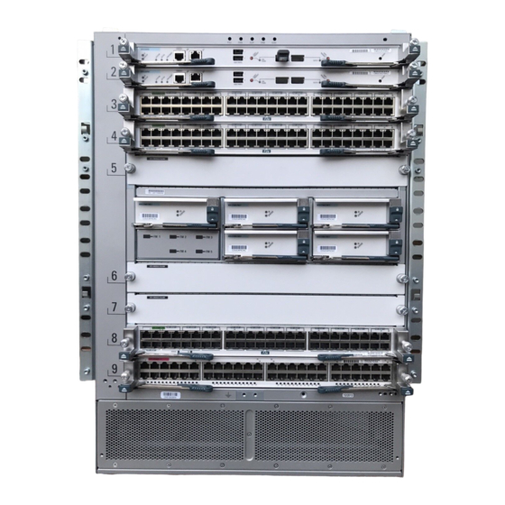
Cisco Nexus 7018 System The Cisco Nexus 7018 chassis has 18 slots that allow for two supervisor modules and up to 16 I/O modules. The chassis also holds up to five fabric modules, two fan trays, up to four power supply units, and a cable management system. - Page 31 S e n d d o c u m e n t c o m m e n t s t o n e x u s 7 k - d o c f e e d b a c k @ c i s c o . c o m Figure 1-8 Standard Hardware Features on the Front and Sides of the Cisco Nexus 7018 Chassis Cisco Nexus 7000 Series Hardware Installation and Reference Guide...
- Page 32 (N7K-M108X2-12L) Supervisor modules (1 or 2) in slots 9 and 10 Handles used to reposition the (N7K-SUP1) chassis (do not lift the chassis with these handles—use a mechanical lift) Cisco Nexus 7000 Series Hardware Installation and Reference Guide 1-12 OL-23069-06...
- Page 33 Cable Management System for the Cisco Nexus 7018 Chassis System status LEDs (these LEDs show the Upper cable management assemblies system status displayed by the chassis LEDs) Top hood Lower cable management assemblies Cisco Nexus 7000 Series Hardware Installation and Reference Guide 1-13 OL-23069-06...
- Page 34 S e n d d o c u m e n t c o m m e n t s t o n e x u s 7 k - d o c f e e d b a c k @ c i s c o . c o m Figure 1-10 Optional Front Door for the Cisco Nexus 7018 Chassis Front doors Air intake frame for power supply units Cisco Nexus 7000 Series Hardware Installation and Reference Guide 1-14 OL-23069-06...
- Page 35 S e n d d o c u m e n t c o m m e n t s t o n e x u s 7 k - d o c f e e d b a c k @ c i s c o . c o m Figure 1-11 Standard Hardware Features on the Back of the Cisco Nexus 7018 Chassis Cisco Nexus 7000 Series Hardware Installation and Reference Guide...
- Page 36 • chassis installation and 87.5 inches (222.2 cm). Install the Cisco Nexus 7018 chassis at the lowest possible RU on the rack for stability, as shown in Figure 1-12. If there is another device in the rack, install the heaviest one at the bottom.
-
Page 37: Preparing The Site
Installation of the equipment must comply with local and national electrical codes. Statement 1074 Warning Before you can install a Cisco Nexus 7000 Series system, you must prepare the site for the installation. You must make sure that the altitude, temperature, humidity, air quality, airflow, electromagnetic and radio frequency interference, floor structure, power, and earth grounding of the installation site all meet the requirements of the Cisco Nexus 7000 Series system that you are installing. -
Page 38: Safety Guidelines
19-inch EIA rack, and attach two bottom-support rails, you can begin installing the Cisco Nexus 7000 Series system. To install the system, you must load the chassis onto a mechanical lift, use the mechanical lift to position and elevate the chassis at its bottom-support rails on a rack or cabinet, push the chassis onto the rack or cabinet, and then secure the chassis to the rack or cabinet. -
Page 39: Managing The System Hardware
S e n d d o c u m e n t c o m m e n t s t o n e x u s 7 k - d o c f e e d b a c k @ c i s c o . c o m Managing the System Hardware After the Cisco Nexus 7000 Series system is installed and operating, you can use the Cisco NX-OS operating system to manage the system hardware. These management functions include displaying system and module information, setting the power supply modes, and managing module functions. - Page 40 S e n d d o c u m e n t c o m m e n t s t o n e x u s 7 k - d o c f e e d b a c k @ c i s c o . c o m Cisco Nexus 7000 Series Hardware Installation and Reference Guide...
-
Page 41: Preparing To Install The Switch
Unpacking and Inspecting a New Switch, page 2-3 • You must set up a two- or four-post, 19-inch EIA rack or cabinet before you can install the Cisco Nexus Note 7009 chassis. Make sure that you order the rack or cabinet and have it delivered before installing the chassis. -
Page 42: Required Tools
S e n d d o c u m e n t c o m m e n t s t o n e x u s 7 k - d o c f e e d b a c k @ c i s c o . c o m Required Tools Before you install the Cisco Nexus 7009 chassis into a rack, make sure that you have the following tools and equipment: Mechanical lift capable of lifting 300 pounds (136 kg) •... -
Page 43: Unpacking And Inspecting A New Switch
Unpacking and Inspecting a New Switch Before you install a new Cisco Nexus 7009 chassis, you need to unpack and inspect it to be sure that you have all the items that you ordered and verify that the switch was not damaged during shipment. If anything is damaged or missing, contact your customer representative immediately. -
Page 44: Installing The Bottom-Support Rails On The Rack
(without using bottom-support rails) and then fasten the upper chassis to the rack. This process enables you to install three 14-RU Cisco Nexus 7009 chassis in a 42-RU rack. If you do not need to install three chassis in a 42 RU rack, we recommend that you always install each chassis on bottom-support rails. -
Page 45: Prerequisites For Attaching The Bottom-Support Rails
To maximize the stability of the rack, install everything as low as possible on the rack with heavier items below lighter items. Be sure that there is 15 RU available for installing the Cisco Nexus 7009 chassis (14 RU) and its bottom-support rack (1 RU). Required Tools and Equipment You need the following tools and equipment to attach the bottom-support rails: •... - Page 46 Position one of the two front-mount bottom-support rails at the lowest possible RU on the rack. If you Step 1 are installing a chassis above another Cisco Nexus 7009 chassis, position the rail 26.25 inches (66.7 cm) (15 RU) above the bottom-support rails for the lower chassis as shown in Figure 2-1.
- Page 47 M6 x 19 mm or 12-24 x 3/4 in. Phillips screws on the front end of each bracket (using a total of 6 screws for both brackets) as shown in Figure 2-2. Cisco Nexus 7000 Series Hardware Installation and Reference Guide OL-23069-06...
-
Page 48: Attaching The Center-Mount Bottom-Support Rails
If you install a second chassis in the same rack, install it immediately above the lower system if there is enough vertical space. Cisco Nexus 7000 Series Hardware Installation and Reference Guide OL-23069-06... - Page 49 Position one of the two center-mount brackets at the lowest possible RU. If you are installing a chassis Step 1 above another Cisco Nexus 7009 chassis, position the rail 26.25 inches (66.7 cm) (15 RU) above the center-mount bottom-support rails for the lower chassis as shown in Figure 2-3.
- Page 50 Align the crossbar to the lower back of the two bottom-support rails and use two M4 x 8 mm screws to Step 3 attach it to each rail (one screw for each rail). Cisco Nexus 7000 Series Hardware Installation and Reference Guide 2-10 OL-23069-06...
-
Page 51: Installing The Chassis
Installing the Chassis This section describes how to install the Cisco Nexus 7009 chassis in a rack or cabinet. Depending on your data center requirements, you can choose to mount the front of the chassis to a rack or cabinet (standard method of mounting the chassis), or you can choose to mount the center of the chassis to a rack or cabinet. -
Page 52: Required Tools And Equipment
“Unpacking and Inspecting a New Switch” section on page 2-3. Required Tools and Equipment You need the following tools and equipment to install the Cisco Nexus 7009 chassis: Mechanical lift capable of lifting at least 300 pounds (136 kg) •... -
Page 53: Mounting The Chassis By Its Front Brackets
Center-mount bottom-support rails Center-mount bracket Mounting the Chassis by its Front Brackets To install a Cisco Nexus 7009 chassis by its front brackets to a rack or cabinet, follow these steps: Load the chassis onto a mechanical lift as follows: Step 1 Position the mechanical lift next to the shipping pallet that holds the chassis. - Page 54 S e n d d o c u m e n t c o m m e n t s t o n e x u s 7 k - d o c f e e d b a c k @ c i s c o . c o m Figure 2-5 Moving a Cisco Nexus 7009 Chassis onto a Rack (Front-Mount Installation) Push the lower half of the front side of the chassis 3...
-
Page 55: Mounting The Chassis By Its Center Brackets
Mounting the Chassis by its Center Brackets To install a Cisco Nexus 7009 chassis by its optional center bracket to a rack or cabinet, follow these steps: Follow these steps to replace the front-mount bracket on the chassis with center-mount brackets:... - Page 56 Remove the bracket from the chassis Position the center-mount bracket so that its five screw holes are aligned to the five screw holes used for the front-mount bracket (see Figure 2-8). Cisco Nexus 7000 Series Hardware Installation and Reference Guide 2-16 OL-23069-06...
- Page 57 Make sure that the front and rear of the chassis are unobstructed so you can easily push the chassis into the rack. Cisco Nexus 7000 Series Hardware Installation and Reference Guide 2-17...
- Page 58 (See Figure 2-9.) Figure 2-9 Moving a Cisco Nexus 7009 Chassis onto a Rack (Center-Mount Installation) Push the lower half of the front side of the chassis 3 Rack with vertical mount rails Center mount brackets...
-
Page 59: Grounding The Cisco Nexus 7009 Chassis
Grounding the Cisco Nexus 7009 Chassis If you are using AC power supply units, the Cisco Nexus 7009 system is grounded through the AC power supply cables and one of two grounding connections on the chassis. The AC power supply cables provide a connection to an earth ground whenever you connect the AC power to the system. -
Page 60: Prerequisites For Grounding The Chassis
Before you can ground the chassis, you must have a connection to the earth ground for the data center building. If you installed the Cisco Nexus 7009 chassis into a bonded rack (see the rack manufacturer’s instructions for more information) that now has a connection to the data center earth ground, you can ground the chassis by connecting its grounding ports to the rack. - Page 61 Ensure that the grounding lug and the grounding wire do not interfere with other switch hardware or rack equipment. Cisco Nexus 7000 Series Hardware Installation and Reference Guide 2-21 OL-23069-06...
- Page 62 S e n d d o c u m e n t c o m m e n t s t o n e x u s 7 k - d o c f e e d b a c k @ c i s c o . c o m Figure 2-12 Grounding Pad on the Front of the Cisco Nexus 7009 Chassis Grounding pad Prepare the other end of the grounding wire and connect it to an appropriate grounding point in your site to ensure an adequate earth ground for the switch.
-
Page 63: Connecting Your Esd Wrist Strap To The Chassis
After you connect the chassis to the data center earth ground, you can ground your ESD wrist strap by plugging it into an ESD port (shown in Figure 2-13). Figure 2-13 ESD Grounding Port on the Front of the Cisco Nexus 7009 Chassis ESD grounding port Cisco Nexus 7000 Series Hardware Installation and Reference Guide 2-23 OL-23069-06... -
Page 64: Installing The Cable Management Frames
S e n d d o c u m e n t c o m m e n t s t o n e x u s 7 k - d o c f e e d b a c k @ c i s c o . c o m Installing the Cable Management Frames After you have fully installed the Cisco Nexus 7009 switch chassis in the rack or cabinet (see the “Installing the Chassis” section on page 2-11), you can install the cable management frames on the front of the chassis. - Page 65 Push the top hood toward the chassis so that its alignment pins enter the alignment holes and the top hood rests against the chassis as shown in Figure 2-15. Cisco Nexus 7000 Series Hardware Installation and Reference Guide 2-25 OL-23069-06...
- Page 66 Fastening the Top Hood to the Chassis and Cable Management Assemblies Four M4x8 pan-head screws that fasten the top hood to the left and right cable management assemblies (two screws for each side). Cisco Nexus 7000 Series Hardware Installation and Reference Guide 2-26 OL-23069-06...
-
Page 67: Installing The Front Door And Air Intake Frame
If you need to install the optional double-hinged door and air intake frame, you must install them after installing the cable management frame on the chassis. To install the front door and air intake frame to the Cisco Nexus 7009 cable management system, follow these steps:... - Page 68 Assemble the two pieces of the right door stop over the bushings and post. Fasten the two pieces together Step 3 with two M4 flathead screws (see Figure 2-19). Cisco Nexus 7000 Series Hardware Installation and Reference Guide 2-28 OL-23069-06...
- Page 69 2-20. Push the hinge bracket to the chassis so that the pins go into the chassis. Two screw holes in each of the cable management side frames should align to screw holes in the hinge bracket. Cisco Nexus 7000 Series Hardware Installation and Reference Guide 2-29 OL-23069-06...
- Page 70 Positioning the Hinge Bracket to the Cable Management Frames and Chassis Alignment pins Alignment holes Step 5 Attach the bracket to the chassis and cable management frames with eight loosely fastened M4x8 screws, as shown in Figure 2-21. Cisco Nexus 7000 Series Hardware Installation and Reference Guide 2-30 OL-23069-06...
- Page 71 Align the two captive screws on the air intake frame to the two screw holes below the cable management Step 8 frames on the chassis as shown in Figure 2-22. Cisco Nexus 7000 Series Hardware Installation and Reference Guide 2-31 OL-23069-06...
- Page 72 The double-hinge door can be installed and opened on either side. The figures in this procedure show Note how to install the door on the left side first, but you can use the instructions to install it on either side. Cisco Nexus 7000 Series Hardware Installation and Reference Guide 2-32 OL-23069-06...
- Page 73 2-24. This action locks the latches around the hinge pins so that you no longer need to hold the door onto the chassis. Figure 2-24 Attaching the Left Side of the Door Cisco Nexus 7000 Series Hardware Installation and Reference Guide 2-33 OL-23069-06...
- Page 74 See Figure 2-25. Figure 2-25 Attaching the Right Side of the Door Door handle pulled out until it clicks Door closed onto the hinge pins Hinge pins Cisco Nexus 7000 Series Hardware Installation and Reference Guide 2-34 OL-23069-06...
-
Page 75: Installing And Formatting Compactflash Cards
Installing and Formatting CompactFlash Cards Each supervisor module on a Cisco Nexus 7000 Series switch is shipped with a CompactFlash card installed in the LOG FLASH reader. The EXPANSION FLASH reader is left empty, but you can optionally install a card in that reader. - Page 76 Make sure that the card is fully inserted inside the reader. If the card is fully inserted, either format the card (see the Cisco Nexus 7000 Series NX-OS Fundamentals Configuration Guide) or replace the card with another card that is properly formatted for the reader (see the “Replacing a...
-
Page 77: Installing A Cisco Nexus 7010 Chassis
C H A P T E R Installing a Cisco Nexus 7010 Chassis This chapter describes how to install a new or relocated Cisco Nexus 7010 chassis in a rack or cabinet. For information about installing a Cisco Nexus 7009 chassis, see Chapter 2, “Installing a Cisco Nexus... -
Page 78: Installing A Four-Post Rack Or Cabinet
Before you install the Cisco Nexus 7010 chassis, you must install a standard four-post, 19-inch EIA data center rack (or a cabinet that contains such a rack) that meets the requirements listed in the Cisco Nexus 7000 Series Site Preparation Guide. To maximize safety, you should do the following for the rack: Bolt the rack to the concrete subfloor before moving the Cisco Nexus 7010 chassis onto it. -
Page 79: Unpacking And Inspecting A New Switch
Unpacking and Inspecting a New Switch Before you install a new Cisco Nexus 7010 chassis, you need to unpack and inspect it to be sure that you have all the items that you ordered and verify that the switch was not damaged during shipment. If anything is damaged or missing, contact your customer representative immediately. -
Page 80: Prerequisites For Attaching The Bottom-Support Rails
Before you can attach the bottom-support rails, you must fully install the rack or cabinet, and should, for maximum stability, bolt the rack or cabinet to the concrete subfloor. If anything lighter than the Cisco Nexus 7010 system is already installed in the rack, you should make sure that it is positioned above where you will be installing the Cisco Nexus 7010 system. - Page 81 Position one of the two adjustable bottom-support rails at the lowest possible RU. If you are installing a Step 1 chassis above another Cisco Nexus 7010 chassis, position the rail 36.75 inches (93.4 cm) (21 RU) above the bottom-support rails for the lower chassis as shown in Figure 3-1.
- Page 82 Three of the screw holes on each end of the bottom-support rail align to the screw holes in the mounting Note rail. Use a screw in each of these screw holes. Cisco Nexus 7000 Series Hardware Installation and Reference Guide OL-23069-06...
-
Page 83: Installing The Chassis
3 12-24 x 3/4 in. Phillips screws Installing the Chassis This section describes how to install the Cisco Nexus 7010 chassis in a rack or cabinet. These installation steps include transporting the chassis, elevating the chassis to the rack using a mechanical lift, pushing the chassis onto the rack, and then securing the chassis to the rack. -
Page 84: Required Tools And Equipment
“Unpacking and Inspecting a New Switch” section on page 3-3. Required Tools and Equipment You need the following tools and equipment to install the Cisco Nexus 7010 chassis: • Mechanical lift capable of lifting at least 550 pounds (250 kg) You must use a mechanical lift whenever lifting a device over 120 pounds (55 kg). -
Page 85: Installing The Chassis
Note kg), onto and off the mechanical lift and rack. Installing the Chassis To install a Cisco Nexus 7010 chassis in a four-post rack or cabinet, follow these steps: Load the chassis onto a mechanical lift as follows: Step 1 Position the mechanical lift next to the shipping pallet that holds the chassis. - Page 86 Use a Phillips screwdriver to screw in four M6 x 19-mm or 12-24 x 3/4-inch screws in each of the two Step 5 chassis mounting brackets (use a total of eight screws for two mounting brackets) as shown in Figure 3-4. Cisco Nexus 7000 Series Hardware Installation and Reference Guide 3-10 OL-23069-06...
-
Page 87: Grounding The Cisco Nexus 7010 Chassis
Grounding the Cisco Nexus 7010 Chassis The Cisco Nexus 7010 system is grounded through the AC power supply cables and one of two grounding connections on the chassis. The AC power supply cables provide a connection to an earth ground whenever you connect the AC power to the system. -
Page 88: Prerequisites For Grounding The Chassis
Before you can ground the chassis, you must have a connection to the earth ground for the data center building. If you installed the Cisco Nexus 7010 chassis into a bonded rack (see the rack manufacturer’s instructions for more information) that now has a connection to the data center earth ground, you can ground the chassis by connecting its grounding ports to the rack. - Page 89 Figure 3-6 Grounding Pad on the Front of the Cisco Nexus 7010 Chassis Grounding pad Cisco Nexus 7000 Series Hardware Installation and Reference Guide...
-
Page 90: Connecting Your Esd Wrist Strap To The Chassis
S e n d d o c u m e n t c o m m e n t s t o n e x u s 7 k - d o c f e e d b a c k @ c i s c o . c o m Figure 3-7 Grounding Pad on the Rear of the Cisco Nexus 7010 Chassis Grounding pad... - Page 91 S e n d d o c u m e n t c o m m e n t s t o n e x u s 7 k - d o c f e e d b a c k @ c i s c o . c o m Figure 3-8 ESD Grounding Ports on the Front of the Cisco Nexus 7010 Chassis ESD grounding port...
-
Page 92: Installing And Formatting Compactflash Cards
ESD grounding port Installing and Formatting CompactFlash Cards Each supervisor module on a Cisco Nexus 7000 Series switch is shipped with a CompactFlash card installed in the LOG FLASH reader. The EXPANSION FLASH reader is left empty, but you can optionally install a card in that reader. -
Page 93: Installing The Front Doors And Frame Assembly
Make sure that the card is fully inserted inside the reader. If the card is fully inserted, either format the card (see the Cisco Nexus 7000 Series NX-OS Fundamentals Configuration Guide) or replace the card with another card that is properly formatted for the reader (see the “Replacing a... - Page 94 For each of the two front doors, match the two alignment pins on the door frame to the alignment holes on the chassis. Position each door frame immediately under the cable management area (see Figure 3-12). Cisco Nexus 7000 Series Hardware Installation and Reference Guide 3-18 OL-23069-06...
- Page 95 Place door frame on front edge of chassis and immediately under the cable management area. Cable management area. Tighten three screws for each door frame (see Figure 3-13). Step 3 Cisco Nexus 7000 Series Hardware Installation and Reference Guide 3-19 OL-23069-06...
- Page 96 Remove the EMI panel by unscrewing its four captive screws until each is free of the chassis (see Figure 3-14). Cisco Nexus 7000 Series Hardware Installation and Reference Guide 3-20 OL-23069-06...
- Page 97 EMI panel. Screw in a screw in each of these two screw holes so that the side frame assembly is attached to the EMI panel. Repeat this step for the other side of the EMI panel. See Figure 3-15. Cisco Nexus 7000 Series Hardware Installation and Reference Guide 3-21 OL-23069-06...
- Page 98 Realign the EMI panel to the air intake area on the chassis, screw its four captive screws to the chassis, and tighten the captive screws to 8 in-lb (0.9 N·m). Cisco Nexus 7000 Series Hardware Installation and Reference Guide 3-22...
-
Page 99: Installing The Air Filter
S e n d d o c u m e n t c o m m e n t s t o n e x u s 7 k - d o c f e e d b a c k @ c i s c o . c o m Installing the Air Filter You can install the optional air filter while the Cisco Nexus 7000 Series system is operational. Note Only the Cisco Nexus 7010 switch includes an optional air filter. - Page 100 S e n d d o c u m e n t c o m m e n t s t o n e x u s 7 k - d o c f e e d b a c k @ c i s c o . c o m Cisco Nexus 7000 Series Hardware Installation and Reference Guide...
-
Page 101: Installing A Cisco Nexus 7018 Chassis
C H A P T E R Installing a Cisco Nexus 7018 Chassis This chapter describes how to install a new or relocated Cisco Nexus 7018 chassis in a rack or cabinet. For information about installing a Cisco Nexus 7009 chassis, see Chapter 2, “Installing a Cisco Nexus... -
Page 102: Installing A Four-Post Rack Or Cabinet
Before you install the switch, you must install a standard four-post, 19-inch EIA data center rack (or in a cabinet that contains such a rack) that meets the requirements listed in the Cisco Nexus 7000 Series Site Preparation Guide. To maximize safety, you should do the following for the rack: Bolt the rack to the concrete subfloor before moving the Cisco Nexus 7018 chassis onto it. -
Page 103: Unpacking And Inspecting A New Chassis
Unpacking and Inspecting a New Chassis Before you install a new Cisco Nexus 7018 chassis, you need to unpack and inspect it to be sure that you have all the items that you ordered and verify that the switch was not damaged during shipment. If anything is damaged or missing, contact your customer representative immediately. -
Page 104: Prerequisites For Attaching The Bottom-Support Rails
Before you can attach the bottom-support rails, you must fully install the rack or cabinet, and should, for maximum stability, bolt the rack or cabinet to the concrete subfloor. If anything lighter than the Cisco Nexus 7018 system is already installed in the rack, you should make sure that it is positioned above where you will be installing the Cisco Nexus 7000 Series system. - Page 105 Note Make sure that the two bottom-support rails are level with one another. If they are not level, adjust the higher rail down to the level of the lower rail. Cisco Nexus 7000 Series Hardware Installation and Reference Guide OL-23069-06...
- Page 106 Use a Phillips screwdriver to screw in at least three (four if possible) M6 x 19 mm or 12-24 x 3/4 inch Phillips screws on each end of each rail (using a total of 16 screws for both brackets) as shown in Figure 4-2. Cisco Nexus 7000 Series Hardware Installation and Reference Guide OL-23069-06...
-
Page 107: Installing The Chassis
Before you install the chassis, you must make sure that the following items are available for the installation: Data center ground is accessible where you are installing the Cisco Nexus 7018 chassis. • Four-post, 19-inch EIA rack or cabinet that includes such a rack. -
Page 108: Required Tools And Equipment
“Unpacking and Inspecting a New Chassis” section on page 4-3. Required Tools and Equipment You need the following tools and equipment to install the Cisco Nexus 7000 Series chassis: • Mechanical lift capable of lifting at least 700 pounds (318 kg) You must use a mechanical lift to lift a switch weighing over 120 pounds (55 kg). -
Page 109: Installing The Chassis
Note kg), onto and off the mechanical lift and rack. Installing the Chassis To install a Cisco Nexus 7018 chassis in a four-post rack or cabinet, follow these steps: Load the chassis onto a mechanical lift as follows: Step 1 Position the mechanical lift next to the shipping pallet that holds the chassis. - Page 110 Use a Phillips screwdriver to screw in nine M6 x 19-mm or 12-24 x 3/4-inch screws in each of the two Step 5 chassis mounting brackets (use a total of 18 screws for two mounting brackets) as shown in Figure 4-4. Cisco Nexus 7000 Series Hardware Installation and Reference Guide 4-10 OL-23069-06...
- Page 111 Nine M6 x 19 mm or 10-24 x 3/4 in. Phillips screws used to attach each side bracket to a front mounting rail (use a total of 18 screws) Cisco Nexus 7000 Series Hardware Installation and Reference Guide 4-11 OL-23069-06...
-
Page 112: Grounding The Cisco Nexus 7018 Chassis
S e n d d o c u m e n t c o m m e n t s t o n e x u s 7 k - d o c f e e d b a c k @ c i s c o . c o m Grounding the Cisco Nexus 7018 Chassis The Cisco Nexus 7018 system is grounded through the AC power supply cables and one of two grounding connections on the chassis. The AC power supply cables provide a connection to an earth ground whenever you connect the AC power to the system. -
Page 113: Connecting The System Ground
Ensure that the grounding lug and the grounding wire do not interfere with other switch hardware or rack equipment. Cisco Nexus 7000 Series Hardware Installation and Reference Guide 4-13 OL-23069-06... -
Page 114: Connecting Your Esd Wrist Strap To The Chassis
Connecting Your ESD Wrist Strap to the Chassis After you connect the chassis to the earth ground, you can ground your ESD wrist strap by plugging it into the ESD port shown in Figure 4-7. Cisco Nexus 7000 Series Hardware Installation and Reference Guide 4-14 OL-23069-06... -
Page 115: Installing The Cable Management Frame
ESD grounding port Installing the Cable Management Frame After you have fully installed the Cisco Nexus 7018 switch chassis in the rack or cabinet (see the “Installing the Chassis” section on page 4-7), you can install the cable management frame on the front of the chassis. - Page 116 Attach a lower cable management assembly (800-31343-01) onto the two hooks that protrude from the Step 1 lower half of the left rack-mount bracket that is attached to the Cisco Nexus 7018 switch chassis, and loosely fasten the assembly to the chassis with four flat-head M4x10 screws as shown in Figure 4-8.
- Page 117 Attach an upper cable management assembly (800-31342-01) onto the two hooks that protrude from the Step 3 upper half of the left rack-mount bracket that is attached to the Cisco Nexus 7018 switch chassis, and loosely fasten the assembly to the chassis with four flat-head M4x10 screws as shown in Figure 4-9.
- Page 118 Figure 4-11. Push the top hood toward the chassis so that its alignment pins enter the alignment holes and the top hood rests against the chassis. Cisco Nexus 7000 Series Hardware Installation and Reference Guide 4-18 OL-23069-06...
- Page 119 Positioning the Top Hood with the Upper Cable Management Assemblies and the Switch Chassis Alignment pins Alignment holes Use four M4x8 pan-head screws to loosely fasten the top hood to the chassis as shown in Figure 4-12. Step 6 Cisco Nexus 7000 Series Hardware Installation and Reference Guide 4-19 OL-23069-06...
-
Page 120: Installing The Front Door And Air Intake Frame
Also, make sure that the cable management frame is aligned to the vertical sides of the chassis and that the cable management hood is level when you install those components. Cisco Nexus 7000 Series Hardware Installation and Reference Guide 4-20... - Page 121 S e n d d o c u m e n t c o m m e n t s t o n e x u s 7 k - d o c f e e d b a c k @ c i s c o . c o m To install the front door and air intake frame to the Cisco Nexus 7018 cable management system, follow...
- Page 122 Step 3 Position the hinge bracket (700-28491-01) at the bottom of the cable management frame and the chassis as shown in Figure 4-15. Cisco Nexus 7000 Series Hardware Installation and Reference Guide 4-22 OL-23069-06...
- Page 123 Positioning the Hinge Bracket to the Cable Management Frame and Chassis Alignment pins Alignment holes Step 4 Attach the bracket to the chassis with eight loosely fastened M4x8 screws, as shown in Figure 4-16. Cisco Nexus 7000 Series Hardware Installation and Reference Guide 4-23 OL-23069-06...
- Page 124 Fasten the four ball-point studs (51-5008-01), each one with a washer (49-0430-01), to the bottom portion of the chassis, one stud by each corner of the air intake area as shown in Figure 4-17. Cisco Nexus 7000 Series Hardware Installation and Reference Guide 4-24 OL-23069-06...
- Page 125 Align the air intake frame to the four ball-point studs and press the frame onto the chassis as shown in Step 8 Figure 4-18. The captive screws on the air-intake frame should align with their screw holes in the chassis. Cisco Nexus 7000 Series Hardware Installation and Reference Guide 4-25 OL-23069-06...
- Page 126 The double-hinge door can be installed and opened on either side. The figures in this procedure show Note how to install the door on the left side first, but you can use the instructions to install it on either side. Cisco Nexus 7000 Series Hardware Installation and Reference Guide 4-26 OL-23069-06...
- Page 127 See Figure 4-20. This action locks the latches around the hinge pins so that you no longer need to hold the door onto the chassis. Cisco Nexus 7000 Series Hardware Installation and Reference Guide 4-27 OL-23069-06...
- Page 128 Open the door handle on the open side of the door until it clicks. This action opens the latches on the Step 13 open side of the door. See Figure 4-21. Cisco Nexus 7000 Series Hardware Installation and Reference Guide 4-28 OL-23069-06...
- Page 129 If you do not hear the latches click, press the door at the handle to fully close it and to activate the latches. Test the door to make sure that it is fully secured to the four hinge pins. Cisco Nexus 7000 Series Hardware Installation and Reference Guide 4-29...
-
Page 130: Installing And Formatting Compactflash Cards
Installing and Formatting CompactFlash Cards Each supervisor module on a Cisco Nexus 7018 system is shipped with a CompactFlash card installed in the LOG FLASH reader. The EXPANSION FLASH reader is left empty, but you can optionally install a card in that reader. - Page 131 Make sure that the card is fully inserted inside the reader. If the card is fully inserted, either format the card (see the Cisco NX-OS Fundamentals Configuration Guide) or replace the card with another card that is properly formatted for the reader (see the “Replacing a CompactFlash Card”...
- Page 132 S e n d d o c u m e n t c o m m e n t s t o n e x u s 7 k - d o c f e e d b a c k @ c i s c o . c o m Cisco Nexus 7000 Series Hardware Installation and Reference Guide...
-
Page 133: Chapter 5 Installing Power Supply Units
Installing Power Supply Units You can install up to two power supply units in the Cisco Nexus 7009 chassis, up to three power supply units in the Cisco Nexus 7010 chassis, and up to four power supply units in the Cisco Nexus 7018 chassis. -
Page 134: Connecting An Ac Power Supply Unit To Ac Power Sources
Connecting an AC Power Supply Unit to AC Power Sources If you are powering your Cisco Nexus 7000 Series switch with 6-kW or 7.5-kW AC power supply units, you must connect those power supply units to an AC power source. When you connect the power cable to the AC power grid and the power supply unit, the unit is automatically grounded through this interface. -
Page 135: Prerequisites For Connecting Ac Power Supply Units To Ac Power Sources
20-A circuit. If you are using the input source redundancy mode, you must connect each power cable to separate 20-A circuits. Warning Take care when connecting units to the supply circuit so that wiring is not overloaded. Statement 1018 Cisco Nexus 7000 Series Hardware Installation and Reference Guide OL-23069-06... -
Page 136: Connecting A 7.5-Kw Ac Power Supply Unit To Ac Power Sources
LEDs are lit and the FAULT LED is not lit or blinking. For an explanation of all the power supply unit LEDs and the conditions that they indicate, see Table D-5 on page D-5. Cisco Nexus 7000 Series Hardware Installation and Reference Guide OL-23069-06... -
Page 137: Connecting A Dc Power Supply Unit To Dc Power Sources
Grounding a 6-kW DC Power Supply Unit After you have mounted a 6-kW DC power supply unit in a Cisco Nexus 7000 Series chassis, you must ground the power supply unit to the earth ground before connecting it to the DC power source. You ground this power supply unit by connecting the grounding pad on the lower front side of the power supply unit to the earth ground. -
Page 138: Required Tools And Equipment
Ensure that the grounding lug and the grounding wire do not interfere with other switch hardware or rack equipment. Cisco Nexus 7000 Series Hardware Installation and Reference Guide OL-23069-06... -
Page 139: Connecting A Dc Power Supply Unit Directly To Dc Power Sources
Installation of the equipment must comply with local and national electrical codes. Statement 1074 When installing or replacing the unit, the ground connection must always be made first and Warning disconnected last. Statement 1046 Cisco Nexus 7000 Series Hardware Installation and Reference Guide OL-23069-06... - Page 140 Connecting DC Power to a 6-kW DC Power Supply Unit DC power grid DC power supply unit Isolated inputs from DC power grid Two plugs, each with two isolated inputs from the DC power grid Cisco Nexus 7000 Series Hardware Installation and Reference Guide OL-23069-06...
- Page 141 The power cables required for each DC power supply unit are shipped with the DC power supply unit. Note If you do not have the correct cables, contact Cisco TAC. Read the installation instructions before connecting the system to the power source. Statement 1004...
- Page 142 Be sure uninsulated conductors are not accessible when cover is in place. Statement 1075 Connect one or two power cables (Cisco part number N7K-DC-CAB=) to the DC power supply unit and Step 4 the DC power grid. Each cable has one plug that connects two fully isolated 1.5 kW input modules to a DC power supply for 3 kW of power.
-
Page 143: Connecting A Power Supply Unit To Dc Power Sources Though A Power Interface Unit
Figure 5-6 Connecting DC Power to a 3-kW DC Power Supply Unit DC power grid DC power supply unit Isolated inputs from DC power grid Plug with two isolated inputs Cisco Nexus 7000 Series Hardware Installation and Reference Guide 5-11 OL-23069-06... - Page 144 Connecting DC Power to a 3-kW DC Power Supply Unit with 3-kW Power Redundancy Separate DC power grids DC power supply unit Isolated inputs from DC power grid Two plugs, each with two isolated inputs from separate DC power grids Cisco Nexus 7000 Series Hardware Installation and Reference Guide 5-12 OL-23069-06...
-
Page 145: Required Tools And Equipment
Installing the PIU in a Rack To install a PIU in a rack, follow these steps: Position and fasten the two mounting brackets in one of four ways shown in Figure 5-9. Step 1 Cisco Nexus 7000 Series Hardware Installation and Reference Guide 5-13 OL-23069-06... - Page 146 Fasten the PIU to the rack using four M6 x 19 mm screws or four 12-24 x 3/4 inch screws, as shown in Figure 5-10. Tighten each screw to 40 in-lb (4.5 N·m). Cisco Nexus 7000 Series Hardware Installation and Reference Guide 5-14 OL-23069-06...
- Page 147 40 in-lb (4.5 N·m). Figure 5-11 shows the location of the grounding pads on the PIU. Ensure that the grounding lug and the grounding wire do not interfere with other PIU equipment. Cisco Nexus 7000 Series Hardware Installation and Reference Guide 5-15 OL-23069-06...
- Page 148 The power cables required for each DC power supply unit are shipped with the DC power supply unit. Note If you do not have the correct cables, contact Cisco TAC. Read the installation instructions before connecting the system to the power source. Statement 1004...
- Page 149 Be sure uninsulated conductors are not accessible when cover is in place. Statement 1075 Insert the plug end of one or two power cables (Cisco part number N7K-DC-CAB=) to the power Step 4 receptacles on the DC power supply unit as follows: For 3-kW output power, connect one power cable to the power supply unit.
- Page 150 For each power cable coming from a power source, connect it to the PIU as follows: Step 9 Attach two negative input lugs to the negative posts on the rear side of the PIU (see callout 1 in Figure 5-13). Cisco Nexus 7000 Series Hardware Installation and Reference Guide 5-18 OL-23069-06...
- Page 151 If you are outputting 6 kW of power, the Input 1, Input 2, Input 3, and Input 4 LEDs will turn green. • If the FAULT LED is lit or blinking, call Cisco TAC for assistance. Cisco Nexus 7000 Series Hardware Installation and Reference Guide...
- Page 152 S e n d d o c u m e n t c o m m e n t s t o n e x u s 7 k - d o c f e e d b a c k @ c i s c o . c o m Cisco Nexus 7000 Series Hardware Installation and Reference Guide...
-
Page 153: Connecting The Cisco Nexus 7000 Series Switch To The Network
Connecting the Cisco Nexus 7000 Series Switch to the Network This chapter describes how to connect the Cisco Nexus 7000 Series switch (configure its IP address through a console, set up its management interface, and connect its Ethernet ports to the network) after it has been installed in its rack or cabinet. -
Page 154: Connecting To The Console
COM1/AUX SERIAL PORT—Use this port if you are using a modem. • You can find this cable in the console cable connector kit, which is part of the accessory kit for the Cisco Nexus 7000 Series switch. Cisco Nexus 7000 Series Hardware Installation and Reference Guide... -
Page 155: Creating An Initial Switch Configuration
IP address. You can perform the other configurations at a later time as described in the Cisco Nexus 7000 Series NX-OS Fundamentals Configuration Guide, Release 6.x. Before you perform the initial switch configuration, you must determine the IP address and netmask... -
Page 156: Setting Up The Management Interface
The software asks if you need to save the configuration. Step 8 Enter yes to save the configuration. You can now set up the management interface for each supervisor module on the Cisco Nexus 7000 Series switch. Setting Up the Management Interface... -
Page 157: Connecting The Supervisor Cmp Port
Step 3 Connecting the Supervisor CMP Port The CMP, which is included on the Cisco Nexus 7000 Series supervisor module, is a secondary, lightweight processor that provides a second network interface to the system for use even when the Control Processor (CP) is not reachable. You can access the CMP to perform operations, such as taking over the CP console, restarting the CP, or restarting a particular I/O module. - Page 158 Chapter 6 Connecting the Cisco Nexus 7000 Series Switch to the Network Connecting an I/O Module S e n d d o c u m e n t c o m m e n t s t o n e x u s 7 k - d o c f e e d b a c k @ c i s c o . c o m...
- Page 159 Chapter 6 Connecting the Cisco Nexus 7000 Series Switch to the Network Connecting an I/O Module S e n d d o c u m e n t c o m m e n t s t o n e x u s 7 k - d o c f e e d b a c k @ c i s c o . c o m...
-
Page 160: Connecting Or Disconnecting A 1000Base-T Port
Chapter 6 Connecting the Cisco Nexus 7000 Series Switch to the Network Connecting an I/O Module S e n d d o c u m e n t c o m m e n t s t o n e x u s 7 k - d o c f e e d b a c k @ c i s c o . c o m... -
Page 161: Disconnecting A 1000Base-T Port From The Network
Chapter 6 Connecting the Cisco Nexus 7000 Series Switch to the Network Connecting an I/O Module S e n d d o c u m e n t c o m m e n t s t o n e x u s 7 k - d o c f e e d b a c k @ c i s c o . c o m To connect a 1000BASE-T Ethernet port to the network, follow these steps: Attach an ESD-preventative wrist strap and follow its instructions for use. -
Page 162: Installing A Transceiver
Insert a dust cover into the port end of the transceiver and place the transceiver on an antistatic mat or Step 4 into a static shielding bag if you plan to return it to your Cisco representative. If another transceiver is not being installed, protect the optical port cage by inserting a clean cover. -
Page 163: Connecting A Fiber-Optic Cable To A Transceiver
Chapter 6 Connecting the Cisco Nexus 7000 Series Switch to the Network Connecting an I/O Module S e n d d o c u m e n t c o m m e n t s t o n e x u s 7 k - d o c f e e d b a c k @ c i s c o . c o m... -
Page 164: Maintaining Transceivers And Fiber-Optic Cables
Chapter 6 Connecting the Cisco Nexus 7000 Series Switch to the Network Connecting an I/O Module S e n d d o c u m e n t c o m m e n t s t o n e x u s 7 k - d o c f e e d b a c k @ c i s c o . c o m... -
Page 165: Displaying The Switch Hardware Inventory
Displaying the Switch Hardware Inventory You can display information about the field replaceable units (FRUs), including product IDs, serial numbers, and version IDs by entering the show inventory command. See Example 7-1. Cisco Nexus 7000 Series Hardware Installation and Reference Guide OL-23069-06... - Page 166 DESCR: "Nexus7000 C7009 (9 Slot) Chassis Fan Module" PID: N7K-C7009-FAN VID: V00 , SN: JAF1433DDEJ switch# To display switch hardware inventory details, enter the show hardware command. See Example 7-2. Cisco Nexus 7000 Series Hardware Installation and Reference Guide OL-23069-06...
-
Page 167: Chapter 7 Managing The Switch Hardware
MAC address is 00-24-98-e8-20-00 CMP (Module 6) ok Hardware Freescale Inc mpc8343 (rev 3.1 (pvr 8083 0031)) CPU with 128 MB of memory Model number is N7K-SUP1 H/W Version is 1.2 Cisco Nexus 7000 Series Hardware Installation and Reference Guide OL-23069-06... - Page 168 Manufacture Date is Year 13 Week 9 Serial number is JAF1309ABLE CLEI code is COUIAW3CAA Module5 Module type is : Supervisor module-1X 0 submodules are present Model number is N7K-SUP1 H/W version is 1.2 Cisco Nexus 7000 Series Hardware Installation and Reference Guide OL-23069-06...
- Page 169 Model number is N7K-C7010-FAB-1 H/W version is 1.0 Part Number is 73-10624-04 Part Revision is C0 Manufacture Date is Year 13 Week 9 Serial number is JAF1309AAHB CLEI code is COUCAGVCAA Cisco Nexus 7000 Series Hardware Installation and Reference Guide OL-23069-06...
- Page 170 Serial number is DTH1217T029 CLEI code is IPUPADBAAA PS3 ok Power supply type is: 6000.00W 220v AC Model number is N7K-AC-6.0KW H/W version is 1.0 Part Number is 341-0230-02 Part Revision is A0 Cisco Nexus 7000 Series Hardware Installation and Reference Guide OL-23069-06...
-
Page 171: Displaying The Switch Serial Number
E x a m p l e 7 - 3 Example 7-3 Displaying the Switch Serial Number switch# show sprom backplane 1 DISPLAY backplane sprom contents: Common block: Block Signature : 0xabab Block Version Block Length : 160 Cisco Nexus 7000 Series Hardware Installation and Reference Guide OL-23069-06... - Page 172 00 00 00 00 00 00 00 00 00 00 00 00 00 00 00 00 00 00 00 00 00 00 00 00 00 00 00 00 00 00 00 00 Cisco Nexus 7000 Series Hardware Installation and Reference Guide OL-23069-06...
-
Page 173: Displaying Power Usage Information
N7K-M148GT-11 400 W Powered-Up N7K-SUP1 210 W Powered-Up N7K-SUP1 210 W Powered-Up N7K-M132XP-12 750 W Powered-Up N7K-M148GS-11 284 W 400 W Powered-Up N7K-C7010-FAB-1 60 W Powered-Up N7K-C7010-FAB-1 60 W Powered-Up Cisco Nexus 7000 Series Hardware Installation and Reference Guide OL-23069-06... -
Page 174: Power Supply Configuration Modes
( 1 . 2 k W + 1 . 2 k W + 1 . 2 k W ) a n d t h e r e s e r v e p o w e r w o u l d b e 9 . 0 k W ( 3 . 0 k W + 3 . 0 k W + 3 . 0 k W ) . Cisco Nexus 7000 Series Hardware Installation and Reference Guide... - Page 175 1 power supply unit 1200 W — — — 2 power supply units 2400 W 1200 W — — 3 power supply units 3600 W 2400 W — — Cisco Nexus 7000 Series Hardware Installation and Reference Guide 7-11 OL-23069-06...
-
Page 176: Configuring The Power Supply Mode
4 power supply units 15,000 W 11,250 W — — Configuring the Power Supply Mode You can configure the power supply mode. SUMMARY STEPS config t power redundancy-mode mode Cisco Nexus 7000 Series Hardware Installation and Reference Guide 7-12 OL-23069-06... -
Page 177: Power Supply Configuration Guidelines
9.0 kW. The increased amount of available power exceeds the switch power requirement, so all of the modules and fan trays in the switch can power up. Table 7-3 shows the results for each scenario. Cisco Nexus 7000 Series Hardware Installation and Reference Guide 7-13 OL-23069-06... - Page 178 (kW) Result — 8.784 — The available power does not meet the system usage requirement, so you cannot power the entire system with this power supply configuration and mode. Cisco Nexus 7000 Series Hardware Installation and Reference Guide 7-14 OL-23069-06...
- Page 179 The available power exceeds the switch usage requirement, so you can power up all of the modules and fan trays in the switch. Table 7-5 shows the results for each scenario. Cisco Nexus 7000 Series Hardware Installation and Reference Guide 7-15 OL-23069-06...
- Page 180 The available power meets the switch usage requirements, so you can power up the entire switch. Table 7-6 shows the results for each scenario. Cisco Nexus 7000 Series Hardware Installation and Reference Guide 7-16 OL-23069-06...
-
Page 181: Information About Modules
• Supervisor Modules The Cisco Nexus 7010 switch has one or two supervisor modules (N7K-SUP-1). When it has two supervisors, one supervisor is automatically active while the other is in standby mode. If the active supervisor goes down or is disconnected for replacement, the standby supervisor automatically becomes active. - Page 182 Relative usage If you are logged into the active supervisor (in any Cisco Nexus 7000 sup-local and sup-remote Series chassis), the following applies: sup-local refers to the active supervisor module.
-
Page 183: I/O Modules
• fabric modules. You can replace a Series 1 fabric module with a Series 2 module in the Cisco Nexus 7010 and 7018 Note switches during operations, but while there is a mix of fabric module types, all of the fabric modules perform as Series 1 fabric modules. -
Page 184: Checking The State Of A Module
Status column each time. The I/O module goes through a testing and an initializing stage before displaying an ok status. Table 7-8 describes the possible states in which a module can exist. Cisco Nexus 7000 Series Hardware Installation and Reference Guide 7-20 OL-23069-06... -
Page 185: Connecting To A Module
At any time, you can connect to any module by using the attach module command. Once you are at the module prompt, you can obtain further details about the module by using module-specific commands in EXEC mode. SUMMARY STEPS attach module slot_number dir bootflash Cisco Nexus 7000 Series Hardware Installation and Reference Guide 7-21 OL-23069-06... -
Page 186: Accessing An I/O Module Through The Console
Accessing an I/O Module Through the Console You can troubleshoot bootup problems for an I/O module by accessing the module through its console port. This action establishes a console mode that you must exit in order to use other Cisco NX-OS commands. -
Page 187: Shutting Down Modules
M a j o r t e m p e r a t u r e t h r e s h o l d — W h e n a m a j o r t h r e s h o l d i s e x c e e d e d , a m a j o r a l a r m o c c u r s a n d t h e f o l l o w i n g a c t i o n s o c c u r : Cisco Nexus 7000 Series Hardware Installation and Reference Guide 7-23... -
Page 188: Displaying The Module Temperature
Temperature: -------------------------------------------------------------------- Module Sensor MajorThresh MinorThres CurTemp Status (Celsius) (Celsius) (Celsius) -------------------------------------------------------------------- Crossbar(s5) QEng1Sn1(s12) QEng1Sn2(s13) QEng1Sn3(s14) QEng1Sn4(s15) QEng2Sn1(s16) QEng2Sn2(s17) QEng2Sn3(s18) QEng2Sn4(s19) L2Lookup(s27) L3Lookup(s28) Crossbar(s5) QEng1Sn1(s12) QEng1Sn2(s13) QEng1Sn3(s14) QEng1Sn4(s15) QEng2Sn1(s16) Cisco Nexus 7000 Series Hardware Installation and Reference Guide 7-24 OL-23069-06... -
Page 189: Displaying Environment Information
Fan1(sys_fan1) N7K-C7010-FAN-S Fan2(sys_fan2) N7K-C7010-FAN-S Fan3(fab_fan1) N7K-C7010-FAN-F Fan4(fab_fan2) N7K-C7010-FAN-F Fan_in_PS1 Fan_in_PS2 Fan_in_PS3 Fan Air Filter : Absent Temperature: -------------------------------------------------------------------- Module Sensor MajorThresh MinorThres CurTemp Status (Celsius) (Celsius) (Celsius) -------------------------------------------------------------------- Crossbar(s5) Cisco Nexus 7000 Series Hardware Installation and Reference Guide 7-25 OL-23069-06... - Page 190 CPU (s5) Crossbar(s6) Arbiter (s7) CTSdev1 (s8) InbFPGA (s9) QEng1Sn1(s10) QEng1Sn2(s11) QEng1Sn3(s12) QEng1Sn4(s13) Intake (s3) EOBC_MAC(s4) CPU (s5) Crossbar(s6) Arbiter (s7) CTSdev1 (s8) InbFPGA (s9) QEng1Sn1(s10) QEng1Sn2(s11) QEng1Sn3(s12) QEng1Sn4(s13) Crossbar(s5) Cisco Nexus 7000 Series Hardware Installation and Reference Guide 7-26 OL-23069-06...
-
Page 191: Qeng2Sn2(S17) 115 110
210 W Powered-Up N7K-SUP1 210 W Powered-Up N7K-M132XP-12 750 W Powered-Up N7K-M148GS-11 283 W 400 W Powered-Up N7K-C7010-FAB-1 60 W Powered-Up N7K-C7010-FAB-1 60 W Powered-Up N7K-C7010-FAB-1 60 W Powered-Up Cisco Nexus 7000 Series Hardware Installation and Reference Guide 7-27 OL-23069-06... -
Page 192: Reloading Modules
Reset the identified module by entering the reload module command. This command power cycles the Step 2 selected module. switch# reload module number The number indicates the slot in which the identified module resides. Cisco Nexus 7000 Series Hardware Installation and Reference Guide 7-28 OL-23069-06... -
Page 193: Saving The Module Configuration
In this case, you need to enter the purge module 3 running-config command to clear the old configuration in Switch A before using the IP address. Cisco Nexus 7000 Series Hardware Installation and Reference Guide 7-29 OL-23069-06... -
Page 194: Powering I/O Modules Off Or On
(slots 1 through n), power-on those modules with the no poweroff xbar command, and change the maximum number of fabric modules to n (see the “Changing the Amount of Power Reserved for Fabric Modules” section on page 7-31). SUMMARY STEPS config t Cisco Nexus 7000 Series Hardware Installation and Reference Guide 7-30 OL-23069-06... -
Page 195: Changing The Amount Of Power Reserved For Fabric Modules
Changing the Amount of Power Reserved for Fabric Modules By default, each Cisco Nexus 7000 Series system reserves enough power for the maximum quantity (five) of fabric modules that can be installed in its chassis. If you have installed fewer than five fabric modules and need to free up unused reserve power for I/O modules, you can power down the unused slots and specify a smaller maximum number of fabric modules. -
Page 196: Information About Fan Trays
Information About Fan Trays Hot-swappable fan trays are provided in all switches in the Cisco Nexus 7000 Series to manage airflow and cooling for the entire switch. Each fan tray contains multiple fans to provide redundancy. The switch can continue functioning in the following situations: One or more fans fail within a fan tray—Even with multiple fan failures, the Cisco Nexus 7000... -
Page 197: Fan_In_Ps1
ChassisFan3 N7K-C7010-FAN-F 0.209 ChassisFan4 N7K-C7010-FAN-F 0.209 Fan_in_PS1 Fan_in_PS2 Fan_in_PS3 Fan Air Filter : Absent switch# Example 7-10 Displaying Fan Information for a Cisco Nexus 7018 Series Chassis switch# show environment fan Fan: ------------------------------------------------------ Model Status ------------------------------------------------------ Fan1(sys_fan1) N7K-C7018-FAN 0.204 Fan2(sys_fan2) N7K-C7018-FAN 0.204... -
Page 198: Configuring Eplds
If the status for one of the fan trays is “Failure,” the status field also displays the numbers of the failing fans. For the Cisco Nexus 7010 system, each system fan tray has six fans to cool the supervisor and I/O modules and each fabric fan tray has one fan to cool the fabric modules. -
Page 199: Deciding When To Upgrade Eplds
Table 7-10 provides high-level guidelines to help network administrators determine whether an EPLD upgrade is necessary. The Cisco Defect and Enhancement Tracking System (CDETS) listed in this table can be found in the following earlier versions of FPGA/EPLD release notes: Cisco Nexus 7000 Series FPGA/EPLD Upgrade Release Notes, Release 4.0... - Page 200 • CSCsq28232, CSCsq97271, CSCsr42519, and CSCsr44846. Moving 32-port 10-Gigabit Ethernet I/O modules 32-port 10-Gigabit Ethernet I/O modules from a Cisco Nexus 7010 switch to a Cisco Nexus (N7K-M132XP-12) 7018 switch Moving 48-port 10/100/1000 Ethernet I/O 48-port 10/100/1000 Ethernet I/O modules...
-
Page 201: Switch Requirements
Supported Switch Operating Systems, page 7-38 • Hardware Requirements The Cisco Nexus 7000 Series switch must include the following hardware: One or two supervisor modules, each with at least 120 MB of available bootflash or slot0 memory • One or more I/O modules •... -
Page 202: Supported Switch Operating Systems
You must have administrator privileges to work with the Cisco Nexus 7000 Series switches. Supported Switch Operating Systems The Cisco Nexus 7000 Series switch must be running the Cisco NX-OS operating system, which is used to perform the EPLD upgrades. - Page 203 – – – – – – Fan (Cisco Nexus 7018) Fan Controller – – – – – – – 1. Module and EPLD are not available for that release. Cisco Nexus 7000 Series Hardware Installation and Reference Guide 7-39 OL-23069-06...
-
Page 204: Determining Whether To Upgrade Epld Images
Step 5 In the Support area, click Download Software. The Downloads page opens and lists the Data Center switches. Choose a Cisco Nexus 7000 Series switch from the list under Data Center Switches > Cisco Nexus Step 6 7000 Series Switches. -
Page 205: Epld Images Needed For Vpcs
If the line FE Bridge(x) version displays a version earlier than 186.7, you should schedule an EPLD upgrade to a version that is compatible with the target Cisco NX-OS release. For example, if you want to run Cisco NX-OS Release 6.0(1), you should choose Release 6.0(1) EPLDs. -
Page 206: Epld Images Needed For Lisp
If the line FE Bridge(x) version displays a version earlier than 186.8 or 186.008, you should schedule an EPLD upgrade to a version that is compatible with the target Cisco NX-OS release. For example, if you want to run Cisco NX-OS Release 5.2(1), you should choose Release 5.2(1) EPLDs. -
Page 207: Installation Guidelines
EPLDs (the supervisor switchover is not disruptive to traffic on Cisco Nexus 7000 Series switches). On a switch that has only one supervisor module, you can upgrade the active supervisor, but this will disrupt its operations during the upgrade. - Page 208 Example 7-12 Determining the Amount of Available Slot0 Memory switch# dir slot0: Usage for slot0://sup-local 4096 bytes used 2044850176 bytes free 2044854272 bytes total switch# show module Ports Module-Type Model Status ----- -------------------------------- ------------------ ------------ Cisco Nexus 7000 Series Hardware Installation and Reference Guide 7-44 OL-23069-06...
-
Page 209: Upgrading The Epld Images
You can upgrade the EPLD images for all of the modules installed in your switch or specific modules installed in your switch. When you request an upgrade, the Cisco NX-OS software lists the current and new versions for each EPLD image with the following results: If a module is installed and online, the software lists the installed and new versions for each EPLD. - Page 210 “Determining Whether to Upgrade EPLD Images” section on page 7-40. To upgrade the EPLD images for a Cisco Nexus 7000 Series switch, you use one of the install commands listed in Table 7-13. These commands enable you to upgrade the EPLD images for all of the modules on the switch, multiple modules of one or two types, or single modules.
-
Page 211: Verifying The Epld Upgrades
Fan-tray modules show version xbar slot_number epld Fabric modules This example shows how to verify the EPLD images for the Cisco Nexus 7018 supervisor module in slot 9: switch# show version module 9 epld This example shows how to verify the EPLD images for the fan-tray module in fan-tray module slot 2:... -
Page 212: Displaying The Status Of Epld Upgrades
Status: EPLD Upgrade was Successful EPLD Curr Ver Old Ver ------------------------------------------------------ Power Manager 1.003 1.003 2) Module 14 upgraded on Mon May 23 19:45:55 2011 (835895 us) Status: EPLD Upgrade was Successful Cisco Nexus 7000 Series Hardware Installation and Reference Guide 7-48 OL-23069-06... -
Page 213: Default Settings
S e n d d o c u m e n t c o m m e n t s t o n e x u s 7 k - d o c f e e d b a c k @ c i s c o . c o m Default Settings Table 7-15 lists the default hardware settings.bv Table 7-15 Default Hardware Parameters Parameters Default Power supply mode Power supply redundancy mode Cisco Nexus 7000 Series Hardware Installation and Reference Guide 7-49 OL-23069-06... - Page 214 S e n d d o c u m e n t c o m m e n t s t o n e x u s 7 k - d o c f e e d b a c k @ c i s c o . c o m Cisco Nexus 7000 Series Hardware Installation and Reference Guide...
-
Page 215: Getting Started
Center (TAC). Getting Started Start the Cisco Nexus 7000 Series switch by turning on the power at the power supply units to send power to the system fans, supervisor module, fabric modules, and I/O modules. During the startup phase, the STATUS LEDs on the supervisor and I/O modules are amber to indicate that the initialization process is in progress. -
Page 216: Troubleshooting The Fan Trays
Securely tighten each captive screw (to 8 in-lb [0.90 N·m]) to the chassis. Call Cisco TAC and describe the conditions that you are seeing with the fan tray. See the “Contacting Step 4 Customer Service”... -
Page 217: Troubleshooting A Dc Power Supply Unit
Also, when there are power problems with other modules or the supervisor module PWR MGMT LED is amber, you need to troubleshoot the power supply units or check the seating of the modules that are not receiving power. Cisco Nexus 7000 Series Hardware Installation and Reference Guide OL-23069-06... - Page 218 Before performing any of the following procedures, ensure that power is removed from the DC circuit. Warning Statement 1003 Disconnect the power cord from the DC source, and reconnect with another powered down DC source. Cisco Nexus 7000 Series Hardware Installation and Reference Guide OL-23069-06...
-
Page 219: Troubleshooting The Supervisor Modules
The SUP LED on the chassis is amber. • The STATUS LED on a supervisor module is amber, red, or not lit. • The CMP STATUS LED on a supervisor module is amber or red. • Cisco Nexus 7000 Series Hardware Installation and Reference Guide OL-23069-06... - Page 220 Contact TAC for assistance (see the “Contacting Customer Service” section on page 8-8). Step 4 Cisco Nexus 7000 Series Hardware Installation and Reference Guide OL-23069-06...
-
Page 221: Troubleshooting The Fabric Modules
LED flashes red. For a listing of the I/O module LEDs and the conditions that they indicate, see Table D-3 on page D-3. Cisco Nexus 7000 Series Hardware Installation and Reference Guide OL-23069-06... -
Page 222: Contacting Customer Service
Brief explanation of the steps that you have already taken to isolate and resolve the problem • If you have CLI access, enter the show sprom all command to display the backplane contents. Note To contact TAC, go to http://tools.cisco.com/ServiceRequestTool/create/launch.do. Cisco Nexus 7000 Series Hardware Installation and Reference Guide OL-23069-06... - Page 223 Replacing an AC Power Supply Unit During Operations The Cisco Nexus 7000 Series switches use a load-balanced power supply that uses up to three or four AC or DC power supply units. The AC power supply units convert up to 1.2 kW, 3 kW, 3.5 kW, 6 kW, or 7.5 kW of AC power to DC power for system operations.
-
Page 224: Replacement Procedures
Hazardous voltage or energy is present on the backplane when the system is operating. Use caution when servicing. Statement 1034 To replace an AC power supply unit while a Cisco Nexus 7000 Series switch is operating, follow these steps: Step 1 Make sure that the power supply units not being replaced have their power switches turned to ON. - Page 225 6-kW AC power supply unit, see Figure 9-1. To repack a 7.5 kW AC power supply unit, see Figure 9-2. Figure 9-1 Repacking a 6-kW AC Power Supply Unit Cisco Nexus 7000 Series Hardware Installation and Reference Guide OL-23069-06...
- Page 226 Fold the two wide flaps over the top of the end facing upwards. box. Insert the power supply unit with the small Tape the wide flaps together and to the box. end going in the box first. Cisco Nexus 7000 Series Hardware Installation and Reference Guide OL-23069-06...
- Page 227 S e n d d o c u m e n t c o m m e n t s t o n e x u s 7 k - d o c f e e d b a c k @ c i s c o . c o m Figure 9-2 Repacking a 7.5 kW Power Supply Unit Cisco Nexus 7000 Series Hardware Installation and Reference Guide OL-23069-06...
-
Page 228: Installing An Ac Power Supply Unit During Operations
Warning when servicing. Statement 1034 To install an AC power supply unit while a Cisco Nexus 7000 Series switch is operating, follow these steps: Unpack the replacement power supply unit and place it on an antistatic mat. If you are unpacking a 6-kW Step 1 power supply unit, you must also unpack one or two power cords. - Page 229 (STBY), and then turn the power switch back to ON. The Input and Output LEDs for the connected power supply units should be green. For more information on the power supply unit LED states, see Appendix D, “Chassis and Module LEDs.” Cisco Nexus 7000 Series Hardware Installation and Reference Guide OL-23069-06...
-
Page 230: Replacing A Dc Power Supply Unit During Operations
Replacing a DC Power Supply Unit During Operations The Cisco Nexus 7000 Series switches use a load-balanced power supply that uses up to three or four AC or DC power supply units. The AC power supply units each convert up to 1.2 kW, 3 kW, 3.5 kW, 6 kW, or 7.5 kW of AC power to DC power for system operations, and the DC power supply units provide... - Page 231 Place the power supply unit on an antistatic mat or repack it in the box for its replacement unit as shown Step 9 Figure 9-3. Figure 9-3 Packing a DC Power Supply Unit Cisco Nexus 7000 Series Hardware Installation and Reference Guide OL-23069-06...
-
Page 232: Installing A Dc Power Supply Unit During Operations
Hazardous voltage or energy is present on the backplane when the system is operating. Use caution Warning when servicing. Statement 1034 To install a DC power supply unit while a Cisco Nexus 7000 Series switch is operating, follow these steps: Step 1 Unpack the replacement DC power supply unit and place it on an antistatic mat. - Page 233 For 3 kW of output power, make sure that two Input LEDs are green. For 6 kW of output power, make sure that four Input LEDs are green. • Output LED is green. • Cisco Nexus 7000 Series Hardware Installation and Reference Guide 9-11 OL-23069-06...
-
Page 234: Replacing A Supervisor Module
LEDs.” Replacing a Supervisor Module The Cisco Nexus 7000 Series switches can be configured with one or two supervisor modules. If the system has two supervisor modules, you can replace one of the supervisors while the other one manages system operations. If the system has only one supervisor, you must bring the system down to replace the supervisor module because the supervisor module is required for managing operations. - Page 235 Cisco NX-OS 5.1 (or later release), two DIMMs (8 GB of memory). If the switch not running a version of Cisco NX-OS that is compatible with using 8 GB of memory, then you must use only one DIMM (do not install an additional DIMM).
- Page 236 On the currently installed supervisor module (the module that you are going to remove), loosen the two Step 3 captive screws identified in View A of Figure 9-5. Cisco Nexus 7000 Series Hardware Installation and Reference Guide 9-14 OL-23069-06...
- Page 237 Grasp the front edge of the module with your left hand and place your right hand under the lower side Step 8 of the module to support its weight. Pull the module out of its slot. Cisco Nexus 7000 Series Hardware Installation and Reference Guide 9-15 OL-23069-06...
- Page 238 Step 9 If you are removing the module from a Cisco Nexus 7010 chassis, rotate the module 90 degrees counterclockwise so that it is horizontal and you can see its circuitry from above. Place the removed module in an antistatic bag.
- Page 239 If you are inserting the module into a Cisco Nexus 7010 chassis, rotate the module 90 degrees clockwise. Step 13 Align the module to the chassis guides for the vacated slot (slot 5 or 6 on the Cisco Nexus 7010 chassis Step 14 or slot 9 or 10 on the Cisco Nexus 7018 chassis), and slide the module part way into the slot.
-
Page 240: Replacing A Supervisor Module In A Single-Supervisor System
Cisco NX-OS 5.1 (or later release), two DIMMs (8 GB of memory). If the switch not running a version of Cisco NX-OS that is compatible with using 8 GB of memory, you must use only one DIMM (do not install an additional DIMM). - Page 241 Step 10 If you are removing a module from a Cisco Nexus 7010 chassis, rotate the module 90 degrees counterclockwise so that it is horizontal and you can see its circuitry from above. Step 11...
-
Page 242: Upgrading Memory For Supervisor Modules
If you are inserting the module into a Cisco Nexus 7010 chassis, rotate the module 90 degrees clockwise. Step 13 Align the module to the chassis guides for the vacated slot (slot 5 or 6 on a Cisco Nexus 7010 chassis or Step 14 slot 9 or 10 on a Cisco Nexus 7018 chassis), and slide the module part way into the slot. -
Page 243: Adding 4 Gb Of Memory To A Supervisor Module
8 GB of memory, you must then switch the active supervisor to standby and upgrade the new standby supervisor to 8 GB of memory. If you are using an earlier version of Cisco NX-OS, the supervisor modules can have only 4 GB of Note memory. - Page 244 Step 8 If you are removing the module from a Cisco 7010 chassis, rotate the module 90 degrees counterclockwise so that it is horizontal and you can see the circuitry from above. On the second memory slot from the front of the module, rotate both spring clips away from the slot (see...
- Page 245 Press both ejector release buttons on the ends of the module (see Callout 2 in Figure 9-5 on page 9-15) Step 4 to push out the ejector levers and to disconnect the module. Cisco Nexus 7000 Series Hardware Installation and Reference Guide 9-23 OL-23069-06...
- Page 246 To prevent ESD damage, avoid touching the electronic circuitry and prevent anything else from coming Caution in contact with its circuitry. If you are removing the module from a Cisco 7010 chassis, rotate the module 90 degrees Step 8 counterclockwise so that it is horizontal and you can see the circuitry from above.
-
Page 247: Replacing An I/O Module
Replacing an I/O Module The Cisco Nexus 7010 switch has up to eight I/O modules, and a Cisco Nexus 7018 has up to 16 I/O modules. These modules are located on the front of the chassis. You can replace one of these modules at a time while the switch is operating. -
Page 248: Required Tools
8-port 10-Gigabit Ethernet I/O module with XL option (N7K-M108X2-12L) • You can replace each of these I/O modules with another module of the same type while the Cisco Nexus 7000 Series switch is operational. To do this action, you must first remove an I/O module from the chassis, and then install a new or replacement I/O module in the newly vacated slot within a couple of minutes to maintain the designed airflow. - Page 249 Statement 1051 Loosen the two captive screws identified in View A of Figure 9-10. Step 4 Figure 9-10 Unseating an I/O Module Cisco Nexus 7000 Series Hardware Installation and Reference Guide 9-27 OL-23069-06...
- Page 250 To prevent ESD damage, avoid touching the electronic circuitry and prevent anything else from coming in contact with the circuitry. If you are removing the module from a Cisco Nexus 7010 chassis, rotate the module 90 degrees Step 9 counterclockwise so that it is horizontal (with the circuitry seen from above).
- Page 251 Insert the two tabs on each flap into the side flaps. Insert the folded box into the slightly larger 12 Tape the wide flaps together and to the box. box. Cisco Nexus 7000 Series Hardware Installation and Reference Guide 9-29 OL-23069-06...
- Page 252 Step 12 If you are inserting the module into a Cisco Nexus 7010 chassis, rotate the module 90 degrees clockwise. Align the module to the chassis guides for the vacated slot, and slide the module part way into the slot.
-
Page 253: Replacing A Cisco Nexus 7009 Fabric Module During Operations
Replacing a Cisco Nexus 7009 Fabric Module During Operations The Cisco Nexus 7009 switch has up five fabric modules located on the front of the chassis. You can replace one of these fabric modules at a time while the switch is operating. -
Page 254: Replacing A Cisco Nexus 7010 Or 7018 Fabric Module During Operations
Operations The Cisco Nexus 7010 and 7018 switches have up to five fabric modules located on the back of the chassis. You can replace one of these fabric modules at a time while the switch is operating. You can also... - Page 255 Replacement Procedures Replacing a Cisco Nexus 7010 or 7018 Fabric Module During Operations S e n d d o c u m e n t c o m m e n t s t o n e x u s 7 k - d o c f e e d b a c k @ c i s c o . c o m Hazardous voltage or energy is present on the backplane when the system is operating.
- Page 256 To prevent ESD damage, avoid touching the electronic circuitry and prevent anything else from coming Caution in contact with the circuitry. If you are removing the module from a Cisco Nexus 7010 chassis. turn the module counterclockwise so Step 8 that it is horizontal.
- Page 257 Replacement Procedures Replacing a Cisco Nexus 7010 or 7018 Fabric Module During Operations S e n d d o c u m e n t c o m m e n t s t o n e x u s 7 k - d o c f e e d b a c k @ c i s c o . c o m...
- Page 258 Replacement Procedures Replacing a Cisco Nexus 7010 or 7018 Fabric Module During Operations S e n d d o c u m e n t c o m m e n t s t o n e x u s 7 k - d o c f e e d b a c k @ c i s c o . c o m...
-
Page 259: Replacing A Cisco Nexus 7009 Fan Tray During Operations
S e n d d o c u m e n t c o m m e n t s t o n e x u s 7 k - d o c f e e d b a c k @ c i s c o . c o m If you are inserting the module into a Cisco Nexus 7010 chassis, turn the module 90 degrees clockwise. -
Page 260: Replacing A Cisco Nexus 7010 System Fan Tray During Operations
Make sure that the STATUS LED turns on and is green. Step 9 Replacing a Cisco Nexus 7010 System Fan Tray During Operations The Cisco Nexus 7010 switch has two system fan trays located on the upper backside of the chassis (see Figure 1-5 on page 1-8). Warning Hazardous voltage or energy is present on the backplane when the system is operating. -
Page 261: Replacing A Cisco Nexus 7010 Fabric Fan Tray During System Operations
Make sure that the STATUS LED turns on and is green. Replacing a Cisco Nexus 7010 Fabric Fan Tray During System Operations The Cisco Nexus 7010 system has two fabric fan trays located on the backside of the chassis immediately above the fabric modules (see Figure 1-5 on page 1-8). -
Page 262: Replacing A Cisco Nexus 7018 Fan Tray During System Operations
Operations The Cisco Nexus 7018 chassis uses two fan trays to cool its modules. The top fan tray cools slots 1 through 9 and the fabric modules, and the bottom fan tray cools slots 10 through 18. Each fan tray is... -
Page 263: Replacing A Compactflash Card
S e n d d o c u m e n t c o m m e n t s t o n e x u s 7 k - d o c f e e d b a c k @ c i s c o . c o m To replace a Cisco Nexus 7018 fan tray (N7K-C7018-FAN=), follow these steps: Place an antistatic mat or antistatic foam where you can place two fan trays. -
Page 264: Replacing The Front Doors And Frame Assembly On The Cisco Nexus 7010 Chassis
Make sure that the card is fully inserted inside the reader. If the card is fully inserted, either format the card (see the Cisco NX-OS Fundamentals Configuration Guide, Release 5.x) or replace the card with another card that is properly formatted for the reader. - Page 265 Replacement Procedures Replacing the Front Doors and Frame Assembly on the Cisco Nexus 7010 Chassis S e n d d o c u m e n t c o m m e n t s t o n e x u s 7 k - d o c f e e d b a c k @ c i s c o . c o m...
- Page 266 Replacement Procedures Replacing the Front Doors and Frame Assembly on the Cisco Nexus 7010 Chassis S e n d d o c u m e n t c o m m e n t s t o n e x u s 7 k - d o c f e e d b a c k @ c i s c o . c o m Unscrew four captive screws from the chassis.
- Page 267 Replacement Procedures Replacing the Front Doors and Frame Assembly on the Cisco Nexus 7010 Chassis S e n d d o c u m e n t c o m m e n t s t o n e x u s 7 k - d o c f e e d b a c k @ c i s c o . c o m Realign the EMI panel to the air intake area on the chassis and tighten its four captive screws to 8 in-lb (0.9 N·m).
- Page 268 Bottom frame Unscrew four M4 x 6 mm screws that hold the bottom frame to the chassis If you are returning the frame components to Cisco, repack them in their original packing materials. Step 4 Cisco Nexus 7000 Series Hardware Installation and Reference Guide...
-
Page 269: Installing The Front Doors And Frame Assembly
Replacement Procedures Replacing the Front Doors and Frame Assembly on the Cisco Nexus 7010 Chassis S e n d d o c u m e n t c o m m e n t s t o n e x u s 7 k - d o c f e e d b a c k @ c i s c o . c o m... - Page 270 Replacement Procedures Replacing the Front Doors and Frame Assembly on the Cisco Nexus 7010 Chassis S e n d d o c u m e n t c o m m e n t s t o n e x u s 7 k - d o c f e e d b a c k @ c i s c o . c o m Bottom frame assembly with screw holes Tighten four M4 x 6 mm screws.
- Page 271 Replacement Procedures Replacing the Front Doors and Frame Assembly on the Cisco Nexus 7010 Chassis S e n d d o c u m e n t c o m m e n t s t o n e x u s 7 k - d o c f e e d b a c k @ c i s c o . c o m...
- Page 272 Replacement Procedures Replacing the Front Doors and Frame Assembly on the Cisco Nexus 7010 Chassis S e n d d o c u m e n t c o m m e n t s t o n e x u s 7 k - d o c f e e d b a c k @ c i s c o . c o m...
- Page 273 Replacement Procedures Replacing the Front Doors and Frame Assembly on the Cisco Nexus 7010 Chassis S e n d d o c u m e n t c o m m e n t s t o n e x u s 7 k - d o c f e e d b a c k @ c i s c o . c o m...
-
Page 274: Replacing The Cable Management Frame On The Cisco Nexus 7018 Chassis
Removing the Cable Management Frame When you remove the cable management frame from the Cisco Nexus 7018 chassis, you must remove a top cover and four cable management assemblies. Before you can remove the cable management frame from the Cisco Nexus 7018 chassis, you must Note remove the front door and its bracket if they are installed on the cable management frame. - Page 275 Replacement Procedures Replacing the Cable Management Frame on the Cisco Nexus 7018 Chassis S e n d d o c u m e n t c o m m e n t s t o n e x u s 7 k - d o c f e e d b a c k @ c i s c o . c o m...
- Page 276 Replacement Procedures Replacing the Cable Management Frame on the Cisco Nexus 7018 Chassis S e n d d o c u m e n t c o m m e n t s t o n e x u s 7 k - d o c f e e d b a c k @ c i s c o . c o m...
- Page 277 Replacement Procedures Replacing the Cable Management Frame on the Cisco Nexus 7018 Chassis S e n d d o c u m e n t c o m m e n t s t o n e x u s 7 k - d o c f e e d b a c k @ c i s c o . c o m...
-
Page 278: Installing A Cable Management Frame
Attach a lower cable management assembly onto the two hooks that protrude from the lower half of the Step 2 left rack-mount bracket that is attached to the Cisco Nexus 7018 switch chassis, and loosely fasten the assembly to the chassis with four flat-head M4x10 screws as shown in Figure 9-28. - Page 279 Attach an upper cable management assembly onto the two hooks that protrude from the upper half of the Step 4 left rack-mount bracket that is attached to the Cisco Nexus 7018 switch chassis, and loosely fasten the assembly to the chassis with four flat-head M4x10 screws as shown in Figure 9-29.
- Page 280 Replacement Procedures Replacing the Cable Management Frame on the Cisco Nexus 7018 Chassis S e n d d o c u m e n t c o m m e n t s t o n e x u s 7 k - d o c f e e d b a c k @ c i s c o . c o m...
- Page 281 Replacement Procedures Replacing the Cable Management Frame on the Cisco Nexus 7018 Chassis S e n d d o c u m e n t c o m m e n t s t o n e x u s 7 k - d o c f e e d b a c k @ c i s c o . c o m...
- Page 282 Replacement Procedures Replacing the Cable Management Frame on the Cisco Nexus 7018 Chassis S e n d d o c u m e n t c o m m e n t s t o n e x u s 7 k - d o c f e e d b a c k @ c i s c o . c o m...
-
Page 283: Replacing The Front Door And Air Intake Assemblies On The Cisco Nexus 7018 Chassis
Replacing the Front Door and Air Intake Assemblies on the Cisco Nexus 7018 Chassis If you are going to move the Cisco Nexus 7018 chassis or if you need to replace the door and air intake assembly, you must first remove the installed door and air intake assemblies. -
Page 284: Removing The Front Door And Air Intake Assemblies
When you remove the front door and air intake assemblies, you remove the door, air intake assembly, and the hardware used to hold those components to the chassis. To remove the front door and air intake assemblies on the Cisco Nexus 7018 chassis, follow these steps: Step 1... - Page 285 Replacement Procedures Replacing the Front Door and Air Intake Assemblies on the Cisco Nexus 7018 Chassis S e n d d o c u m e n t c o m m e n t s t o n e x u s 7 k - d o c f e e d b a c k @ c i s c o . c o m...
- Page 286 Replacement Procedures Replacing the Front Door and Air Intake Assemblies on the Cisco Nexus 7018 Chassis S e n d d o c u m e n t c o m m e n t s t o n e x u s 7 k - d o c f e e d b a c k @ c i s c o . c o m...
- Page 287 Replacement Procedures Replacing the Front Door and Air Intake Assemblies on the Cisco Nexus 7018 Chassis S e n d d o c u m e n t c o m m e n t s t o n e x u s 7 k - d o c f e e d b a c k @ c i s c o . c o m...
- Page 288 Replacement Procedures Replacing the Front Door and Air Intake Assemblies on the Cisco Nexus 7018 Chassis S e n d d o c u m e n t c o m m e n t s t o n e x u s 7 k - d o c f e e d b a c k @ c i s c o . c o m...
- Page 289 Replacement Procedures Replacing the Front Door and Air Intake Assemblies on the Cisco Nexus 7018 Chassis S e n d d o c u m e n t c o m m e n t s t o n e x u s 7 k - d o c f e e d b a c k @ c i s c o . c o m...
- Page 290 Replacement Procedures Replacing the Front Door and Air Intake Assemblies on the Cisco Nexus 7018 Chassis S e n d d o c u m e n t c o m m e n t s t o n e x u s 7 k - d o c f e e d b a c k @ c i s c o . c o m...
- Page 291 Replacement Procedures Replacing the Front Door and Air Intake Assemblies on the Cisco Nexus 7018 Chassis S e n d d o c u m e n t c o m m e n t s t o n e x u s 7 k - d o c f e e d b a c k @ c i s c o . c o m...
-
Page 292: Installing A Front Door And Air Intake Assemblies
Replacement Procedures Replacing the Front Door and Air Intake Assemblies on the Cisco Nexus 7018 Chassis S e n d d o c u m e n t c o m m e n t s t o n e x u s 7 k - d o c f e e d b a c k @ c i s c o . c o m... - Page 293 Replacement Procedures Replacing the Front Door and Air Intake Assemblies on the Cisco Nexus 7018 Chassis S e n d d o c u m e n t c o m m e n t s t o n e x u s 7 k - d o c f e e d b a c k @ c i s c o . c o m...
- Page 294 Replacement Procedures Replacing the Front Door and Air Intake Assemblies on the Cisco Nexus 7018 Chassis S e n d d o c u m e n t c o m m e n t s t o n e x u s 7 k - d o c f e e d b a c k @ c i s c o . c o m...
- Page 295 Replacement Procedures Replacing the Front Door and Air Intake Assemblies on the Cisco Nexus 7018 Chassis S e n d d o c u m e n t c o m m e n t s t o n e x u s 7 k - d o c f e e d b a c k @ c i s c o . c o m...
- Page 296 Replacement Procedures Replacing the Front Door and Air Intake Assemblies on the Cisco Nexus 7018 Chassis S e n d d o c u m e n t c o m m e n t s t o n e x u s 7 k - d o c f e e d b a c k @ c i s c o . c o m...
- Page 297 Replacement Procedures Replacing the Front Door and Air Intake Assemblies on the Cisco Nexus 7018 Chassis S e n d d o c u m e n t c o m m e n t s t o n e x u s 7 k - d o c f e e d b a c k @ c i s c o . c o m...
- Page 298 Replacement Procedures Replacing the Front Door and Air Intake Assemblies on the Cisco Nexus 7018 Chassis S e n d d o c u m e n t c o m m e n t s t o n e x u s 7 k - d o c f e e d b a c k @ c i s c o . c o m...
- Page 299 Replacement Procedures Replacing the Front Door and Air Intake Assemblies on the Cisco Nexus 7018 Chassis S e n d d o c u m e n t c o m m e n t s t o n e x u s 7 k - d o c f e e d b a c k @ c i s c o . c o m...
- Page 300 Replacement Procedures Replacing the Front Door and Air Intake Assemblies on the Cisco Nexus 7018 Chassis S e n d d o c u m e n t c o m m e n t s t o n e x u s 7 k - d o c f e e d b a c k @ c i s c o . c o m...
- Page 301 Replacement Procedures Replacing the Front Door and Air Intake Assemblies on the Cisco Nexus 7018 Chassis S e n d d o c u m e n t c o m m e n t s t o n e x u s 7 k - d o c f e e d b a c k @ c i s c o . c o m...
-
Page 302: Replacing The Air Filter On The Cisco Nexus 7010 Chassis
Replacing the Air Filter on the Cisco Nexus 7010 Chassis You can replace the optional air filter while the Cisco Nexus 7010 system is operational. Only the Cisco Nexus 7010 chassis includes an optional air filter. - Page 303 Replacement Procedures Replacing the Air Filter on the Cisco Nexus 7010 Chassis S e n d d o c u m e n t c o m m e n t s t o n e x u s 7 k - d o c f e e d b a c k @ c i s c o . c o m...
- Page 304 Replacement Procedures Replacing the Air Filter on the Cisco Nexus 7010 Chassis S e n d d o c u m e n t c o m m e n t s t o n e x u s 7 k - d o c f e e d b a c k @ c i s c o . c o m...
-
Page 305: Appendix
Technical Specifications This appendix describes the technical specifications for the Nexus 7000 system and includes these sections: Environmental Specifications for the Cisco Nexus 7000 Series Systems, page A-1 • • Physical Specifications for the Cisco Nexus 7000 Series Chassis, page A-2 •... -
Page 306: Physical Specifications For The Cisco Nexus 7000 Series Chassis
6.0 inches (15.4 cm) in front of the mounting brackets. The six inches in front of the mounting brackets includes the optional air filter and the optional front door and frame assemblies on the Cisco Nexus 7010 chassis and it includes the optional front door and air intake frame on the Cisco Nexus 7018 chassis. - Page 307 S e n d d o c u m e n t c o m m e n t s t o n e x u s 7 k - d o c f e e d b a c k @ c i s c o . c o m Table A-3 Weights, Quantities, and MTBF for the Cisco Nexus 7009 Switch Components (continued) MTBF...
- Page 308 S e n d d o c u m e n t c o m m e n t s t o n e x u s 7 k - d o c f e e d b a c k @ c i s c o . c o m Table A-4 Weights, Quantities, and MTBF for the Cisco Nexus 7010 Components (continued) MTBF...
-
Page 309: Power Specifications For The Cisco Nexus 7000 Series Switches
Power Specifications for the Cisco Nexus 7000 Series Switches The number of power supplies that a Cisco Nexus 7000 Series switch requires depends on the quantities and types of modules that you include in the switch chassis. the type of power supply unit that you are using, and the power redundancy mode that you are using. -
Page 310: Power Supply Configuration Modes
Technical Specifications Power Specifications for the Cisco Nexus 7000 Series Switches S e n d d o c u m e n t c o m m e n t s t o n e x u s 7 k - d o c f e e d b a c k @ c i s c o . c o m... - Page 311 . The amount of power available for use with your Cisco Nexus 7000 Series switch depends on the number of power supply units, input voltage used, and the power mode used.
- Page 312 3600 W — — 1. A fourth power supply unit can be added to only the Cisco Nexus 7018 switch. The Cisco Nexus 7010 holds up to three power supply units. Table A-10 Power Availability for 7.5-kW AC Power Supply Units...
-
Page 313: Power Supply Cable Specifications
Japan and North America CAB-7513AC 16A, 250 VAC Figure A-8 100-120 VAC operation Power distribution unit (PDU) CAB-C19-CBN 16A, 250 VAC Figure A-9 Switzerland CAB-ACS-16 16A, 250 VAC Figure A-10 Cisco Nexus 7000 Series Hardware Installation and Reference Guide OL-23069-06... - Page 314 CAB-AC-16A-AUS Power Cord and Connectors for the 6-kW AC Power Supply Unit Figure A-2 CAB-AC-16A-CH Power Cord and Connectors for the 6-kW AC Power Supply Unit Figure A-3 CAB-AC-2500W-EU Power Cord and Connectors for the 6-kW AC Power Supply Unit Cisco Nexus 7000 Series Hardware Installation and Reference Guide A-10 OL-23069-06...
- Page 315 CAB-AC-2500W-INT Power Cord and Connectors for the 6-kW AC Power Supply Unit Figure A-5 CAB-AC-2500W-ISRL Power Cord and Connectors for the 6-kW AC Power Supply Unit Figure A-6 CAB-AC-2500W-US1 Power Cord and Connectors for the 6-kW AC Power Supply Unit Cisco Nexus 7000 Series Hardware Installation and Reference Guide A-11 OL-23069-06...
- Page 316 CAB-AC-C6K-TWLK Power Cord and Connectors for the 6-kW AC Power Supply Unit Figure A-8 CAB-7513AC Power Cord and Connectors for the 6-kW AC Power Supply Unit Figure A-9 CAB-C19-CBN Power Cord and Connectors for the 6-kW AC Power Supply Unit Cisco Nexus 7000 Series Hardware Installation and Reference Guide A-12 OL-23069-06...
- Page 317 N7K-AC-7.5KW-INT 32 A, 250 VAC Figure A-12 Figure A-11 NEMA L6-30 Power Connector for the 7.5-kW AC Power Supply Unit Figure A-12 IEC 603090 Power Connector for the 7.5-kW AC Power Supply Unit Cisco Nexus 7000 Series Hardware Installation and Reference Guide A-13 OL-23069-06...
-
Page 318: Chassis Clearances
If you are using a four-post rack or cabinet, you must have 7 inches (17.8 cm) between the chassis • and the front and back of a four-post rack or interior of the cabinet (required for cabling). This requirement does not apply to a two-post rack. Cisco Nexus 7000 Series Hardware Installation and Reference Guide A-14 OL-23069-06... -
Page 319: Cisco Nexus 7010 Chassis Clearances
• area for the next rack or cabinet (required for side-to-side airflow) Facility Cooling Requirements The Cisco Nexus 7000 Series switches dissipate considerable power that generates much heat. The following is the heat dissipation requirement for these switches: • Cisco Nexus 7009 dissipates up to 28,101 BTUs per hour Cisco Nexus 7010 dissipates up to 35,162 BTUs per hour •... -
Page 320: Chassis Airflow
Figure A-16. All Cisco Nexus 7000 Series switches are designed to work in a hot-aisle/cold-aisle environment, but the Cisco Nexus 7018 switch design also requires side clearances to allow airflow in and out the sides. Figure A-14... - Page 321 Figure A-15 Airflow for the Cisco Nexus 7010 Chassis Airflow for cooling the supervisor and I/O Airflow for cooling the power supply units modules Airflow for cooling the fabric modules Cisco Nexus 7000 Series Hardware Installation and Reference Guide A-17 OL-23069-06...
- Page 322 Airflow for cooling the fabric modules To allow for the Cisco Nexus 7009 and 7018 switches to take in air from the cold aisle and floor on the right side, you should route cables on the left front side of the switch. If necessary, you can route cables on the upper right front side of the chassis, which leaves the lower right side open to cooling air from the cold aisle in front of the chassis.
- Page 323 Airflow for a Fully Configured Cisco Nexus 7018 Switch System Airflow Fabric Airflow Total Airflow Temperature (cfm) (cfm) (cfm) <55ºF (13ºC) 1459 1530 55 to 62ºF (13 to 17ºC) 1459 1542 Cisco Nexus 7000 Series Hardware Installation and Reference Guide A-19 OL-23069-06...
- Page 324 S e n d d o c u m e n t c o m m e n t s t o n e x u s 7 k - d o c f e e d b a c k @ c i s c o . c o m Table A-17 Airflow for a Fully Configured Cisco Nexus 7018 Switch (continued) System Airflow...
-
Page 325: Appendix
S e n d d o c u m e n t c o m m e n t s t o n e x u s 7 k - d o c f e e d b a c k @ c i s c o . c o m A P P E N D I X Transceivers and Module Connectors This appendix specifies the transceivers and module connectors used with the Cisco Nexus 7000 Series switches. This appendix includes the following sections: •... - Page 326 SFP-H10GB-ACU7M SFP-H10GB-ACU10M 1. The FET-10G transceiver is used only for connections with a Cisco Nexus 2248TP, 2232PP, and 2224TP Fabric Extender (FEX). 2. Requires revision 2 of this transceiver. 3. Requires the OneX Converter Module (part number CVR-X2-SFP10G) when this transceiver is used with the 8-port 10-GB I/O module.
- Page 327 SFP-H10GB-ACU7M Twinax cable, — — — — 22.8 feet (7 meters) active, 30-AWG cable assembly SFP-H10GB-ACU10M Twinax cable, — — — — 32.5 feet (10 meters) active, 30-AWG cable assembly Cisco Nexus 7000 Series Hardware Installation and Reference Guide OL-23069-06...
-
Page 328: 10-Gigabit X2 Transceivers
The following 10-Gigabit X2 transceivers are used with the 8-port 10-GB Ethernet (N7K-M108X2-12L) I/O modules: • X2-10GB-CX4 X2-10GB-ZR • X2-10GB-LX4 • • X2-10GB-SR X2-10GB-LR • X2-10GB-LRM • X2-10GB-ER • DWDM-X2-xx.xx • Cisco Nexus 7000 Series Hardware Installation and Reference Guide OL-23069-06... - Page 329 Figure B-2 10-Gigabit X2 Transceiver (Latching Sleeve Not Extended) Transmit optical bore Transceiver heat sink Receive optical bore Module connector Latching sleeve (retracted) Latch (extended when sleeve is retracted) EMI gasket Cisco Nexus 7000 Series Hardware Installation and Reference Guide OL-23069-06...
-
Page 330: 10Gbase-X X2 Transceivers
6.2 miles (10 km) X2-10GB-LRM SC duplex 1310 62.5 722 feet (220 meters) 50.0 328 feet (100 meters) 50.0 722 feet (220 meters) G.652 fiber — 984 feet (300 meters) Cisco Nexus 7000 Series Hardware Installation and Reference Guide OL-23069-06... - Page 331 1. Both the average and the OMA specifications must be met simultaneously. 2. The launch power shall be the lesser of the class 1 safety limit or the maximum receive power. Class 1 laser requirements are defined by IEC 60825-1:2001. Cisco Nexus 7000 Series Hardware Installation and Reference Guide OL-23069-06...
- Page 332 DWDM-X2-54.13= 29 10GBASE-DWDM 1554.13 nm X2 DWDM-X2-52.52= 31 10GBASE-DWDM 1552.52 nm X2 DWDM-X2-51.72= 32 10GBASE-DWDM 1551.72 nm X2 DWDM-X2-50.92= 33 10GBASE-DWDM 1550.92 nm X2 DWDM-X2-50.11= 34 10GBASE-DWDM 1550.11 nm X2 Cisco Nexus 7000 Series Hardware Installation and Reference Guide OL-23069-06...
-
Page 333: 1-Gigabit Sfp Transceivers
48-port 1- and 10-Gigabit Ethernet I/O modules (N7K-F248XP-25) • 32-port 1- and 10-Gigabit Ethernet I/O modules (N7K-F132XP-15) • To see which of these transceivers are used with each of these I/O modules, see Table B-9. Cisco Nexus 7000 Series Hardware Installation and Reference Guide OL-23069-06... - Page 334 SFP-compatible I/O modules. The 1000BASE-T transceiver, shown in Figure B-4, provides an RJ-45 connection for copper cables, and the 1000BASE-X transceiver, shown in Figure B-5, provides an optical connection for fiber-optic cables. Cisco Nexus 7000 Series Hardware Installation and Reference Guide B-10 OL-23069-06...
- Page 335 Bail clasp shown in the closed (locked) position Figure B-5 1000BASE-X SFP Transceiver Receive optical bore Bail clasp Transmit optical bore Dust plug For the 1000BASE-T and 1000BASE-X transceiver cable specifications, see Table B-10. Cisco Nexus 7000 Series Hardware Installation and Reference Guide B-11 OL-23069-06...
- Page 336 4. ITU-T G.652 SMF as specified by the IEEE 802.32 standard. The transceivers that support Digital Optical Monitoring have a greater range of temperatures for operations, as shown in Table B-11. Cisco Nexus 7000 Series Hardware Installation and Reference Guide B-12 OL-23069-06...
-
Page 337: 1000Base-Cwdm Sfp Transceiver Cables
Whenever the transceiver receive optical bores are not filled with optical cables, you should minimize Note the chance of contamination by plugging the transceiver with its dust plug. Cisco Nexus 7000 Series Hardware Installation and Reference Guide B-13 OL-23069-06... -
Page 338: 1000Base-Dwdm Sfp Transceivers
Transmit optical bore For the specifications that differentiate the 1000BASE-CWDM SFP transceivers, see Table B-12. For specifications and installation information that apply to all CWDM SFP transceivers, see the Cisco SFP and SFP+ Transceiver Module Installation Notes. Table B-12 CWDM SFP Transceivers... - Page 339 S e n d d o c u m e n t c o m m e n t s t o n e x u s 7 k - d o c f e e d b a c k @ c i s c o . c o m For the specifications that differentiate the 1000BASE-DWDM SFP transceivers, see Table B-13. For specifications and installation information that apply to all DWDM SFP transceivers, see the Cisco SFP and SFP+ Transceiver Module Installation Notes. Table B-13 DWDM SFP Transceivers...
-
Page 340: Module Connectors
To comply with GR-1089 intrabuilding, lightning immunity requirements, you must use foil twisted-pair Caution (FTP) cable that is properly grounded at both ends. Figure B-7 shows the RJ-45 connector. Cisco Nexus 7000 Series Hardware Installation and Reference Guide B-16 OL-23069-06... - Page 341 S e n d d o c u m e n t c o m m e n t s t o n e x u s 7 k - d o c f e e d b a c k @ c i s c o . c o m Figure B-7 RJ-45 Connector Pin 1 Pin 8 Cisco Nexus 7000 Series Hardware Installation and Reference Guide B-17 OL-23069-06...
- Page 342 S e n d d o c u m e n t c o m m e n t s t o n e x u s 7 k - d o c f e e d b a c k @ c i s c o . c o m Cisco Nexus 7000 Series Hardware Installation and Reference Guide...
-
Page 343: Appendix
Cisco Nexus 7010 Switch Accessory Kit Contents, page C-3 Cisco Nexus 7018 Switch Accessory Kit Contents, page C-5 • Cisco Nexus 7009 Switch Accessory Kit Contents This document lists and illustrates the Cisco Nexus 7018 system accessory kit contents. (See Table C-1.) Table C-1... - Page 344 78-18961-01 Not applicable GR-1089 Installation and Caution Instructions If you do not receive a part listed in this document, contact Cisco Technical Support at this URL: Note http://www.cisco.com/warp/public/687/Directory/DirTAC.shtml. If you purchased this product through a Cisco reseller, you might receive additional contents in your kit, such as documentation, hardware, and power cables.
-
Page 345: Cisco Nexus 7010 Switch Accessory Kit Contents
• CAB-L520P-C19-US—NEMA L5-20 to IEC-C19 6ft US • Cisco Nexus 7010 Switch Accessory Kit Contents This document lists and illustrates the Cisco Nexus 7010 system accessory kit contents (see Table C-2). Table C-2 Cisco Nexus 7010 System Accessory Kit Contents... - Page 346 78-18961-01 Not applicable GR-1089 Installation and Caution Instructions If you do not receive a part listed in this document, contact Cisco Technical Support at this URL: Note http://www.cisco.com/warp/public/687/Directory/DirTAC.shtml. If you purchased this product through a Cisco reseller, you might receive additional contents in your kit, such as documentation, hardware, and power cables.
-
Page 347: Cisco Nexus 7018 Switch Accessory Kit Contents
• CAB-L520P-C19-US—NEMA L5-20 to IEC-C19 6ft US • Cisco Nexus 7018 Switch Accessory Kit Contents This document lists and illustrates the Cisco Nexus 7018 system accessory kit contents. (See Table C-3.) Table C-3 Cisco Nexus 7018 System Accessory Kit Contents... - Page 348 78-18961-01 Not applicable GR-1089 Installation and Caution Instructions If you do not receive a part listed in this document, contact Cisco Technical Support at this URL: Note http://www.cisco.com/warp/public/687/Directory/DirTAC.shtml. If you purchased this product through a Cisco reseller, you might receive additional contents in your kit, such as documentation, hardware, and power cables.
- Page 349 S e n d d o c u m e n t c o m m e n t s t o n e x u s 7 k - d o c f e e d b a c k @ c i s c o . c o m CAB-C19-CBN—cabinet jumper power cord, 250-VAC, 16A, C20C • CAB-ACS-16—power cord, 16-A, Switzerland • CAB-L520P-C19-US—NEMA L5-20 to IEC-C19 6ft US • Cisco Nexus 7000 Series Hardware Installation and Reference Guide OL-23069-06...
- Page 350 S e n d d o c u m e n t c o m m e n t s t o n e x u s 7 k - d o c f e e d b a c k @ c i s c o . c o m Cisco Nexus 7000 Series Hardware Installation and Reference Guide...
-
Page 351: Appendix
A P P E N D I X Chassis and Module LEDs This appendix lists the Cisco Nexus 7000 Series system LEDs and describes the conditions they indicate for the chassis and each type of module installed in the chassis. - Page 352 The management port link is bad and has been disabled due to a hardware Amber failure. The module has not detected a signal. LINK Green The module has detected a link. The module does not detect a link. Cisco Nexus 7000 Series Hardware Installation and Reference Guide OL-23069-06...
- Page 353 I/O module LEDs. Table D-3 I/O Module LEDs Status Description Blinking The operator has activated this LED to identify this module in the chassis. blue This module is not being identified. Cisco Nexus 7000 Series Hardware Installation and Reference Guide OL-23069-06...
- Page 354 The port is disabled by the operator or is not initializing. Blinking The port is faulty and disabled. orange The port is not active or the link is not connected. Cisco Nexus 7000 Series Hardware Installation and Reference Guide OL-23069-06...
- Page 355 The DC input voltage is outside the valid range. Output Green The AC or DC output power is within the valid range. The AC or DC output power is outside the valid range. Cisco Nexus 7000 Series Hardware Installation and Reference Guide OL-23069-06...
- Page 356 The fan tray is receiving insufficient power. No power is going to the fan tray. Blinking blue The operator has activated this LED to identify this module in the chassis. This module is not being identified. Cisco Nexus 7000 Series Hardware Installation and Reference Guide OL-23069-06...
-
Page 357: Appendix
Powering Down the Cisco Nexus 7000 Series System To power down the Cisco Nexus 7000 Series system, turn the power switch on each power supply from Power to STBY, and then disconnect the power cords to each power supply. The system is powered down when the LEDs on each power supply are all off. -
Page 358: Disconnecting The System From The Network
1 or 2 three-segment dividers (1 for the Cisco Nexus 7018 or 2 for the Cisco Nexus 7010) 1 to 3 power supply boxes (1 box for all of the Cisco Nexus 7018 power supply units or 1 box –... -
Page 359: Repacking The Cisco Nexus 7010 Switch
Repacking the Cisco Nexus 7010 Switch If you do not have the original packing materials for the Cisco Nexus 7010 switch that you are going to repack, you must order another set of these materials (order part number is N7K-C7010-SHPPKG=). - Page 360 Remove each power supply unit and repack it as follows: Step 4 These instructions are for the multi-unit power supply box that comes with newer Cisco Nexus Note 7010 switches. If you have the single-unit box for the 6-kW AC power supply unit, see Figure E-1 on page E-5 for packing instructions.
- Page 361 S e n d d o c u m e n t c o m m e n t s t o n e x u s 7 k - d o c f e e d b a c k @ c i s c o . c o m Figure E-1 Packing Power Supply Units in a Cisco Nexus 7010 Multi-Unit Box Cisco Nexus 7000 Series Hardware Installation and Reference Guide...
- Page 362 Appendix E Repacking the Cisco Nexus 7000 Series Switch for Shipment Repacking the System Components S e n d d o c u m e n t c o m m e n t s t o n e x u s 7 k - d o c f e e d b a c k @ c i s c o . c o m...
- Page 363 Appendix E Repacking the Cisco Nexus 7000 Series Switch for Shipment Repacking the System Components S e n d d o c u m e n t c o m m e n t s t o n e x u s 7 k - d o c f e e d b a c k @ c i s c o . c o m...
- Page 364 Appendix E Repacking the Cisco Nexus 7000 Series Switch for Shipment Repacking the System Components S e n d d o c u m e n t c o m m e n t s t o n e x u s 7 k - d o c f e e d b a c k @ c i s c o . c o m Caution Be sure to push the chassis only on its frame.
- Page 365 Appendix E Repacking the Cisco Nexus 7000 Series Switch for Shipment Repacking the System Components S e n d d o c u m e n t c o m m e n t s t o n e x u s 7 k - d o c f e e d b a c k @ c i s c o . c o m...
- Page 366 Appendix E Repacking the Cisco Nexus 7000 Series Switch for Shipment Repacking the System Components S e n d d o c u m e n t c o m m e n t s t o n e x u s 7 k - d o c f e e d b a c k @ c i s c o . c o m...
-
Page 367: Repacking The Cisco Nexus 7018 Switch
Repacking the Cisco Nexus 7018 Switch If you do not have the original packing materials for the Cisco Nexus 7018 switch that you are going to repack, you must order another set of these materials (order part number is N7K-C7018-SHPPKG=). - Page 368 For each AC power supply unit, remove the power supply unit and repack it as follows: Note These instructions are for the multi-unit power supply box that comes with newer Cisco Nexus 7018 switches. If you have the single-unit box for the 6-kW AC power supply unit, see Figure 9-1 on page 9-3 for packing instructions.
- Page 369 S e n d d o c u m e n t c o m m e n t s t o n e x u s 7 k - d o c f e e d b a c k @ c i s c o . c o m Figure E-4 Packing AC Power Supply Units in a Cisco Nexus 7018 Multi-Unit Box Open the power supply box.
- Page 370 Appendix E Repacking the Cisco Nexus 7000 Series Switch for Shipment Repacking the System Components S e n d d o c u m e n t c o m m e n t s t o n e x u s 7 k - d o c f e e d b a c k @ c i s c o . c o m Place your other hand underneath the power supply unit to support the unit, and then pull the unit fully out of the chassis.
- Page 371 Appendix E Repacking the Cisco Nexus 7000 Series Switch for Shipment Repacking the System Components S e n d d o c u m e n t c o m m e n t s t o n e x u s 7 k - d o c f e e d b a c k @ c i s c o . c o m...
- Page 372 Appendix E Repacking the Cisco Nexus 7000 Series Switch for Shipment Repacking the System Components S e n d d o c u m e n t c o m m e n t s t o n e x u s 7 k - d o c f e e d b a c k @ c i s c o . c o m With one hand on the handle of the power supply unit, pull the unit partially out of the chassis.
- Page 373 Appendix E Repacking the Cisco Nexus 7000 Series Switch for Shipment Repacking the System Components S e n d d o c u m e n t c o m m e n t s t o n e x u s 7 k - d o c f e e d b a c k @ c i s c o . c o m...
- Page 374 Appendix E Repacking the Cisco Nexus 7000 Series Switch for Shipment Repacking the System Components S e n d d o c u m e n t c o m m e n t s t o n e x u s 7 k - d o c f e e d b a c k @ c i s c o . c o m...
- Page 375 Appendix E Repacking the Cisco Nexus 7000 Series Switch for Shipment Repacking the System Components S e n d d o c u m e n t c o m m e n t s t o n e x u s 7 k - d o c f e e d b a c k @ c i s c o . c o m...
- Page 376 Appendix E Repacking the Cisco Nexus 7000 Series Switch for Shipment Repacking the System Components S e n d d o c u m e n t c o m m e n t s t o n e x u s 7 k - d o c f e e d b a c k @ c i s c o . c o m...
- Page 377 Appendix E Repacking the Cisco Nexus 7000 Series Switch for Shipment Repacking the System Components S e n d d o c u m e n t c o m m e n t s t o n e x u s 7 k - d o c f e e d b a c k @ c i s c o . c o m...
- Page 378 Appendix E Repacking the Cisco Nexus 7000 Series Switch for Shipment Repacking the System Components S e n d d o c u m e n t c o m m e n t s t o n e x u s 7 k - d o c f e e d b a c k @ c i s c o . c o m...
- Page 379 Appendix E Repacking the Cisco Nexus 7000 Series Switch for Shipment Repacking the System Components S e n d d o c u m e n t c o m m e n t s t o n e x u s 7 k - d o c f e e d b a c k @ c i s c o . c o m...
- Page 380 Appendix E Repacking the Cisco Nexus 7000 Series Switch for Shipment Repacking the System Components S e n d d o c u m e n t c o m m e n t s t o n e x u s 7 k - d o c f e e d b a c k @ c i s c o . c o m...
- Page 381 Appendix E Repacking the Cisco Nexus 7000 Series Switch for Shipment Repacking the System Components S e n d d o c u m e n t c o m m e n t s t o n e x u s 7 k - d o c f e e d b a c k @ c i s c o . c o m Open the box.
- Page 382 Appendix E Repacking the Cisco Nexus 7000 Series Switch for Shipment Repacking the System Components S e n d d o c u m e n t c o m m e n t s t o n e x u s 7 k - d o c f e e d b a c k @ c i s c o . c o m...
- Page 383 Appendix E Repacking the Cisco Nexus 7000 Series Switch for Shipment Repacking the System Components S e n d d o c u m e n t c o m m e n t s t o n e x u s 7 k - d o c f e e d b a c k @ c i s c o . c o m...
- Page 384 Appendix E Repacking the Cisco Nexus 7000 Series Switch for Shipment Repacking the System Components S e n d d o c u m e n t c o m m e n t s t o n e x u s 7 k - d o c f e e d b a c k @ c i s c o . c o m...
- Page 385 Appendix E Repacking the Cisco Nexus 7000 Series Switch for Shipment Repacking the System Components S e n d d o c u m e n t c o m m e n t s t o n e x u s 7 k - d o c f e e d b a c k @ c i s c o . c o m Insert each of the four cable management frames into one of the open slots in the cardboard dividers.
- Page 386 Appendix E Repacking the Cisco Nexus 7000 Series Switch for Shipment Repacking the System Components S e n d d o c u m e n t c o m m e n t s t o n e x u s 7 k - d o c f e e d b a c k @ c i s c o . c o m...
- Page 387 Appendix E Repacking the Cisco Nexus 7000 Series Switch for Shipment Repacking the System Components S e n d d o c u m e n t c o m m e n t s t o n e x u s 7 k - d o c f e e d b a c k @ c i s c o . c o m...
- Page 388 Appendix E Repacking the Cisco Nexus 7000 Series Switch for Shipment Repacking the System Components S e n d d o c u m e n t c o m m e n t s t o n e x u s 7 k - d o c f e e d b a c k @ c i s c o . c o m Ground lugs (do not include the ground cable) and mounting screws (two per lug) •...
-
Page 389: Appendix
A P P E N D I X Site Preparation and Maintenance Records This appendix provides a site planning list to use when preparing your site for the Cisco Nexus 7000 Series switch and includes these sections: Site Preparation Checklist, page F-1 •... -
Page 390: Contact And Site Information
F-2) to record contact and site information. Table F-2 Contact and Site Information Contact person Contact phone Contact e-mail Building/site name Data center location Floor location Address (line 1) Address (line 2) City State Cisco Nexus 7000 Series Hardware Installation and Reference Guide OL-23069-06... -
Page 391: Chassis And Module Information
Switch IP netmask Hostname Domain name IP broadcast address Gateway/router address DNS address Table F-4 Module Information for the Cisco Nexus 7010 Chassis Slot Module Type Module Serial Number Notes Supervisor Supervisor Cisco Nexus 7000 Series Hardware Installation and Reference Guide OL-23069-06... - Page 392 S e n d d o c u m e n t c o m m e n t s t o n e x u s 7 k - d o c f e e d b a c k @ c i s c o . c o m Table F-5 Module Information for the Cisco Nexus 7018 Chassis Slot Module Type Module Serial Number Notes Supervisor Supervisor Cisco Nexus 7000 Series Hardware Installation and Reference Guide OL-23069-06...
-
Page 393: I N D E X
48-port 10/100/1000 Ethernet I/O module with XL MTBF MTBF power redundancy modes 7-11 power requirements repacking multiple units weight troubleshooting 8-2, 8-3 48-port 1- and 10-Gigabit Ethernet I/O module weight A-3, A-4 Cisco Nexus 7000 Series Hardware Installation and Reference Guide IN-1 OL-23069-06... - Page 394 Cisco Nexus 7009 blank power supply module, installing Cisco Nexus 7010 bootflash memory 7-44 Cisco Nexus 7018 bottom-support rails, installing installing Cisco Nexus 7009 Cisco Nexus 7009 2-11 Cisco Nexus 7000 Series Hardware Installation and Reference Guide IN-2 OL-23069-06...
- Page 395 3-17 CompactFlash card installation equipment Cisco Nexus 7009 2-35 installation Cisco Nexus 7010 3-16 mounting on a rack Cisco Nexus 7018 4-30 Cisco Nexus 7000 Series Hardware Installation and Reference Guide IN-3 OL-23069-06...
- Page 396 7-40 power cycling 7-28 upgrades, reporting 7-48 preserving configuration 7-29 ESD port reserving power 7-31 Cisco Nexus 7009 2-23 saving to nonvolatile storage 7-29 Cisco Nexus 7000 Series Hardware Installation and Reference Guide IN-4 OL-23069-06...
- Page 397 See rack 1-4, 1-9, 1-16 RJ-45 connection free memory, displaying 7-44 RJ-45 disconnection front-mount bottom-support rails saving to nonvolatile storage 7-29 full redundancy mode 7-16 shutting down 7-23 Cisco Nexus 7000 Series Hardware Installation and Reference Guide IN-5 OL-23069-06...
- Page 398 Cisco Nexus 7010 adding 9-21 Cisco Nexus 7018 upgrading switches 9-20 fan tray missing components Cisco Nexus 7009 Cisco Nexus 7009 Cisco Nexus 7010 Cisco Nexus 7010 Cisco Nexus 7018 Cisco Nexus 7000 Series Hardware Installation and Reference Guide IN-6 OL-23069-06...
- Page 399 7-16 Cisco Nexus 7010 power requirements A-5, A-6 Cisco Nexus 7018 Cisco Nexus 7009 shelf brackets 2-7, 2-10, 3-6, 4-6 Cisco Nexus 7010 chassis A-5, A-6 Cisco Nexus 7000 Series Hardware Installation and Reference Guide IN-7 OL-23069-06...
- Page 400 7-41, 7-42 Cisco Nexus 7009 2-19 site preparation checklist Cisco Nexus 7010 3-11 Specifications Cisco Nexus 7018 4-12 STATUS LED (fan tray) system LEDs supervisor modules Cisco Nexus 7000 Series Hardware Installation and Reference Guide IN-8 OL-23069-06...
- Page 401 Cisco Nexus 7009 fan trays Cisco Nexus 7010 I/O modules Cisco Nexus 7018 supervisor modules power interface unit supervisor module A-2, A-3, A-4 used memory, displaying 7-44 VPCs, EPLDs required 7-41 Cisco Nexus 7000 Series Hardware Installation and Reference Guide IN-9 OL-23069-06...
- Page 402 S e n d d o c u m e n t c o m m e n t s t o n e x u s 7 k - d o c f e e d b a c k @ c i s c o . c o m Cisco Nexus 7000 Series Hardware Installation and Reference Guide...
Need help?
Do you have a question about the Nexus 7000 Series and is the answer not in the manual?
Questions and answers