Cisco 7000 Series Hardware Installation And Maintenance Manual
Hide thumbs
Also See for 7000 Series:
- Command reference manual (1018 pages) ,
- Reference manual (746 pages) ,
- Configuration manual (536 pages)
Table of Contents
Troubleshooting

Related Manuals for Cisco 7000 Series


Summary of Contents for Cisco 7000 Series
- Page 1 Cisco 7010 Hardware Installation and Maintenance Corporate Headquarters 170 W. Tasman Drive San Jose, CA 95134-1706 408 526-4000 800 553-NETS Customer Order Number: DOC-7010IM2 Text Part Number: 78-1222-05...
- Page 2 Hewlett-Packard Company. Copyright 1992, 1993 Hewlett-Packard Company. The Cisco implementation of TCP header compression is an adaptation of a program developed by the University of California, Berkeley (UCB) as part of UCB’s public domain version of the UNIX operating system. All rights reserved. Copyright © 1981, Regents of the University of California.
- Page 3 Cisco, (3) has been subjected to unusual physical or electrical stress, misuse, negligence, or accident, (4) is used in ultrahazardous activities, (5) has been used in such a way that Cisco or its Sales Partner cannot reasonably reproduce the Software error, (6) has been exported from the original country of destination without payment of an uplift, or (7) has been misapplied.
- Page 4 Cisco or the Sales or Service Partner (as appropriate) will supply replacement parts for the products listed in Cisco's recommended spares list. Replacement parts will be shipped within five (5) working days after receipt of Customer's request. Cisco or its Sales or Service Partner will bear the cost for shipment of advance replacements to Customer.
-
Page 5: Table Of Contents
Fan Tray System Backplane Route Processor (RP) 1-11 Memory Components 1-11 Jumpers 1-15 LEDs 1-15 Serial Ports 1-15 7000 Series Route Switch Processor (RSP7000) 1-16 Memory Components 1-17 System Software 1-19 Jumpers 1-19 LEDs 1-19 Serial Ports 1-19 7000 Series Chassis Interface (RSP7000CI) - Page 6 Signal Modes and Timing 2-40 EIA/TIA-232 Connections 2-41 EIA/TIA-449 Connections 2-41 V.35 Connections 2-42 X.21 Connections 2-42 EIA-530 Connections 2-43 M3 Metric Thumbscrew Replacements 2-43 HSSI Connection Equipment 2-43 Console and Auxiliary Port Connection Equipment 2-44 Cisco 7010 Hardware Installation and Maintenence...
- Page 7 Tools for Installation 2-45 Initial Configuration Information 2-45 Installation Checklist 2-46 Checking the Contents of Your Shipment 2-46 System Components 2-47 Site Log 2-47 Chapter 3 Installing the Router Rack-Mounting the Chassis Tools and Equipment Installing the Ears on the Chassis Installing the Chassis in the Rack General Installation Installing the Cable Management Brackets...
- Page 8 Replacing Serial Port Adapter Cables 5-50 Replacing Serial Port Adapters 5-51 MIP Configurations 5-57 Configuring the Interfaces 5-57 Checking the Configuration 5-63 Removing and Replacing MIP Port Adapters 5-66 Replacing Internal Components 5-70 viii Cisco 7010 Hardware Installation and Maintenence...
- Page 9 Tools Required 5-73 Removing and Replacing the Chassis Cover Panel 5-73 Replacing the Fan Tray 5-74 Removing and Replacing the Power Harness Cover 5-76 Removing and Replacing the Power Supply 5-78 Removing the Power Supply 5-78 Replacing the Power Supply 5-80 Replacing the Arbiter 5-80...
- Page 10 Cisco 7010 Hardware Installation and Maintenence...
-
Page 11: About This Manual
All Cisco technical documentation and selected marketing materials are available on UniverCD, Cisco’s online library of product information. UniverCD us updated and shipped monthly, so it may be more up to date than printed documentation. UniverCD is available both as a single CD and as an annual subscription. -
Page 12: Document Organization
This information is for your reference, to be used after the interfaces are configured and brought on line. • Appendix C, “Industry Standard Wiring Plans,” lists the telephone industry color-code scheme for 25-pair wires including the pin numbers. ii Cisco 7010 Hardware Installation and Maintenance... -
Page 13: Document Conventions
Means danger. You are in a situation that could cause bodily injury. Before you work on Warning any equipment, be aware of the hazards involved with electrical circuitry and standard practices for preventing accidents. Chapter 2 provides general safety considerations and specific guidelines for safely installing the Cisco 7010 router. About This Manual iii... - Page 14 Document Conventions iv Cisco 7010 Hardware Installation and Maintenance...
-
Page 15: Product Overview
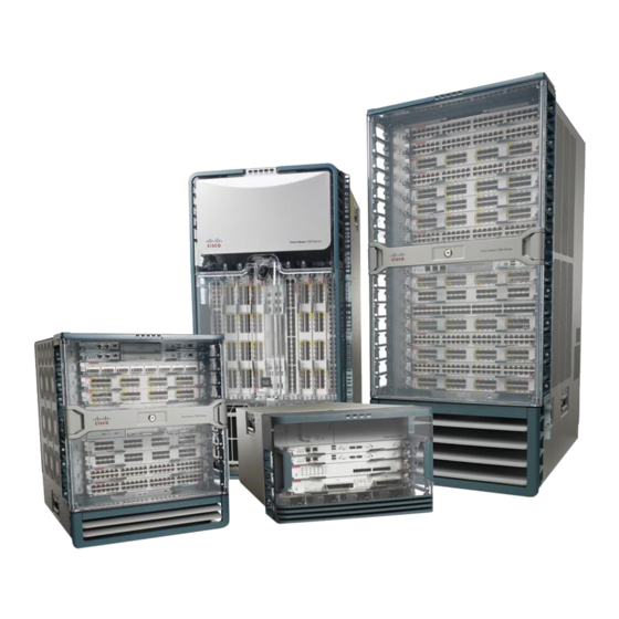
C H A P T E R Product Overview The 5-slot Cisco 7010, the newest router/bridge in the Cisco 7000 series, provides high reliability, availability, serviceability, and performance. Cisco 7000 series routers support multiprotocol, multimedia routing and bridging with a wide variety of protocols and any combination of Ethernet, Fast Ethernet, Token Ring, FDDI, serial, multichannel channel attachment, and HSSI media. -
Page 16: Physical Description
The Cisco 7010 is the entry-level model in the Cisco 7000 series product line, which currently includes the 7-slot Cisco 7000 and the 5-slot Cisco 7010. Both models use the same RP, SP (or SSP), and interface processors; all processor modules are interchangeable between the two models. The Cisco 7000 provides five interface slots and offers a second modular power supply for redundant power. - Page 17 Cisco 7000 Cisco 7010 The front, or noninterface processor end, of the Cisco 7010 is a removable cover panel that is secured with two captive slotted fasteners. (See Figure 1-2.) Removing the cover panel provides access to the three internal components: the arbiter, power supply, and fan tray.
- Page 18 Figure 1-3 shows the interface processor end of a Cisco 7010 with an AC-input power supply. Figure 1-3 Cisco 7010 —Interface Processor End...
-
Page 19: Chassis Specifications
Physical Description Chassis Specifications Table 1-2 lists the Cisco 7010 physical specifications and power requirements. Table 1-2 Cisco 7010 System Specifications Description Specification High-speed backplane 533-Mbps CxBus, 3 interface processor slots plus RP, SP, and SSP slots Dimensions (H x W x D) 10.5 x 17.5 x 17.0"... -
Page 20: Internal Components
The power supply and fan tray are available as spares. The arbiter is categorized as a field-replaceable unit (FRU), which means that it can only be replaced by a Cisco-certified technician. Note that the backplane is not a spare or an FRU. -
Page 21: Power Supply
Power Supply The Cisco 7010 comes equipped with one 550W, AC-input power supply (shown in Figure 1-4) or one 600W, DC-input power supply. The AC-input power supply operates on AC-input power and supplies DC power to the internal components. The DC-input power supply operates on DC input power and supplies DC power to the internal components. - Page 22 Figure 1-6 Internal Airflow, Top-Down View Top view of router Chassis fans Power supply fans Interface processor end Chassis airflow Power supply airflow Power supply airflow Chassis airflow Service (noninterface processor) end Fan tray 1-8 Cisco 7010 Hardware Installation and Maintenance...
-
Page 23: Fan Tray
Physical Description Fan Tray An array of six individual fans draw cooling air through the chassis interior to maintain an acceptable operating temperature for the internal components. The fan tray comprises the six fans and a printed circuit board (with the control circuits) mounted on a metal plate. (See Figure 1-4.) The fan tray slides into the right side of the chassis from the noninterface processor end of the router. - Page 24 Figure 1-8 Backplane Slot Keys Key guides on Interface processors, SP (or SSP), and RP (or SSP) Left Right Left Right key guide key guide Rear of processor module 1-10 Cisco 7010 Hardware Installation and Maintenance...
-
Page 25: Route Processor (Rp)
Physical Description Route Processor (RP) The RP, shown in Figure 1-9, is the main system processor in the router. The RP contains the system central processing unit (CPU), the system software, and most of the system memory components, and it maintains and executes the management functions that control the system. The RP contains the following components: •... - Page 26 System Software or Boot ROMs Eight EPROM components contain the default and bootstrap system software. The downloadable system software and microcode feature, which the Cisco 7000 series supports for most upgrades, allows you to remotely download, store, and boot from a new image.
- Page 27 — System Bootstrap Version 4.7(2.1) (or a later 4.7 version) — RP board revision B0 or later • If your system contains Cisco Internetwork Operating System (Cisco IOS) Release 10.0, the minimum requirements are as follows: — Release 10.0(1) (or a later 10.0 image) in ROM —...
- Page 28 Because the RP always resides in the same (RP) slot, specify slot 4 for a Cisco 7010 chassis. The third line of the display shows the current hardware (HW) and board revisions. (Do not confuse the HW revision with the board revision;...
-
Page 29: Jumpers
Physical Description EEPROM An electrically erasable programmable read-only memory (EEPROM) component on the RP (and on the SP and each interface processor) stores board-specific information such as the board serial number, part number, controller type, hardware revision, and other details unique to each board. In addition to this standard information, the RP EEPROM also contains an address allocator, which is a bank of 40 hardware or media access control (MAC)-level addresses, one for each possible port in the system. -
Page 30: 7000 Series Route Switch Processor (Rsp7000)
7000 CI slot (slot 4 in the Cisco 7010). The Cisco IOS images reside in Flash memory, which is located either on the RSP7000, in the form of a single in-line memory module (SIMM), or on up to two Personal Computer Memory Card International Association (PCMCIA) cards (called Flash memory cards) that insert in the two PCMCIA slots (slot 0 and slot 1) on the front of the RSP7000. -
Page 31: Memory Components
Contains the Cisco IOS images on the RSP7000 (standard) Flash Card 8, 16, and 20 MB Up to 2 Contains the Cisco IOS images on up to two PCMCIA cards Slot 0, slot 1 Boot ROM 256 KB EPROM for the ROM monitor program 1. - Page 32 The imbedded or PCMCIA card-based Flash memory allows you to remotely load and store multiple Cisco IOS and microcode images. You can download a new image over the network or from a local server and then add the new image to Flash or replace the existing files. You can then boot routers either manually or automatically from any of the stored images.
-
Page 33: System Software
Physical Description System Software The Cisco 7000 series routers support downloadable system software and microcode for most Cisco IOS and microcode upgrades, which enables you to remotely download, store, and boot from a new image. Flash memory contains the default system software. An erasable programmable read-only memory (EPROM) device contains the latest microcode version, in compressed form, for each interface processor. -
Page 34: Switch Processor (Sp)
The RSP7000CI requires that your Cisco 7000 is running Cisco IOS Release 10.3(9) or later. Note You must also have the RSP7000 installed in the 7000 RSP slot (slot 3 in the Cisco 7010). The functions of the RSP7000CI are as follows: •... -
Page 35: Silicon Switch Processor (Ssp)
(Cisco IOS) Release 10.0, or later. • The SSP with 2 MB of packet memory requires Cisco IOS Release 10.0 or later. Cisco IOS Releases 10.2(x) and 10.3(x) will provide the best use of the 2-MB SSP. (Detailed procedures for upgrading your Cisco 7000 series router software are provided separately with the software upgrade.) -
Page 36: Atm Interface Processor (Aip)
The early serial interface processor (SX-SIP or PRE-FSIP) cannot be used in the Caution Cisco 7010 (the SX-SIP requires SxBus connectors that are not present in the Cisco 7010). In October 1993, the FSIP replaced the SIP in the product line, and most SIPs in the field have now been replaced with FSIPs. - Page 37 Traffic from multiple ATM network interfaces could theoretically exceed the bandwidth of Note the CxBus. This would cause packets to be dropped. As a practical limit, Cisco 7000 series routers can contain up to two AIP modules per chassis. The AIP supports the following features: •...
-
Page 38: Channel Interface Processor (Cip)
The ECA and PCA adapters can be upgraded or replaced in the field by a Cisco-certified maintenance provider only. While up to three CIPs can be installed in the Cisco 7010, we recommend that you leave one slot available for a WAN interface. The default CIP microcode boot image resides on an ROM in socket U37. -
Page 39: Ethernet Interface Processor (Eip)
For complete descriptions of the LED states, refer to the appendix “Reading LED Indicators.” The EIP is available with two, four, or six ports. The Cisco 7010 supports up to three EIPs for a maximum of 18 Ethernet ports. Each port requires an Ethernet transceiver or a media attachment unit (MAU) and attachment unit interface (AUI) cable to connect to the external network. -
Page 40: Fiber Distributed Data Interface Processor (Fip)
(SASs), dual-attach stations (DASs), dual homing, and optical bypass. The FIP complies with ANSI X3.1 and ISO 9314 FDDI standards. The default FIP microcode resides on a ROM in socket U23. Figure 1-17 FDDI Interface Processor (FIP), Multimode/Multimode and Single-Mode/Multimode 1-26 Cisco 7010 Hardware Installation and Maintenance... - Page 41 Each FIP provides the interface for connection to a Class A DAS (with primary and secondary rings), or to a Class B SAS (with only a primary ring). The Cisco 7010 supports up to three FIPs for a maximum of 3 FDDI network connections. The multimode MIC or single-mode FC ports on the FIP provide a direct connection to the external FDDI network.
-
Page 42: Fast Serial Interface Processor (Fsip)
The default FSIP microcode resides on a PLCC-type ROM in socket U81. The Cisco 7010 supports up to three FSIPs for a maximum of 24 high-speed serial interfaces. There are no restrictions on slot locations or sequence; you can install FSIPs in any available interface processor slots. - Page 43 Physical Description In order to provide a high density of ports, the FSIP uses special port adapters and adapter cables. A port adapter is a daughter card that provides the physical interface for two FSIP ports. Both ports use the same high-density, 60-pin universal receptacle that supports all interface types. The adapter cable connected to the port determines the interface type and mode.
- Page 44 E1-G.703/G.704 Port Adapter The FSIP E1-G.703/G.704 interface connects Cisco 7000 series routers with 2.048-Mbps leased line services. The interface eliminates the need for a separate, external data termination unit to convert a standard serial interface (such as V.35) to a G.703/G.704/G.732 interface.
- Page 45 Physical Description The FSIP can be configured to support up to eight E1-G.703/G.704 ports (four ports per module, two modules per FSIP). FSIP bandwidth can be allocated by the user, and the maximum aggregate bandwidth per four-port module is 16 Mbps, full duplex. We recommend that you leave one port on each module shut down to avoid exceeding this 16-Mbps maximum per module.
-
Page 46: Hssi Interface Processor (Hip)
C (Connected)—When on, indicates normal operation; the HIP is properly connected to the external DSU, and TA (DTE available) and CA (DCE available) are active. This LED is off when the HIP is in loopback mode and when it is not connected to the DSU. 1-32 Cisco 7010 Hardware Installation and Maintenance... -
Page 47: Multichannel Interface Processor (Mip)
Refer to the appropriate software configuration and command reference publications for specific configuration information. Note For T1 and E1, the Cisco 7010 supports a maximum of three MIP modules for a total of 6 MIP ports and up to 180 serial interfaces. Product Overview 1-33... -
Page 48: Token Ring Interface Processor (Trip)
For complete descriptions of the LED states, refer to the appendix “Reading LED Indicators.” The TRIP is available with two or four ports. The Cisco 7010 supports up to 3 TRIPs for a maximum of 12 Token Ring ports. Each port requires a media access unit (MAU) to connect the DB-9 TRIP connectors to the external Token Ring networks. -
Page 49: Port Densities
Other devices in the network use these addresses to locate specific ports in the network and to create and update routing tables and data structures. The Cisco 7000 series uses a unique method to assign and control the MAC-layer addresses of its interfaces. - Page 50 Serial0/0 is up, line protocol is up Hardware is cxBus Serial Internet address is 131.108.123.4, subnet mask is 255.255.255.0 (display text omitted) Ethernet1/2 is up, line protocol is up Hardware is cxBus Ethernet, address is 0000.0c02.d0f1 (bia 0000.0c02.d0f1) 1-36 Cisco 7010 Hardware Installation and Maintenance...
-
Page 51: Mac Address Allocator
However, the OIR feature makes it necessary to use a different method of handling the MAC addresses in Cisco 7000 series routers. OIR allows you to remove an interface processor and replace it with another identically-configured one. If the new interfaces match the current configuration (that of the interfaces you removed), the system immediately brings them on line. -
Page 52: Online Insertion And Removal (Oir)
When you insert a new interface processor, the system runs a diagnostic test on the new interfaces and compares them to the existing configuration. 1-38 Cisco 7010 Hardware Installation and Maintenance... -
Page 53: Microcode
Microcode The Cisco 7000 series routers support downloadable microcode for most upgrades, which enables you to load new microcode images into Flash memory instead of replacing the microcode ROMs on the boards.The latest microcode version for each interface processor type is bundled with the system software image. -
Page 54: Environmental Monitoring And Reporting Functions
(indicated as either “600W DC” or “550W AC”). Record and save this information in a secure place. 1-40 Cisco 7010 Hardware Installation and Maintenance... -
Page 55: Environmental Monitoring
Functional Overview If you are currently using software other than Maintenance Release 9.17(10) or later, then the Note show environment all command will indicate the AC-input power supply as “850W.” A DC-input power supply will still be indicated as “600W.” Environmental Monitoring The environmental monitoring functions use the following levels of status conditions to monitor the system. -
Page 56: Environmental Reports
(See Figure 1-6.) Ensure adequate clearance around the sides of the chassis so that cooling air can flow through the chassis interior unimpeded. Obstructing or blocking the chassis sides will restrict the airflow and can cause the internal chassis temperature to exceed acceptable limits. 1-42 Cisco 7010 Hardware Installation and Maintenance... - Page 57 Functional Overview The show environment command display reports the current environmental status of the system. The report displays the date and time of the query, the refresh times, the overall system status, and any parameters that are out of the normal values. No parameters are displayed if the system status is normal.
- Page 58 CRITICAL NORMAL CRITICAL -------|--------------------|------------------------|-------------------- +12(V) 10.20 12.05(V) 13.80 +5(V) 4.74 4.96(V) 5.76 -12(V) -10.20 -12.05(V) -13.80 +24(V) 20.00 23.80(V) 28.00 Temperature Parameters: SENSE WARNING NORMAL WARNING CRITICAL SHUTDOWN ------|-------------|------------|-------------|--------------|------------ Inlet 32(C) Air-flow 40(C) 1-44 Cisco 7010 Hardware Installation and Maintenance...
-
Page 59: Fan Shutdown
Functional Overview The following example shows only the Temperature Parameters section of the table. In this example, the measured value at the inlet sensor is 41°C, which falls within the warning range (39°C through 46°C) and therefore is displayed in the Warning column. Temperature Parameters: SENSE WARNING... - Page 60 Queued messages: %ENVM-1-SHUTDOWN: Environmental Monitor initiated shutdown For complete command descriptions and instructions, refer to the related software configuration and command reference documentation. 1-46 Cisco 7010 Hardware Installation and Maintenance...
-
Page 61: Preparing For Installation
C H A P T E R Preparing for Installation This chapter describes the equipment and site requirements for router installation. It includes the power and cabling requirements that must be in place at the installation site, descriptions of additional equipment you will need to complete the installation, and the environmental conditions your site must meet to maintain normal operation. -
Page 62: Safety Recommendations
Warning Lifting Safely A fully configured Cisco 7010 weighs approximately 70 pounds. The chassis is not intended to be moved frequently. Before you install the router, ensure that your site is properly prepared, so you can avoid having to move the chassis later to accommodate power sources and network connections. -
Page 63: Preventing Electrostatic Discharge Damage
Safety Recommendations • Do not work alone when potentially hazardous conditions exist. • Never assume that power has been disconnected from a circuit; always check. • Do not perform any action that creates a potential hazard to people or makes the equipment unsafe. -
Page 64: Site Requirements
The 600W, DC-input power supply allows the Cisco 7010 to operate between –40 and –52 VDC (–48 VDC nominal). In the European Community, the power supply operates between –56 VDC and –72 VDC (–60 VDC nominal). -
Page 65: Interference Considerations
Site Requirements Interference Considerations When wires are run for any significant distance in an electromagnetic field, interference can occur between the field and the signals on the wires. This fact has two implications for the construction of plant wiring: • Bad wiring practice can result in radio interference emanating from the plant wiring. - Page 66 – 1. EIA/TIA-568 or EIA/TIA-568 TSB-36 compliant. 2. Cisco Systems does not supply Category 5 UTP RJ-45 or 150-ohm STP MII cables. Both are commercially available. 3. AWG = American Wire Gauge. This gauge is specified by the EIA/TIA-568 standard.
- Page 67 Site Requirements Table 2-3 IEEE 802.3u Physical Characteristics 100BaseT Data rate (Mbps) Signalling method Baseband Maximum segment length (meters) Media Topology Star 1. UTP = unshielded twisted pair. MultiChannel Connections Following are the MIP T1 specifications: • Transmission bit rate: 1.544 kilobits per second (kbps) ± 50 parts per million (ppm) •...
- Page 68 As with all signaling systems, serial signals can travel a limited distance at any given bit rate; generally, the slower the baud rate, the greater the distance. Table 2-6 shows the standard relationship between baud rate and distance for EIA/TIA-232 signals. 2-8 Cisco 7010 Hardware Installation and Maintenance...
- Page 69 Site Requirements Table 2-6 IEEE Standard EIA/TIA-232C Transmission Speed versus Distance Distance Rate (bps) Distance (Feet) (Meters) 2400 4800 9600 19200 38400 56000 Balanced drivers allow EIA/TIA-449 signals to travel greater distances than EIA/TIA-232. Table 2-7 shows the standard relationship between bit rate and distance for EIA/TIA-449 signals. Table 2-7 IEEE Standard EIA/TIA-449 Transmission Speed versus Distance Rate (bps)
- Page 70 (smear). Higher order mode loss (HOL) results from light from the LED entering the fiber and being radiated into the fiber cladding. A worst case estimate of power margin (PM) for 2-10 Cisco 7010 Hardware Installation and Maintenance...
- Page 71 Site Requirements multimode transmissions assumes minimum transmitter power (PT), maximum link loss (LL), and minimum receiver sensitivity (PR). The worst case analysis provides a margin of error, although not all of the parts of an actual system will operate at the worst case levels. The power budget (PB) is the maximum possible amount of power transmitted.
- Page 72 –8 dB, while the receiver could be overloaded at –14 dB, but no damage to the receiver will result. To prevent overloading the receiver connecting short fiber links, insert a 5 to 10 dB attenuator on the link between any single-mode SONET transmitter and the receiver. 2-12 Cisco 7010 Hardware Installation and Maintenance...
-
Page 73: Hssi Connections
Site Requirements SONET Single-Mode Power Budget Example The following example of a single-mode power budget is of a two buildings, 11 kilometers apart, connected through a patch panel in an intervening building with a total of 12 connectors. Length of single-mode link = 11 km 12 connectors Estimate the power budget as follows: PB = 11.5 dB –... - Page 74 Some Telco-type racks are also secured to ceiling brackets, if warranted by the weight of the equipment in the rack. In addition to the preceding guidelines, review the precautions for avoiding overtemperature conditions in the section “Equipment-Rack Ventilation” in this chapter. 2-14 Cisco 7010 Hardware Installation and Maintenance...
-
Page 75: Site Environment
Site Requirements Figure 2-1 Chassis Footprint and Outer Dimensions Chassis foot C 14.25 in. (36.20 cm) 2 in. Power supply width (5.08 cm) 14.60 in. to ears (37.08 cm) Noninterface processor end 1.25 in. (3.18 cm) Interface processor end Interface processor width 14.55 in. -
Page 76: Preventive Site Configuration: Maintaining Normal Operation
In addition, chassis panels made inaccessible by poor equipment placement can make system maintenance difficult. Following are precautions that can help avoid problems during installation and ongoing operation. 2-16 Cisco 7010 Hardware Installation and Maintenance... -
Page 77: General Precautions
Site Requirements General Precautions Follow these general precautions when planning your equipment locations and connections: • Use the show environment command regularly to check the internal system status. The environmental monitor continuously checks the interior chassis environment; it provides warnings for high temperature and maximum and minimum voltages, and creates reports on any occurrences. -
Page 78: Power
DIN-to-mini-DIN control cable for connecting the switch is included with the multimode/multimode FIP (CAB-FMDD). • To use a low-speed synchronous serial interface, you need a synchronous modem or a (CSU/DSU to connect to the network. Most modems require an EIA/TIA-232 DTE connection. 2-18 Cisco 7010 Hardware Installation and Maintenance... -
Page 79: Atm Connection Equipment
To connect two routers directly back to back between HSSI ports, you need a null modem cable (CAB-HNUL). The two routers must be in the same location and can be two Cisco 7000 series routers, two AGS+ routers, or one of each; both routers must have a HSSI port available. - Page 80 Figure 2-2 Multimode Network Interface Connector (MIC Type) For SONET/SDH multimode connections, use one multimode duplex SC connector (see Figure 2-3) or two single SC connectors. (See Figure 2-4.) Figure 2-3 Duplex SC Connector 2-20 Cisco 7010 Hardware Installation and Maintenance...
- Page 81 Preparing Network Connections Figure 2-4 Simplex SC Connector For SONET/SDH single-mode connections, use the single-mode (ST2) connector (bayonet-style twist-lock). (See Figure 2-5.) Figure 2-5 ST2 Connector Invisible laser radiation can be emitted from the aperture ports of the single-mode ATM Warning products when no fiber-optic cable is connected.
- Page 82 The SONET multimode SC-duplex connector is shipped with a dust plug. (See Figure 2-9.) Remove the plug by pulling on the plug as you squeeze the sides. Figure 2-9 SONET ATM Multimode Fiber-Optic Transceiver and Dust Plug 2-22 Cisco 7010 Hardware Installation and Maintenance...
-
Page 83: Channel Attachment Connection Equipment
The ESCON Channel Adapter (ECA) and bus and tag Parallel Channel Adapter (PCA) for the CIP are available as FRUs; however, they are field replacable by Cisco-certified field service personnel only. For more information on the ECA, PCA, and CIP, refer to the configuration note Channel Interface Processor (CIP) Installation and Configuration (Document Number 78-1342-xx, where xx is the latest revision of the document). - Page 84 Data rate (Mbps) Signaling method Baseband Baseband Baseband Baseband Max. segment 500m 500m 185m 100m (UTP) length Media 50-ohm coax 50-ohm coax 50-ohm coax Unshielded twisted pair (thick) (thick) (thin) (UTP) Topology Star 2-24 Cisco 7010 Hardware Installation and Maintenance...
- Page 85 Preparing Network Connections Ethernet is most similar to IEEE 802.3 10Base5. Both of these protocols specify a bus topology network with a connecting cable between the end stations and the actual network medium. Both protocols require a device that acts as an interface between the end stations (the EIP) and the actual network medium (cable).
- Page 86 The most common are those that use a slide-type lock, which is the type used on the EIP ports. The connector on the left in Figure 2-14 shows a slide-type lock. When the cable is connected to the 2-26 Cisco 7010 Hardware Installation and Maintenance...
-
Page 87: Fast Ethernet Connection Equipment
Preparing Network Connections 15-pin port, a metal bracket snaps up over two posts on the cable connector to secure it in the port and provide strain relief. Instead of the posts and sliding bracket, the jackscrew-type lock (shown on the right in Figure 2-14) uses two thumbscrews or jackscrews, which are usually attached to the cable connector. -
Page 88: Token Ring Connection Equipment
Caution connected, either 4 or 16 Mbps. If the port is set for a different speed, it will cause the ring to beacon, which effectively brings the ring down and makes it inoperable. 2-28 Cisco 7010 Hardware Installation and Maintenance... -
Page 89: Token Ring Cables And Connectors
Preparing Network Connections Token Ring Cables and Connectors The Token Ring ports on the TRIP are DB-9 (PC type) receptacles that require Type 1 or Type 3 lobe cables. Type 1 lobe cables use shielded twisted pair cable and terminate at the network end with a large MAU plug. - Page 90 The busy token, with the information frame, circulates the ring until it reaches the intended destination station, which copies the information for further processing and passes the busy token and information frame back out to the ring. 2-30 Cisco 7010 Hardware Installation and Maintenance...
-
Page 91: Token Ring Fault Management
Preparing Network Connections The information frame continues to circle the ring until it reaches the original sending station, which checks the returned frame to ensure that the destination station received the information. When the original sending station determines that the receiving station accepted the information, it purges the token and information frame, and transmits a new free token out to the ring. -
Page 92: Fddi Connection Equipment
LEDs as a light source, and single-mode transmitters use a laser diode, which is capable of sustaining faster data rates. Both types use a photodiode detector at the receiver to translate the light signal into electrical signals. 2-32 Cisco 7010 Hardware Installation and Maintenance... -
Page 93: Fddi Transceivers And Cable Connectors
Preparing Network Connections FDDI Transceivers and Cable Connectors The FIP single-mode interface uses simplex FC-type connectors for the Transmit and Receive ports. (See Figure 2-20.) The connector accepts standard 8.7 to 10/125-micron single-mode fiber-optic cable. The single-mode interface supports connections at distances up to 6 miles (10 kilometers). Figure 2-20 Single-Mode FDDI Network Interface Connectors, FC Type The multimode transceiver supports distances of up to 1.2 miles (1.9 kilometers). -
Page 94: Fddi Fault Management
Station 1 and from PHY B on Station 1 to PHY A on Station 4. Using Station 1 as a reference, Station 2 is the upstream neighbor of Station 1, and Station 4 is the downstream neighbor of Station 1. 2-34 Cisco 7010 Hardware Installation and Maintenance... - Page 95 Preparing Network Connections Figure 2-23 DAS Station Failure and Ring Recovery Example Station 1 Station 4 Station 2 Ring wrap Ring wrap Failed station Station 3 A second failure could cause the ring to wrap in both directions from the point of failure, which would segment the ring into two separate rings that could not communicate with each other.
-
Page 96: Multichannel (Mip) Connection Equipment
CSU. Figure 2-25 shows the MIP interface cable, connectors and pin-outs. Figure 2-25 MIP Interface Cable Connector in 1 Pin 3 in 9 Pin 11 in 11 Pin 9 in 3 Pin 1 T1 or null-modem connector (typical) 2-36 Cisco 7010 Hardware Installation and Maintenance... -
Page 97: Serial Connection Equipment
Preparing Network Connections For E1, four serial cables are available from Cisco Systems for use with the MIP. All three have DB-15 connectors on the MIP end and either BNC, DB-15, Twinax, or RJ-45 connectors on the network end. Figure 2-26, Figure 2-27, Figure 2-28, and Figure 2-29 show the E1 interface cables (respectively). -
Page 98: Universal Serial Cables
EIA/TIA-449: DTE mode with 37-pin D-shell plug; DCE mode with 37-pin D-shell receptacle • V.35: DTE mode or DCE mode with 34-pin Winchester-type V.35 plug; DTE mode or DCE mode with 34-pin Winchester-type V.35 receptacle 2-38 Cisco 7010 Hardware Installation and Maintenance... -
Page 99: E1-G.703/G.704 Cables
Preparing Network Connections • X.21: DTE mode with DB-15 plug; DCE mode with DB-15 receptacle • EIA-530: DTE mode with DB-25 plug E1-G.703/G.704 Cables Figure 2-31, Figure 2-32, and Figure 2-33 show the unbalanced and balanced cables used for connection between the E1-G.703/G.704 port adapter and your network. The port-adapter end of each cable has a DB-15 connector. -
Page 100: Cyclic Redundancy Checks (Crcs)
For brief descriptions of the clockrate and invert-transmit-clock commands, refer to the section “Configuring Timing (Clock) Signals” in the chapter “Maintenance.” For complete command descriptions and instructions, refer to the related software documentation. 2-40 Cisco 7010 Hardware Installation and Maintenance... -
Page 101: Eia/Tia-232 Connections
Preparing Network Connections All serial signals are subject to distance limits, beyond which a signal degrades significantly or is completely lost. For specific cabling distance limitations, refer to the section “Distance Limitations” in this chapter. The distance and rate limits in these descriptions are the IEEE-recommended maximum speeds and distances for signaling;... -
Page 102: V.35 Connections
(network) end of the adapter cable is a standard DB-15 connector. Figure 2-37 shows the connectors at the network end of the X.21 adapter cable. X.21 cables are available as either DTE (DB-15 plug) or DCE (DB-15 receptacle). 2-42 Cisco 7010 Hardware Installation and Maintenance... -
Page 103: M3 Metric Thumbscrew Replacements
Preparing Network Connections Figure 2-37 X.21 Adapter Cable Connectors, Network End EIA-530 Connections EIA-530, which supports balanced transmission, provides the increased functionality, speed, and distance of EIA/TIA-449 on the smaller, DB-25 connector used for EIA/TIA-232. The EIA-530 standard was created to support the more sophisticated circuitry of EIA/TIA-449 on the masses of existing EIA/TIA-232 (DB-25) hardware instead of the larger, 37-pin connectors used for EIA/TIA-449. -
Page 104: Console And Auxiliary Port Connection Equipment
CSU/DSU, or other DCE equipment. You also must supply your own interface cable between the auxiliary port and the equipment you are connecting. For console and auxiliary port pinouts, refer to the appendix “Cabling Specifications.” 2-44 Cisco 7010 Hardware Installation and Maintenance... -
Page 105: Tools For Installation
Tools for Installation Tools for Installation The chassis is fully assembled at the factory; no assembly is required. Following are the tools and equipment you will need to install the chassis and the rack-mount kit: • Number 1 Phillips and 3/16-inch flat-blade screwdrivers to tighten the captive installation screws on the interface processors (most interface processor carriers use slotted screws, but some use Phillips-head screws). -
Page 106: Installation Checklist
Router hardware and software documentation, if ordered (see the following Note) Note Cisco no longer automatically ships a hard copy of the entire router documentation set with each system. This documentation is available on UniverCD, which can be obtained at no charge when a router order is placed. -
Page 107: System Components
Initial Configuration Information Check the processor slots and verify that the top slot contains an RP, and the slot directly Step 3 below the RP contains an SP (or SSP). (See Figure 1-3.) Each of the lower three processor slots (the interface processor slots) each contain an Step 4 interface processor or a blank interface processor filler. - Page 108 [or SSP] and all interface processors is on) Console screen displays correct hardware configuration (displayed after system banner) System ready for global and interface-specific configuration 1. Refer to the related software documentation for first-time software configuration requirements. 2-48 Cisco 7010 Hardware Installation and Maintenance...
- Page 109 Flash memory card MAU, CSU/DSU for network connections Documentation Cisco 7000 User Guide and UniverCD (ship with chassis), and any printed documentation as ordered System components: Processor slots 5 and 6 should contain an SP (or SSP) and RP, or an RSP7000 (slot 5) and an...
- Page 110 AC-input power supply Table 2-17 Port Configuration Worksheet Slot 0—Refer to Figure 2-40 Slot 1—Refer to Figure 2-40 Slot 2—Refer to Figure 2-40 Port 0 Port 1 Port 2 Port 3 Port 4 2-50 Cisco 7010 Hardware Installation and Maintenance...
- Page 111 Initial Configuration Information Slot 0—Refer to Figure 2-40 Slot 1—Refer to Figure 2-40 Slot 2—Refer to Figure 2-40 Port 5 Port 6 Port 7 Router Name ____________ Location ___________________ Serial Number _____________ Table 2-18 Site Log for ___________________________________________________________ Date Description of Action Performed or Symptom Observed Initials Preparing for Installation 2-51...
- Page 112 Initial Configuration Information Page ________ 2-52 Cisco 7010 Hardware Installation and Maintenance...
-
Page 113: Installing The Router
C H A P T E R Installing the Router This chapter provides the following procedures for installing the router, making all external cable connections, turning on the system power, and verifying that the system initializes properly: • Installing the chassis in an equipment rack (optional) or on a table top •... -
Page 114: Tools And Equipment
When installing the router in an enclosed rack, removing the door temporarily may provide additional clearance. We recommend that you have someone to assist you by supporting the chassis while you mount it in the rack by securing the chassis ears to the rack-mounting strips. 3-2 Cisco 7010 Hardware Installation and Maintenance... -
Page 115: Installing The Ears On The Chassis
Rack-Mounting the Chassis Installing the Ears on the Chassis The chassis should be unpacked, and you should have already verified the router configuration. Each chassis ear has two studs that fit into holes in the chassis. The chassis has two pairs of holes on each side: one pair near the interface processor end and one pair near the noninterface processor end. -
Page 116: Installing The Chassis In The Rack
If removal is necessary, use a 3/16-inch flat-blade screwdriver to remove the feet, then put the feet in a safe place in case you need them later. 3-4 Cisco 7010 Hardware Installation and Maintenance... - Page 117 Rack-Mounting the Chassis Unless you have a way of supporting the chassis in the rack while you install the fasteners, get another person to assist you so that one person can support the chassis while the other installs the fasteners. Ensure that heavier equipment is installed near the bottom of the rack to maintain a low Warning center of gravity.
-
Page 118: General Installation
A raised platform or sturdy table provides a cleaner environment than the floor. • When deciding where to install any equipment, consider future maintenance requirements. Allow adequate clearance for maintenance (installing/replacing interface processors, or making/adding network connection cables or equipment). 3-6 Cisco 7010 Hardware Installation and Maintenance... -
Page 119: Installing The Cable Management Brackets
Installing the Cable Management Brackets If you do not mount the router in a rack, follow these steps to install the router on a bench or tabletop: Make sure that the area where you install the router is free of debris and dust. Also make Step 1 sure your path between the router and its planned location is unobstructed. -
Page 120: Tools And Equipment
Loosen the captive screws on the terminal block cover so it is free of the terminal block. Step 2 (See Figure 3-6a.) Attach the 10-AWG ground wire to the ground terminal. (See Figure 3-6d.) Step 3 3-8 Cisco 7010 Hardware Installation and Maintenance... - Page 121 Incorrectly wiring the terminal block could create a shock hazard and could damage the power supply, power source, and the Cisco 7010 chassis components. Make certain there are no loose strands that could cause a short circuit of the power supply and power source.
-
Page 122: Connecting Interface Cables
Each port has a unique address composed of the interface processor slot number and the port number on the interface processor. For a description of interface addresses, refer to the section “Port Addresses” in the chapter “Product Overview.” • Avoid crossing high-power cables with interface cables. 3-10 Cisco 7010 Hardware Installation and Maintenance... -
Page 123: Tools And Equipment
Connecting Interface Cables Crossing high-power cables with interface cables can cause interference in some interface types. It will not always be possible to avoid this, but try to prevent it whenever possible. • Install and use the cable management brackets. •... -
Page 124: Atm Connections
E3 PLIM and your ATM switch, respectively. Step 2 Hold the EMI filter clip as shown in Figure 3-8b and attach it to the receive cable as shown in Figure 3-8c. 3-12 Cisco 7010 Hardware Installation and Maintenance... - Page 125 Connecting Interface Cables To ensure that the clip is not pulled off when adjacent interface processors are removed, Step 3 position the clip parallel to the orientation of the AIP. (See Figure 3-8d.) Figure 3-8 Installing the CAB-ATM-DS3/E3 Cable and EMI Filter Clip Assembly—Horizontal Orientation Shown White insulator White insulator...
-
Page 126: Ethernet Connections
FEIP, you can use the RJ-45 connection on one and the MII connection on the other. RJ-45 and MII cables are not available from Cisco Systems. If you have RJ-45 connections, attach the Category 5 UTP cable directly to the RJ-45 port on the FEIP. -
Page 127: Channel Attachment Connections
Connecting Interface Cables MII cable RJ-45 cable To transceiver, To repeater repeater, or DTE or DTE Caution To prevent problems on your FEIP and network, do not simultaneously connect RJ-45 and MII cables to one 100BaseT port adapter. On a single 100BaseT port adapter, only one network connection can be used at one time. -
Page 128: Fddi Connections
Each station in a ring refers to its neighbor stations as upstream or downstream neighbors. The stream is based on the signal flow on the primary ring. A station receives the primary signal from its upstream neighbor and transmits the primary signal to its downstream neighbor. 3-16 Cisco 7010 Hardware Installation and Maintenance... -
Page 129: Single Attach Connections
Connecting Interface Cables This section also provides instructions for connecting an optical bypass switch to a dual attachment multimode network connection. Because the method of connecting optical bypass switches varies between different manufacturer’s models, refer to the documentation for your particular bypass switch for correct connection instructions. -
Page 130: Dual Attach Connections
— Connect the cable coming in from the secondary ring to the FIP PHY B receive port. — Connect the cable going out to the secondary ring to the FIP PHY A transmit port. 3-18 Cisco 7010 Hardware Installation and Maintenance... - Page 131 Connecting Interface Cables Figure 3-15 Dual Attach Station (DAS), Single-Mode Fiber Network Connections Single-mode, dual attachment. Use four single-mode cables for a dual attachment connection. PHY B PHY A FC connectors (4) To primary ring From primary ring From secondary ring To secondary ring •...
-
Page 132: Installing An Optical Bypass Switch
FIP (CX-FIP-MM) and the single-mode/single-mode FIP (CX-FIP-SS). Figure 3-18 CX-FIP-MM Connection with Optical Bypass Optical bypass Optical bypass switch control cable PHY A ring PHY B Bypass operation Figure 3-19 CX-FIP-SS Connection with Optical Bypass 3-20 Cisco 7010 Hardware Installation and Maintenance... - Page 133 Connecting Interface Cables PHY A PHY B TX RX TX RX Optical bypass Optical bypass switch control cable To primary ring From secondary ring To secondary ring From primary ring Bypass operation The optical bypass control port on the FIP is a six-pin mini-DIN receptacle. Some optical bypass switches use DIN connectors, and some use a mini-DIN.
-
Page 134: Serial Connections
For an example configuration using this command, refer to the section “Configuring Timing (Clock) Signals” in the chapter “Maintenance.” For complete command descriptions and instructions, refer to the related software configuration and command reference documentation. 3-22 Cisco 7010 Hardware Installation and Maintenance... -
Page 135: Connecting To Metric-Based Devices
SX-SIP, or PRE-FSIP, does not operate in the Cisco 7010. (The SIP requires SxBus connectors that are not present on the Cisco 7010 backplane.) The SIP and FSIP each use unique interface cables that are not interchangeable. (The SIP uses DB-15 or DB-25 plugs and receptacles; all FSIP ports are 60-pin receptacles and the cables use 60-pin plugs.) -
Page 136: Hssi Connections
HSSI ports in two separate routers. The two routers must be in the same location, and can be two Cisco 7000 series, two AGS+’s, or one of each. When you configure the ports, you must enable the internal transmit clock on in the HSSI interface in both routers with the command hssi internal-clock. -
Page 137: Multichannel Connections
HSSI Null Modem Connection MultiChannel Connections For the MIP, two standard T1 serial cables are available from Cisco Systems and other vendors for use with the MIP: null-modem and straight-through. These interface cables are used to connect your router to external CSUs. -
Page 138: Connecting Auxiliary Port Equipment
The system power cord is connected and secured with the cable retention clip. • The Flash memory card, if present, is inserted all the way into its slot on the RP (or RSP7000). 3-26 Cisco 7010 Hardware Installation and Maintenance... - Page 139 GS Software (GS7), Version 10.3(1) Copyright (c) 1986-1995 by Cisco Systems, Inc. Compiled Wed 15-Mar-95 11:06 When you start up the router for the first time, the system automatically enters the setup...
-
Page 140: Using The Flash Memory Card
To boot from the Flash memory card, a Cisco 7010 router must be using Cisco IOS Release Note 11.0 or later boot ROMs. - Page 141 Using the Flash Memory Card Figure 3-27 Installing the Metal Sleeve Connector end CAUTION! Hold the Flash memory card with the connector end of the card toward the PCMCIA slot. Step 2 The product label should face to the right, as shown in Figure 3-28a. The Flash memory card is keyed and cannot be seated the wrong way.
- Page 142 Using the Flash Memory Card Figure 3-28 Installing and Removing a Flash Memory Card CAUTION! CAUTION! CAUTION! 3-30 Cisco 7010 Hardware Installation and Maintenance...
-
Page 143: Formatting The Flash Memory Card
However, a spare Flash memory card is shipped blank and must be reformatted before use. Also, if you plan to use a Flash memory card that was formatted on an RSP-based system (Cisco 7500 series), you must first reformat the card on your system. - Page 144 Loading new.image from 1.1.1.1 (via Ethernet1/0): !!!!!!!!!!!!!!!!!!!!!!!!!!!!!! !!!!!!!!!!!!!!!!!!!!!!!!!!!!!!!!!!!!!!!!!!!!!!!!!!!!!!!!!!!!!!!!!!!!!!!!!!!!!!!! !!!!!!!!!!!!!!!!!!!!!!!!!!!!!!!!!!!!!!!!!!!!!!!!!!!!!!!!!!!!!!!!!!!!!!!!!!!!!!!! !!!!!!!!!!!!!!!!!!!!!!!!!!!!!!!!!!!!!!!!!!!!!!!!!!!!!!!!!!!!!!!!!!!!!!!!!!!!!!!! !!!!!!!!!!!!!!!!!!!!!!!!!!!!!!!!!!!!!!!!!!!!!!!!!!!!!!!!!!!!!!!!!!!!!!!!!!!!!!!! !!!!!!!!!!!!!!!!!!!!!!!!!!!!!!!!!!!!!!!!!!!!!!!!!!!!!!!!!!!!!!!!!!!!!!!!!!!!!!!! !!!!!!!!!!!!!!!!!!!!!!!!!!!!!!!!!!!!!!!!!!!!!!!!!!!!!!!!!!!!!!!!!!!!!!!!!!!!!!!! !!!!!!!!!!!!!!!!!!!!!!!!!!!!!!!!!!!!!!!!!!!!!!!!!!!!!!!!!!!!!!!!!!!!!!!!!!!!!!!! !!!!!!!!!!!!!!!!!!!!!!!!!!!!!!!!!!!!!!!!!!!!!!!!!!!!!!!!!!!!!!!!!!!!!!!!!!!!!!!! !!!!!!!!!!!!!!!!!!!!!!!!!!!!!!!!!!!!!!!!!!!!!!!!!!!!!!!!!!!!!!!!!!!!!!!!!!!!!!!! !!!!!!!!!!!!!!!!!!!!!!!!!!!!!!!!!!!!!!!!!!!!!!!!!!!!!!!!!!!!!!!!!!!!!!!!!!!!!!!! !!!!!!!!!!!!!!!!!!!!!!!!!!!!!!!!!!!!!!!!!!!!!!!!!!!!!!!!!!!!!!!!!!!!!!!!!!!!!!!! !!!!!!!!!!!!!!!!!!!!!!!!!!!!!!!!!!!!!!!!!!!!!!!!!!!!!!!!!!!!!!!!!!!!!!!!!!!!!!!! !!!!!!!!!!!!!!!!!!!!!!!!!!!!!!!!!!!!!!!!!!!!!!!!!!!!!!!!!!!!!!!!!!!!!!!!!!!!!!!! !!!!!!!!!!!!!!!!!!!!!!!!!!!!!!!!!!!!!!!!!!!!!!!!!!!!!!!!!!!!!!!!!!!!!!!!!!!!!!!! !!!!!!!!!!!!!!!!!!!!!!!!!!!!!!!!!!!!!!!!!!!!!!!!!!!!!!!!!!!!!!!!!!!!!!!!!!!!!!!! !!!!!!!!!!!!!!!!!!!!!!!!!!!!!!!!!!!!!!!!!!!!!!!!!!!!!!!!!!!!!!!!!!!!!!!!!!!!!!!! !!!!!!!!!!!!!!!!!!!!!!!!!!!!!!!!!!!!!!!!!!!!!!!!!!!!!!!!!!!!!!!!!!!!!!!!!!!!!!!! !!!!!!!!!!!!!!!!!!!!!!!!!!!!!!!!!!!!!!!!!!!!!!!!!!!!!!!!!!! [OK - 7799951/15599616 bytes] CCCCCCCCCCCCCCCCCCCCCCCCCCCCCCCCCCCCCCCCCCCCCCCCCCCCCCCCCCCCCCCCCCCCCCCCCCCCCCCC CCCCCCCCCCCCCCCCCCCCCCCCCCCCCCCCCCCCCCCCCCCCCCCCCCCCCCCCCCCCCCCCCCCCCCCCCCCCCCCC CCCCCCCCCCCCCCCCCCCCCCCCCCCCCCCCCCCCCCCCCCCCCCCCCCCCCCCCCCCCCCCCCCCCCCCCCC Router# 3-32 Cisco 7010 Hardware Installation and Maintenance...
-
Page 145: Making The Flash Memory Card Image Bootable
Using the Flash Memory Card In the previous example, the exclamation points (!!!) appear as the file is downloaded and the Note “C” characters signify calculation of the checksum, which is a verification that the file has been correctly downloaded to the Flash memory card. Making the Flash Memory Card Image Bootable Use the following series of commands to make the image (the file named new.image) bootable. -
Page 146: Copying To The Flash Memory Card
Flash memory card with the format command. Formatting a Flash memory card to recover from locked blocks will cause existing data to Caution be lost. 3-34 Cisco 7010 Hardware Installation and Maintenance... -
Page 147: Flash Memory Card Compatibility
In order to boot from the Flash memory card, the card must have been formatted on an RP board. Therefore, if you want to boot from a card formatted on an RSP board (Cisco 7500 series), you must first reformat it. - Page 148 Using the Flash Memory Card 3-36 Cisco 7010 Hardware Installation and Maintenance...
-
Page 149: Troubleshooting The Installation
C H A P T E R Troubleshooting the Installation Your router went through extensive testing and burn-in before leaving the factory. However, if you encounter problems starting up, use the information in this chapter to help isolate the cause. Problems with the initial startup will most likely be caused by the source power or an interface processor that has become dislodged from the backplane. - Page 150 LED on Check system Reseat state with Fan Tray RP LEDs and restart Reinsert IP/SP interface Verify LEDs Enabled processors Enabled LED on and restart LED goes on System Obtain startup technical successful assistance 4-2 Cisco 7010 Hardware Installation and Maintenance...
-
Page 151: Problem Solving With Subsystems
Problem Solving with Subsystems The rest of this chapter describes troubleshooting methods and defines how the router is divided into subsystems for more efficient problem solving. A description of a normal startup sequence contains pointers to sections in this chapter that contain troubleshooting procedures for specific components so that you can determine where your system is having trouble and then troubleshoot that specific component or subsystem. - Page 152 — If the DC OK LED is on but the fans are not operating, there is a problem with the fan tray or with one of the fans. (The system will shut itself down if it detects that any of the fans are not functioning properly.) Proceed to the section “Troubleshooting the Cooling Subsystem.” 4-4 Cisco 7010 Hardware Installation and Maintenance...
- Page 153 (c) (1) (ii) of the Rights in Technical Data and Computer Software clause at DFARS sec. 252.227-7013. cisco Systems, Inc. 170 West Tasman Drive San Jose, California 95134-1706 GS Software (GS7), Version 10.3(1) [fc3], RELEASE SOFTWARE Copyright (c) 1986-1995 by cisco Systems, Inc. Troubleshooting the Installation 4-5...
-
Page 154: Troubleshooting The Power Subsystem
If the DC OK LED then goes on, the power cable is faulty. (The AC power cable for the Cisco 7000 is compatible with the Cisco 7010. You supply the DC power cable.) —... -
Page 155: Troubleshooting The Processor Subsystem
Troubleshooting the Processor Subsystem — If yes, the +24 VDC line to the fan tray is good, but there might be a problem with the software or an individual fan. — If no, there is a problem with the fan tray or the +24 VDC power. Ensure that the DC OK LED is on. -
Page 156: Troubleshooting The Rp And Sp (Or Ssp)
• Are all SP (or SSP) and interface processor enabled LEDs on? — If yes, the system is operational. Proceed to the instructions for configuring the interfaces in the appropriate software configuration documentation. 4-8 Cisco 7010 Hardware Installation and Maintenance... - Page 157 Troubleshooting the Processor Subsystem • Are any SP (or SSP) and interface processor enabled LEDs on? — If none of the enabled LEDs are on, first check the RP normal LED, which will be on if the system booted successfully. The normal LED should be on if the system. —...
- Page 158 Troubleshooting the Processor Subsystem 4-10 Cisco 7010 Hardware Installation and Maintenance...
-
Page 159: Maintenance
This chapter provides maintenance procedures for the Cisco 7010 router and its components. Your Cisco 7010 is configured to your order and ready for installation and startup when it leaves the factory. In the future, as your communication requirements change, you may want to upgrade your system, add components, or change the initial configuration. -
Page 160: Installing And Configuring Processor Modules
You do not need to notify the software or shutdown the system power. When you remove or insert an interface processor, the backplane pins send signals to notify the system, which then performs as follows: 5-2 Cisco 7010 Hardware Installation and Maintenance... -
Page 161: Tools Required
Installing and Configuring Processor Modules Rapidly scans the backplane for configuration changes and does not reset any interfaces. Initializes all newly inserted interface processors, noting any removed interfaces and placing them in the administratively shutdown state. Brings all previously configured interfaces on the interface processor back to the state they were in when they were removed. -
Page 162: Ejector Levers
Following are detailed steps for removing and replacing interface processors and successfully performing OIR. Figure 5-1 shows the functional details of the ejector levers, which you must use properly when inserting or removing interface processors. 5-4 Cisco 7010 Hardware Installation and Maintenance... - Page 163 Installing and Configuring Processor Modules Figure 5-1 Ejector Levers and Captive Installation Screws Interface processor card slot Ejector lever Interface processor card carrier guide (black) Captive installation screw Maintenance 5-5...
-
Page 164: Removing And Replacing The Rp, Sp Or Ssp, Rsp7000, Or Rsp7000Ci
To remove or replace them, first shutdown system power, then follow removal and insertion procedures to ensure that the processor module is seated properly. 5-6 Cisco 7010 Hardware Installation and Maintenance... -
Page 165: Installing Cxbus Interface Processors
Installing and Configuring Processor Modules Installing CxBus Interface Processors You can install interface processors in any of the three interface processor slots, numbered 0 through 2 from the bottom slot upward when viewing the chassis from the interface processor end. (See Figure 1-3.) The top slot contains the RP, and the slot directly below the RP contains the SP (or SSP). -
Page 166: Sample Screen Display For Oir
%OIR-6-INSCARD: Card inserted in slot 0, interfaces administratively shut down %LINK-5-CHANGED: Interface TokenRing2/0, changed state to initializing %LINK-5-CHANGED: Interface Ethernet0/1, changed state to up %LINK-5-CHANGED: Interface Ethernet0/5, changed state to up %LINK-5-CHANGED: Interface TokenRing2/0, changed state to up 5-8 Cisco 7010 Hardware Installation and Maintenance... -
Page 167: Microcode Component Replacement
Installing and Configuring Processor Modules Microcode Component Replacement The SP (or SSP) and each interface processor contain default microcode, which is an image of board-specific software instructions on a single ROM device on each board. Microcode operates with the system software and controls features and functions that are unique to an interface processor type. -
Page 168: Tools Required
Otherwise, label the cables before disconnecting them to avoid crossing them later. Place the removed interface processor on an antistatic mat or foam. Step 4 5-10 Cisco 7010 Hardware Installation and Maintenance... -
Page 169: Verifying The Microcode Version
Installing and Configuring Processor Modules Locate the microcode component; refer to the appropriate SP (or SSP) or interface Step 5 processor illustrations in the chapter “Product Overview” for socket locations. The socket designators for each interface processor follow: • AIP: U111 •... - Page 170 The replacement procedure is complete. If the Enabled indicator does not go on after a second installation attempt, or if any of the interfaces fail to return to their previous state, refer to the troubleshooting procedures in the chapter “Troubleshooting the Installation.” 5-12 Cisco 7010 Hardware Installation and Maintenance...
-
Page 171: Rp And Rsp7000 Configurations
Installing and Configuring Processor Modules RP and RSP7000 Configurations This section describes the following maintenance aspects of the RP and RSP7000, with differences noted: • Changing RP jumper settings Note The RSP7000 uses the software configuration register feature exclusively; there are no user-configurable jumpers on the RSP7000. - Page 172 If you set the boot field to any bit pattern other than 0 or 1, the system uses the resulting number to form a file name for netbooting. To form the file name, the system starts with cisco and links the octal equivalent of the boot field value (jumper setting) and the processor type in the format cisco<jumpervalue>-<processorname>.
- Page 173 Installing and Configuring Processor Modules the RP.) The system uses the default filename for netbooting. However, if the configuration file contains any boot instructions, the system uses those boot instructions instead of the filename it computed from the jumper settings. Table 5-1 Default Boot Filenames—Boot Field Jumpers Action/Filename...
- Page 174 Figure 5-6 Optional Configuration Register Settings Bit 19 Burst mode disable Bit 20 Cache disable Bit 21 Processor halt Bit 22 External reset Bit 23 Slave mode Bit 24 Not used (leave cleared) 5-16 Cisco 7010 Hardware Installation and Maintenance...
-
Page 175: Software Configuration Register
This section describes the software (virtual) configuration register that is used with the RP in a system running Cisco Internetwork Operating System (Cisco IOS) Release 10.0 or later. Its functions are identical to the hardware configuration register except the settings are changed through the command line interface. - Page 176 (See Table 5-6.) To change the configuration register while running the system software, follow these steps: Enter the enable command and your password to enter privileged level, as follows: Step 1 5-18 Cisco 7010 Hardware Installation and Maintenance...
- Page 177 > b [tftp] flash filename Definitions of the various b command options follow: • b—Boots the default system software from ROM The RSP7000 does not use ROM devices to run Cisco IOS images. Note • b flash—Boots the first file in Flash memory •...
- Page 178 The server creates a default boot filename as part of the automatic configuration processes. To form the boot filename, the server starts with the name cisco and adds the octal equivalent of the boot field number, a hyphen, and the processor-type name. Table 5-6 lists the default boot filenames or actions for the processor.
- Page 179 Installing and Configuring Processor Modules Bit 8 controls the console Break key. Setting bit 8 (the factory default) causes the processor to ignore the console Break key. Clearing bit 8 causes the processor to interpret the Break key as a command to force the system into the bootstrap monitor, thereby halting normal operation.
- Page 180 The system is now ready to be configured to boot from the new image you copied to Flash. For more information on the copy tftp flash command, and other related commands, refer to the set of router products configuration publications. 5-22 Cisco 7010 Hardware Installation and Maintenance...
- Page 181 Installing and Configuring Processor Modules Recovering a Lost Password An overview of recovering a lost password follows: • Enter the show version command to note the existing software configuration register value. • Break to the bootstrap program prompt (ROM monitor). •...
-
Page 182: Saving And Retrieving The Configuration File
• Upgrading the Cisco 7000 to operate with the 7000 Series Route Switch Processor (RSP7000), which requires you to remove the RP (and SP or SSP) and replace them with the RSP7000 and 7000 Series Chassis Interface (RSP7000CI). Removing the RP effectively removes the configuration file that is stored in the RP’s NVRAM, making it necessary to first save the... - Page 183 Installing and Configuring Processor Modules • Troubleshooting a configuration problem, which occasionally requires you temporarily store your configuration file in a safe place, while you test different configuration options to solve a system problem. Configuration information resides in two places when the router is operating: the default (permanent) configuration in NVRAM, and the running (temporary) memory in RAM.
-
Page 184: Copying The Configuration File
Command Interpreter on page 25 to enable the privileged level. Use the ping command to check the connection between the router and the remote host. Step 2 (See the previous section “Using the ping Command to Verify Server Connectivity.”) 5-26 Cisco 7010 Hardware Installation and Maintenance... - Page 185 Installing and Configuring Processor Modules Issue the show running-config (or write term) command to display the currently running Step 3 configuration on the terminal, and ensure that the configuration information is complete and correct. If it is not, use the configure command to add or modify the existing configuration.
-
Page 186: Retrieving The Configuration File
A series of !!!! and [OK] (as shown in the preceding example) indicates that the operation was successful. A series of . . . 5-28 Cisco 7010 Hardware Installation and Maintenance... -
Page 187: Copying Files Between Nvram And A Flash Memory Card
Installing and Configuring Processor Modules and [timed out] or [failed] indicate a failure (which would probably be due to a network fault or an incorrect server name, address, or filename). The following is an example of a failed attempt to boot from a remote server: Booting Router-confg .. -
Page 188: Replacing System Software Eproms
(EPROM) components on the RP and, if necessary, changing the positions of the jumpers on J3 and J4. (The components actually are EPROMs; however they are commonly known as the software or boot ROMs.) Although most system software 5-30 Cisco 7010 Hardware Installation and Maintenance... - Page 189 Installing and Configuring Processor Modules maintenance releases for the Cisco 7000 series are distributed on floppy disk instead of on replacement EPROMs, some releases may require ROM replacement. System software images also can be netbooted. The system software resides on a set of eight EPROMs on the RP. The EPROMs are labeled with a ROM number that corresponds to the RP EPROM socket in which it should be installed.
- Page 190 Repeat Steps 5 and 6 until all new EPROMs are installed. Be careful not to bend or break Step 7 any of the pins. Use needlenose pliers to straighten a bent pin. If a pin breaks, you must obtain a replacement. 5-32 Cisco 7010 Hardware Installation and Maintenance...
-
Page 191: Replacing Rp Simms (Upgrading Dram)
16 MB SIMMs; before upgrading, use the prerequisites in the following section to ensure that your RP will support the larger SIMMs. You must use SIMMs that you obtain from an approved vendor; otherwise, Cisco Systems cannot ensure proper operation. Compatibility Requirements Before replacing SIMMs to increase the amount of DRAM available in your system, ensure that your RP supports 16 MB SIMMs and that you obtain the replacement SIMMs from an approved vendor. - Page 192 Because the RP always resides in the same (RP) slot, specify slot 4 for a Cisco 7010 chassis. The third line of the display shows the current hardware (HW) and board revisions. (Do not confuse the HW revision with the board revision;...
- Page 193 Installing and Configuring Processor Modules Parts and Tools In addition to the tools you need to remove and replace the RP, you will also need the following tools and parts to replace SIMMs. If you need additional equipment, contact a service representative for ordering information.
- Page 194 Place the SIMM in an antistatic bag to protect it from ESD damage. Step 10 Repeat Steps 4 through 10 for the remaining SIMMs. Step 11 This completes the SIMM removal procedure. Proceed to the next section to install the new SIMMs. 5-36 Cisco 7010 Hardware Installation and Maintenance...
- Page 195 Installing and Configuring Processor Modules Installing New SIMMs SIMMs are sensitive components that are susceptible to ESD damage. Handle SIMMs by the edges only; avoid touching the memory modules, pins, or traces (the metal fingers along the connector edge of the SIMM). (See Figure 5-11.) Figure 5-11 Handling a SIMM Caution...
-
Page 196: Replacing Rsp7000 Simms (Upgrading Dram)
DRAM SIMMs for your RSP7000. To be sure that you are using the correct SIMMs, refer to the specific part or product numbers indicated in the approved vendor list (AVL) and by your DRAM upgrade requirements. 5-38 Cisco 7010 Hardware Installation and Maintenance... - Page 197 Note Depending on your router configuration, Cisco IOS Release 11.1(1) might require more than 16 MB of DRAM for your RSP7000. Upgrade your system DRAM based on your current configuration and this potential requirement.
- Page 198 Locate SIMMs. The DRAM SIMMs occupy U4 and U12 in bank 0, and U18 and U25 in Step 3 bank 1. (See Figure 5-12.) Release the spring clips from the SIMM that you wish to remove and release the SIMM Step 4 from the socket. (See Figure 5-13.) 5-40 Cisco 7010 Hardware Installation and Maintenance...
- Page 199 Installing and Configuring Processor Modules Figure 5-13 Releasing the SIMM Spring Clips Pull the tabs away with your thumbs, bracing your forefingers against the Faceplate edge of posts. Raise the SIMM the system card to a vertical position. Polarization notch DRAM SIMM Step 5 When both ends of the SIMM are released from the socket, grasp the ends of the SIMM...
- Page 200 If after several attempts the system fails to restart properly, contact a service representative for assistance. Before you call, make note of any error messages, unusual LED states, or any other indications that might help solve the problem. 5-42 Cisco 7010 Hardware Installation and Maintenance...
-
Page 201: Replacing Rsp7000 Dram Simms
Installing and Configuring Processor Modules The time required for the system to initialize varies with different router configurations. Note Routers with 128 MB of DRAM will take longer to boot than those with 16 MB of DRAM. Replacing RSP7000 DRAM SIMMs The system DRAM resides on up to four SIMMs on the RSP7000. -
Page 202: Removing Simms
Installing and Configuring Processor Modules Depending on your router configuration, Cisco IOS Release 11.1(1) might require more than Note 16 MB of DRAM for your RSP7000. Upgrade your system DRAM based on your current configuration and this potential requirement. Table 5-10... -
Page 203: Installing New Simms
Installing and Configuring Processor Modules Figure 5-16 Releasing the SIMM Spring Clips Pull the tabs away with your thumbs, bracing your forefingers against the Faceplate edge of posts. Raise the SIMM the system card to a vertical position. Polarization notch DRAM SIMM When both ends of the SIMM are released from the socket, grasp the ends of the SIMM Step 5... - Page 204 RSP7000 in the chassis and restart the system for an installation check. Note that the RSP7000 does not support OIR If the system fails to boot properly, or if the console terminal displays a checksum or memory error, check the following: 5-46 Cisco 7010 Hardware Installation and Maintenance...
-
Page 205: Fsip Configurations
Installing and Configuring Processor Modules • Ensure that all SIMMs are installed correctly. If necessary, shut down the system and remove the RSP7000. Check the SIMMs by looking straight down on them and then inspecting them at eye level. The SIMMs should all be aligned at the same angle and the same height when properly installed. -
Page 206: Configuring Nrzi Format
The default for all interface types is for nonreturn to zero (NRZ) format; however, all types also support nonreturn to zero inverted (NRZI). NRZ encoding is most common. NRZI encoding is used primarily with EIA/TIA232 connections in IBM environments. To enable NRZI encoding on any 5-48 Cisco 7010 Hardware Installation and Maintenance... -
Page 207: Configuring 32-Bit Cyclic Redundancy Check (Crc)
Installing and Configuring Processor Modules interface, specify the slot and port address of the interface followed by the command nrzi-encoding. In the example that follows, the first serial port on an FSIP in interface processor slot 2 is configured for NRZI encoding: 7010# configure terminal interface serial 2/0 nrzi-encoding... -
Page 208: Replacing Serial Port Adapter Cables
Locate and remove the adapter cable to be replaced. Connect the new cable between the FSIP port and the network connection. Tighten the Step 2 thumbscrews at both ends of the cable to secure it in the ports. 5-50 Cisco 7010 Hardware Installation and Maintenance... -
Page 209: Replacing Serial Port Adapters
Installing and Configuring Processor Modules At the privileged level of the EXEC, specify the port address, shutdown the interface, and Step 3 write the configuration to NVRAM. Add additional configuration commands, if any, before you exit from the configuration mode (before you press Ctrl-Z. 7010>... - Page 210 Ensure that the FSIP is resting on an antistatic mat or on antistatic foam. You should still be wearing an ESD-prevention ground strap. Position the FSIP so that it is in the same orientation as shown in Figure 5-18. Step 2 5-52 Cisco 7010 Hardware Installation and Maintenance...
- Page 211 Installing and Configuring Processor Modules Locate the port adapter to be replaced. Use a 3/16-inch nut driver to loosen the four Step 3 jackscrews, one on either side of both serial connector ports. Remove the jackscrews and washers and put them aside. You may need them to install the Step 4 new port adapter.
- Page 212 Place your fingers along the back edge of the port adapter board and press down firmly until Step 7 the BTB connectors mate. If the connectors resist, do not force them. Shift the port adapter around until the connectors mate properly. 5-54 Cisco 7010 Hardware Installation and Maintenance...
- Page 213 Installing and Configuring Processor Modules Insert the two long Phillips-head screws through the two standoffs and finger-tighten them. Step 8 These screws extend through the standoffs and the FSIP board and thread into the metal carrier. Install a lockwasher on each of the four jackscrews. Step 9 On the front of the carrier faceplate, insert the four jackscrews through the front of the Step 10...
- Page 214 FSIP until you install all port adapters or until you install a blank interface processor filler in the FSIP slot. Handle interface processors by the handles and carrier edges only to prevent ESD damage. Caution 5-56 Cisco 7010 Hardware Installation and Maintenance...
-
Page 215: Mip Configurations
Installing and Configuring Processor Modules Do not reinstall the FSIP unless all port adapters are installed. The empty port will allow Caution cooling air to escape freely through the cutouts in the faceplate, which could misdirect the airflow inside the chassis and allow components on other boards to overheat. Grasp the FSIP handle with one hand and place your other hand under the carrier to support Step 1 the FSIP and guide it into the slot. - Page 216 For procedures on removing the E1 port adapter from the MIP, refer to the section “Removing and Replacing MIP Port Adapters” in this chapter. Figure 5-20 Location of Jumper J6 on the E1 Port Adapter—Partial View Cable connector Jumper Spare jumpers E1 port adapter 5-58 Cisco 7010 Hardware Installation and Maintenance...
- Page 217 Installing and Configuring Processor Modules Table 5-11 Jumper Settings and Functions Pins and Jumper Impedance Function 1 and 2 for 120 ohm Controls capacitive coupling for either 120-ohm or 75-ohm operation. An installed 2 and 3 for 75 ohm jumper directly connects the Rx shield to chassis ground. Warning To prevent problems with the E1 interface and to reduce the potential for injury, jumper J6 should be installed by trained service personnel only.
- Page 218 Speed specifies the DSO speed of the channel-group: T1 default is 56 kbps and E1 default is 64 kbps. Note Cisco 7000 series routers identify channel-groups as serial interfaces by slot number (interface processor slots 0 to 4), applique (0 or 1), and channel-group number (0 to 23 for T1 and 0 to 29 for E1) in the format, slot/port:channel-group.
- Page 219 Installing and Configuring Processor Modules At the prompt, specify the framing type. Step 4 Router(config-controller)# framing esf Step 5 At the prompt, specify the linecode format. Router(config-controller)# linecode b8zs Router(config-controller)# %CONTROLLER-3-UPDOWN: Controller T1 4/1, changed state to up Router(config-controller)# At the prompt, specify the channel-group modification command, channel-group and Step 6 timeslots to be mapped.
- Page 220 Ctrl-Z (hold down the Control key while you press Z) to exit the configuration mode. Write the new configuration to memory as follows: Step 10 Router# write memory The system will display an OK message when the configuration is stored. 5-62 Cisco 7010 Hardware Installation and Maintenance...
-
Page 221: Checking The Configuration
Router> show version GS Software (GS7), Version 10.0(5187) (for E1, 10.3[1]) Copyright (c) 1986-1994 by cisco Systems, Inc. Compiled Wed 02-Feb-94 15:52 ROM: System Bootstrap, Version 4.6(1) [fc2], SOFTWARE Router uptime is 42 minutes System restarted by reload System image file is “wmay/gs7-k”, booted via tftp from 131.108.13.111... - Page 222 0 Line Code Violations, 0 Path Code Violations, 0 Slip Secs, 0 Fr Loss Secs, 0 Line Err Secs, 0 Degraded Mins, 0 Errored Secs, 0 Bursty Err Secs, 0 Severely Err Secs, 0 Unavail Secs Router# 5-64 Cisco 7010 Hardware Installation and Maintenance...
- Page 223 Installing and Configuring Processor Modules • The show configuration command displays the contents of the system configuration file stored in NVRAM. This file should reflect all new configuration changes you made and wrote to memory with the write memory command. Router# show config Using 1708 out of 130048 bytes version 10.0 (or 10.3 for E1)
-
Page 224: Removing And Replacing Mip Port Adapters
Tools Required You need the following tools to complete this procedure: • Number 1 Phillips screwdriver • 3/16-inch nut driver • An ESD-preventive wrist strap or other grounding device to prevent ESD damage 5-66 Cisco 7010 Hardware Installation and Maintenance... - Page 225 Installing and Configuring Processor Modules Removing a Port Adapter Port adapters are installed on each MIP at the factory. Each port adapter is anchored to the MIP with one plastic double-row vertical board-to-board (BTB) connector and four Phillips screws that extend through standoffs, into the mother board.
- Page 226 Shift the port adapter until the cable connector is fully inserted through the cutouts and the standoffs are aligned with the standoff holes. (See Figure 5-22.) 5-68 Cisco 7010 Hardware Installation and Maintenance...
- Page 227 Installing and Configuring Processor Modules Figure 5-22 Installing an E1 Port Adapter Step 6 Place your fingers over the BTB connector and firmly (but gently) press down until the BTB connector mates with the MIP connector. If the connector resists, do not force it. Shift the port adapter around until the connectors mate properly.
-
Page 228: Replacing Internal Components
Replace this unit if a fan or the control board fails. • Arbiter (MAS-7KARB=), a printed circuit board that mounts directly to the backplane. It is sandwiched between the backplane and the backplane cover. 5-70 Cisco 7010 Hardware Installation and Maintenance... - Page 229 Replacing Internal Components • Power supply (PWR-7010AC*), the 600-watt power supply for the Cisco 7010. Depending upon the type of power cord required, the order number is as follows: — PWR-7010AC=, with U.S. cord — PWR-7010ACU=, with U.K. cord — PWR-7010ACA=, with Australian cord —...
- Page 230 When the backplane cover is in place, four long Phillips screws extend through the cover, arbiter, and standoffs to secure the cover and the arbiter to the backplane. To replace the arbiter, you must remove the fan tray, power harness cover, and backplane cover. 5-72 Cisco 7010 Hardware Installation and Maintenance...
-
Page 231: Tools Required
Replacing Internal Components Tools Required You need the following tools to replace any one of the internal components: • 3/16-inch flat-blade screwdriver to loosen the captive screws on the chassis cover panel • Number 1 Phillips screwdriver to remove the M-3 Phillips screws on the power harness cover, backplane cover, and arbiter •... -
Page 232: Replacing The Fan Tray
However, when inserting the tray, there is little room between the tray and the right side of the chassis. Keep the tray as straight as possible, or you may have trouble inserting it into the chassis. 5-74 Cisco 7010 Hardware Installation and Maintenance... - Page 233 Replacing Internal Components Before inserting the fan tray, compare the hardware inside the chassis to Figure 5-26. The Note runner on the bottom of the fan tray has to slide along in the track on the floor. At the same time, the runner on the top of the tray has to slide through the notch at the top of the chassis opening, then over the top of the card cage while staying to the left of the L-bracket on the chassis ceiling.
-
Page 234: Removing And Replacing The Power Harness Cover
M-3 Phillips screw secures the power harness cover to the backplane cover. Before accessing the chassis interior, turn OFF the system power and unplug the power Warning cord. When the power is ON, high current is exposed on the fan tray and backplane. 5-76 Cisco 7010 Hardware Installation and Maintenance... - Page 235 Replacing Internal Components Follow these steps to remove and replace the power harness cover: Turn OFF the system power switch and unplug the power cord from the AC source. Step 1 Step 2 Follow Steps 1 and 2 in the section “Removing and Replacing the Chassis Cover Panel” to open the chassis.
-
Page 236: Removing And Replacing The Power Supply
Use a number 2 Phillips screwdriver to remove the two M-4 Phillips pan-head screws that Step 6 secure the power supply ears (one on each side of the power supply) to the chassis frame. (Figure 5-29 middle view.) 5-78 Cisco 7010 Hardware Installation and Maintenance... - Page 237 Replacing Internal Components Using both hands, grasp both of the power supply handles and pull the power supply about Step 7 halfway out of the bay (Figure 5-29 middle view), then grab the sides of the supply and pull it out of the chassis. (Figure 5-29 lower view.) This completes the power supply removal procedure.
-
Page 238: Replacing The Power Supply
You must remove the backplane cover to access the arbiter, and you must remove the power harness cover and the fan tray before you can remove the backplane cover. 5-80 Cisco 7010 Hardware Installation and Maintenance... -
Page 239: Removing The Arbiter
Replacing Internal Components Figure 5-30 Arbiter Standoffs Standoffs The backplane cover is held in place with the following screws: • Sixteen 10-mm M3 pan-head screws (two on each flanged side of the cover, five along the top and five along the bottom flanges) •... -
Page 240: Replacing The Arbiter
To replace the backplane cover, hold the side edges of the cover with your fingertips and Step 3 slide the cover over the guide pins. (The guide pins are at the top left, top right, and lower right corners of the cover. See Figure 5-31.) 5-82 Cisco 7010 Hardware Installation and Maintenance... - Page 241 Replacing Internal Components Replace the four longer standoff screws at each corner of the arbiter cover, but do not Step 4 tighten them until you align the cover and replace the other screws. Replace the sixteen M-3 screws along the cover edges and in the two standoffs. When all Step 5 screws are in place, tighten them all.
- Page 242 Replacing Internal Components 5-84 Cisco 7010 Hardware Installation and Maintenance...
-
Page 243: Appendix A Cabling Specifications
A P P E N D I X Cabling Specifications This appendix lists the pinouts for ports on the RP (or RSP7000), EIP, TRIP, FIP optical bypass switch, and MIP for the serial interface cables that connect each FSIP and HSSI port to the external network. -
Page 244: Console Port Signals
Clear To Send (used for hardware flow control) <— Data Set Ready Signal Ground – Signal Ground <— Carrier Detect (used for modem control) —> Data Terminal Ready (used for modem control only) A-2 Cisco 7010 Hardware Installation and Maintenance... -
Page 245: Ethernet Connector Signals
Ethernet Connector Signals Ethernet Connector Signals Most Ethernet transceivers require an attachment unit interface (AUI) or transceiver cable to connect an Ethernet transceiver to the EIP Ethernet ports. Some unshielded twisted-pair (10BaseT) transceivers are compact enough to connect directly to the EIP ports without impeding other connections. -
Page 246: Fast Ethernet Connector Signals
– – – Common (ground) 1, 20, 21, 40 – – – +5.0 volts (V) 1. Any pins not indicated are not used. 2. Tx_CLK and Rx_CLK are provided by the external transceiver. A-4 Cisco 7010 Hardware Installation and Maintenance... -
Page 247: Token Ring Port Signals
Token Ring Port Signals Token Ring Port Signals A network interface cable provides the connection between the 9-pin Token Ring connectors on the TRIP and a media access unit (MAU). The 9-pin connector at the TRIP end, and the MAU connector at the network end, are described in “Token Ring Connection Equipment”... -
Page 248: Serial Adapter Cable Pinouts
FSIP interface type. For descriptions of serial interface connection and equipment, refer to the section “Serial Connection Equipment” in the chapter “Preparing for Installation” and to the section “Serial Connections” in the chapter “Installing the Router.” A-6 Cisco 7010 Hardware Installation and Maintenance... - Page 249 Serial Adapter Cable Pinouts Table A-8 EIA/TIA-232 Adapter Cable Signals FSIP End, HD FSIP End, HD Network End, 60-Position Network End, 60-Position DB-25 Plug DTE Cable DB-25 Plug Plug DCE Cable Receptacle Signal (J1) Signal (J2) Signal (J1) Signal (J2) Shield ground Shield ground Shield ground...
- Page 250 RR– TxCE/TxC+ —> RxC/TxCE+ <— TxCE/TxC– —> TT– RxC/TxCE– <— TT– Circuit ground Circuit ground Circuit ground Circuit ground Mode 1 Shorting Mode 1 Shorting group Ground group Ground Ground Shorting Mode_DCE group A-8 Cisco 7010 Hardware Installation and Maintenance...
- Page 251 Serial Adapter Cable Pinouts Table A-10 X.21 Adapter Cable Signals FSIP End, HD Network SIP End, HD Network End, 60-Position End, 60-Position DB-15 Plug DTE Cable DB-15 Plug Plug DCE Cable Receptacle Signal (J1) Pin Signal (J2) Signal (J1) Pin Signal (J2) Ground Shield ground Shield ground...
- Page 252 Mode 1 Shorting group Mode 1 Shorting group Ground Ground Mode 0 Shorting group Mode 0 Shorting group Ground Ground Mode_DCE TxC/NIL Shorting group TxC/NIL Shorting group RxC/TxCE RxC/TxCE RxC/TxD RxC/TxD Ground Ground A-10 Cisco 7010 Hardware Installation and Maintenance...
- Page 253 Serial Adapter Cable Pinouts Table A-12 EIA-530 Adapter Cable Signals FSIP End, HD 60-Position Network End, Plug DTE Cable DB-25 Plug Signal (J1) Pin Signal (J2) Shield ground Shield ground TxD/RxD+ —> TxD+ TxD/RxD– —> TxD– RxD/TxD+ <— RxD+ RxD/TxD– <—...
-
Page 254: Hssi Connector Signals
Signal Name (Router End) Direction (DSU End) SG - Signal Ground — RT - Receive Timing <— CA - DCE Available <— RD - Receive Data <— Reserved LC - Loopback Circuit C <— A-12 Cisco 7010 Hardware Installation and Maintenance... -
Page 255: Null Modem Cable
The null modem cable (CAB-HNUL) can connect two routers directly back to back. The two routers must be in the same location and can be two Cisco 7000 series, two AGS+ routers, or one of each. A null modem connection allows you to verify the operation of the HSSI or to link the routers directly in order to build a larger node. - Page 256 T1 Straight-Through Cable Signals 15-Pin DB 15-Pin DB Connector Connector Signal Signal Tx tip Tx tip Tx ring Tx ring Rx tip Rx tip Rx tip Rx tip 1. Tx = transmit. 2. Rx = receive. A-14 Cisco 7010 Hardware Installation and Maintenance...
- Page 257 MIP Interface Cable Pinouts Table A-18 E1 Interface Cable Pinouts MIP End Network End DB-15 DB-15 Twinax RJ-45 Signal Signal Signal Signal Signal Tx tip Tx tip Tx tip Tx-1 Tx tip Tx tip Tx ring Tx shield Tx ring Tx-2 Tx ring Tx ring...
-
Page 258: Mip Interface Cable Pinouts
MIP Interface Cable Pinouts A-16 Cisco 7010 Hardware Installation and Maintenance... -
Page 259: Appendix B Reading Led Indicators
A P P E N D I X Reading LED Indicators This appendix provides a summary of all the LEDs (status indicators) used in the router. The LED on the interface processor end of the router and on the RP indicate the system power and processor status;... -
Page 260: Sp And Ssp Leds
LED blinks when the card is accessed by the system. The reset switch resets the RSP7000 and the entire system. To prevent system errors and Caution problems, use it only at the direction of your service representative. Figure B-3 RSP7000 LEDs B-2 Cisco 7010 Hardware Installation and Maintenance... -
Page 261: Interface Processor Leds
Interface Processor LEDs Interface Processor LEDs Each interface processor (except the RP, which is not really an interface processor) contains an enabled LED. When on, this LED indicates that the interface processor is operational and that it is powered up. It does not necessarily mean that the interface ports are functional or enabled. The following sections describe the LEDs for each interface processor. -
Page 262: Cip Leds
(VPLD) code: Present Loaded Signal Online Port 1 Port 0 The following sequence indicates that the CIP is downloading microcode: Present Loaded Signal Online Port 1 Port 0 B-4 Cisco 7010 Hardware Installation and Maintenance... -
Page 263: Eip Leds
Interface Processor LEDs The following sequence indicates that the CIP is starting to execute the microcode: Present Loaded Signal Online Port 1 Port 0 EIP LEDs The EIP contains a bank of 18 LEDs: one horizontal row of three LEDs for each of the six Ethernet interfaces, as shown in Figure B-6. -
Page 264: Trip Leds
PHY A. (The PHY B interface is also to the left of the PHY A interface on the face of the FIP.) As with the other interface processors, the enabled LED goes on when the FIP is enabled for operation. B-6 Cisco 7010 Hardware Installation and Maintenance... - Page 265 Interface Processor LEDs The state of each B/A pair of LEDs indicates the status of one type of three possible station connections: dual attachment station (DAS), single attachment station (SAS), or dual homed. The states of the FIP LED combinations, and the meanings of each are described and illustrated in Table B-1.
-
Page 266: Fsip Leds
FSIP LEDs DTE Signal DCE Signal Receive clock (from DTE) (TxC) Transmit clock (to DTE) Receive data (from DTE) (TxD) Transmit data (from DTE) Send timing (from DCE) (RxC) Receive timing (to DTE) B-8 Cisco 7010 Hardware Installation and Maintenance... - Page 267 Interface Processor LEDs DTE Signal DCE Signal Conn Connected Connected The labels on each LED indicate the signal state when the FSIP port is in DTE mode. However, the direction of the signals is reversed when the FSIP port is in DCE mode. For example, a DCE device usually generates a clock signal, which it sends to the DTE device.
-
Page 268: Hip Leds
C (connected)—When on, indicates normal operation; the HIP is properly connected to the external DSU, and TA (DTE available) and CA (DCE available) are active. When off, indicates that the HIP is in loopback mode or is not connected to the DSU. B-10 Cisco 7010 Hardware Installation and Maintenance... -
Page 269: Mip Leds
Interface Processor LEDs MIP LEDs After system initialization, the enabled LED (shown in Figure B-13), which is present on all interface processors, turns on to indicate that the MIP has been enabled for operation. Figure B-13 MIP LEDs The following conditions must be met before the MIP is enabled: •... - Page 270 Interface Processor LEDs B-12 Cisco 7010 Hardware Installation and Maintenance...
-
Page 271: Appendix C Industry-Standard Wiring Plans
A P P E N D I X Industry-Standard Wiring Plans When you install more than a few terminals, you face the problem of organizing the wiring. AT&T has devised for the telephone industry a uniform scheme for dealing with large numbers of wires. The scheme uses two color codes—one for large numbers of wires organized in pairs and the other for smaller numbers of wires which may also be organized in pairs. - Page 272 Brown Brown Violet Violet Slate Slate Violet Cables with more than 25 pairs of wires are constructed from 25-pair groups. Very large cables have other variations generally not encountered inside terminal wire plants. C-2 Cisco 7000 Hardware Installation and Maintenance...
- Page 273 For smaller numbers of wires, such as wires for an individual telephone station or terminal, you may use a second color code scheme. Table C-2 lists this color code and the usual correspondence with the paired-wire color code. The alternate color code is included because sometimes the station wire uses the first three pairs of the standard color code (white-blue, blue-white, and so on), while other times it uses the six alternate colored wires.
- Page 274 C-4 Cisco 7000 Hardware Installation and Maintenance...
- Page 275 4 Mbps LED on TRIP See LEDs 4-40 thumbscrews on FSIP cables See FSIP, cables backoff algorithms and Ethernet collisions 2-24 7000 Series backplane See Cisco 7000 Series cover 5-72 802.3 description 1-9 See IEEE 802.3 interface processor connections 5-2 802.5 power distribution 4-4, 5-72 See IEEE 802.5...
- Page 276 5-48 safety guidelines 2-3 and HSSI interfaces 1-32, 3-24 SCSI-II and HIP 2-43, A-12 and loopback test 5-47 serial 2-38 and serial interfaces 1-29, 2-40, 3-22 single-mode (FDDI) 2-32 Index 2 Cisco 7010 Hardware Installation and Maintenance...
- Page 277 and synchronous transmission 1-16, 2-44 Conn LED on FSIP arbiter (CxBus) 1-6 See LEDs connector DCE signals 2-40 DTE signals 2-40 AUI 2-23, A-3 inverting on serial interfaces 5-47 auxiliary port 1-15, A-2 clockrate command 2-40, 5-48 console port 1-15, A-2 Collision LED on EIP DB-9 1-34 See LEDs...
- Page 278 See DAS erasable-programmable read-only memory dual homing See ROM, system description 2-36 error detection, CRC 2-40, 5-49 LED indications B-7 ESD prevention 2-4 dual ring, description 2-34 Ethernet dust 2-2 10BASE-2 networks 2-5 Index 4 Cisco 7010 Hardware Installation and Maintenance...
- Page 279 10BASE-5 networks 2-5 MAS-7010FAN= FRU 5-70 AUI connector pinouts A-3 replacing 5-74 cables A-3 fan tray connector locks 2-27 operating voltages 1-8, 4-4 connectors 2-26 Fast Ethernet Interface Processor description 2-24 See FEIP interface processor fast serial interface processor See EIP See FSIP network connections 2-5 fault management...
- Page 280 See LEDs IPs 2-3, 5-7 inlet air 1-45 power supply 1-7, 5-79 installation checklist 2-48 hardware address 1-35 interface heat dissipation 1-5 addresses 1-35 High-Level Data Link Control (HDLC) 2-19 configuration 4-1 Index 6 Cisco 7010 Hardware Installation and Maintenance...
- Page 281 shutting down 5-51 EIP 1-25, B-5 types supported 1-4 Enabled on IPs 1-22, 3-27 interface processor end of router 1-3 FEIP B-5 interface processors FIP 1-27, B-6 configuration 5-2 FSIP 1-29, B-8 Enabled LED B-3 HIP 1-32, B-10 filler 5-6 interface processor Enabled B-3 fillers 2-17 MII, link, and RJ-45 B-6...
- Page 282 1-35 connecting 3-24 EIP A-3 description 2-44 Ethernet 2-23 pinouts A-13 FDDI 2-32 numbers, port 1-35 RS-232 1-30, A-7 NVRAM RS-449 1-30, A-8 description 1-14 RS-530 2-43 log 1-41 serial 2-38 Index 8 Cisco 7010 Hardware Installation and Maintenance...
- Page 283 Token Ring 2-28, A-5 installing 3-1 V.35 1-30, A-10 radio frequency interference X.21 1-30 See RFI port adapters read-only memory cable pinouts A-6 See ROM 1-11 cable unattached message 5-50 Receive LED on EIP connectors 2-38 See LEDs description 1-30 recovering a lost password 5-23 replacing 5-51 refresh, environmental display 1-45...
- Page 284 5-8 configuration 5-2 show environment command 1-42, 1-45, 2-17 installation 5-2 show environment last command 1-43 microcode ROM replacement 5-11 show environment table command 1-43 standards show interface command 1-36 Index 10 Cisco 7010 Hardware Installation and Maintenance...
- Page 285 32-bit CRC 2-40 description 1-6 ANSI X3.1 1-26, 2-33 replacing internal 5-70 functional overview 1-34 ANSI/CCITT 2-19 EIA/TIA 612/613 2-13 internal components 1-6 FDDI 2-8 replacing 5-72 HSSI 2-13 LEDs B-1 IEEE RS-232C 2-9 lifting 2-2, 3-6 ISO 9314 1-26, 2-33 maximum configurations 1-35 RS-232 2-41 memory 1-11...
- Page 286 V.35 cable pinouts A-10 description 2-42 port adapter 1-30 serial port adapter cable 2-38 transmission distances 2-9 VDE agency approvals 1-5 virtual configuration register functions 5-17–5-22 voltage input 1-5 out-of-tolerance condition 1-41 Index 12 Cisco 7010 Hardware Installation and Maintenance...
- Page 287 Index 13...
Need help?
Do you have a question about the 7000 Series and is the answer not in the manual?
Questions and answers