Hanyoung TH500 Manual

Hanyoung TH500 Manual

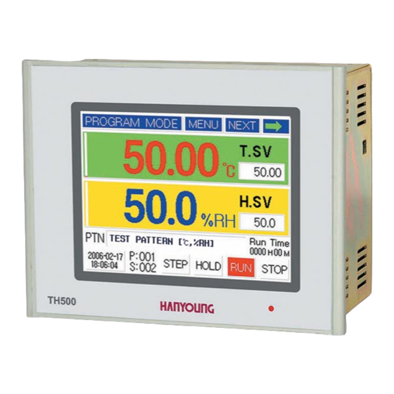
Programmable temperature and humidity controller

Advertisement

Programmable Temperature and Humidity Controller
Manual

Advertisement

Table of Contents
loading

Summary of Contents for Hanyoung TH500

  • Page 1 ● Programmable Temperature and Humidity Controller Manual...
  • Page 2: Table Of Contents

    table of contents 1.1 Checking the product 1 before starting 1.2 Safety information 1.3 Quality guarantee 2.1 How to install 2 Installation method 2.2 Suffix Code 2.3 Dimension and panel cutout 2.4 Connection diagram 2.5 Communication connection 3 Setting and operating 3.1 Initial screen 3.2 How to input 3.3 The name of each part on the operating screen...
  • Page 3 1 Before Starting Thank you for the purchase of HANYOUNG Temperature and Humidity Controller (Model# TH500/TH300). This manual contains the function of product, install method, caution information and the way of using this controller. So please read this manual before using it. And also please make this manual to be...
  • Page 4: Checking The Product

    After purchasing the product, please check for the correct model type and check for any abnormal parts/scratches on the outside. If it is incorrect model type or find any abnormal parts/scratches on the outside, please contact to our nearest sales office. 1.1.1 TH500 ⦁ Standard 1)TH500-1NN Resistance 250 Ω...
  • Page 5 2)TH500-24N I/O Board 1 Resistance 250 Ω ×2 I/O Board 2 40p cable Fixing bracket 20p cable Manual Additional Type 3)TH500-25N I/O Board 1 Resistance 250 Ω ×2 I/O Board 3 40p cable Fixing bracket 20p cable Manual Additional Type 1.1.2 TH300...
  • Page 6: Safety Information

    1.2 Safety information Alerts declared in the manual are classified to Danger, Warning and Caution by their criticality DANGER indicates an imminently hazardous situation which, if not avoided, will result in death or serious injury Danger WARNING indicates a potentially hazardous situation which, if not avoided, could result in death or serious injury Warning Caution CAUTION indicates a potentially hazardous situation which, if not avoided, may result in minor or moderate injury...
  • Page 7: Quality Guarantee

    · It has many combustible objects · It has dusts and salinity •The case of this controller is chrome-zinc plating and Bezel is made by ABS/PC anti-combustion material but please not install it to the inflammable place. Especially please do not put it on the inflammable products. •...
  • Page 8: How To Install

    2 Installation method This is information for installation place and method of TH300/TH500 temperature and humidity program controller. So please ready it before installation. 2.1 How to install (1) Use the sheet plate with thickness 1 ㎜ ~ 10 ㎜ for panel (2) Push in the temperature/humidity controller starting at the front panel (3) Mount the product by using the fixing bracket just like an image below.
  • Page 9: Suffix Code

    English / Simple Chinese Language English / Traditional Chinese Korean / Simple Chinese Korean / Traditional Chinese ※ Example of Suffix Code (Standard type : TH500-1NN / Additional type : TH500-21N) 2.2.2 TH300 Suffix Code Code Description Model Programmable Temp.& Humidity Controller / 96(W)X96(H)x100(D) ☐...
  • Page 10: Dimension And Panel Cutout

    2.3 Dimension and panel cutout 2.3.1. Type [Unit : ㎜] ●TH500-1 (Standard) 186 min ●TH500-2 (Additional ) [Unit : ㎜] 186 min...
  • Page 11 2.3.2 Separate body ● Input/Output board-1 [Unit : ㎜] Power Supply for sensor 24 V d.c 18 W max. D.I - 8 Points Connector(40 Pin) ● Output board-2 (External terminal board) [Unit : ㎜]...
  • Page 12 ● Output board-3 [Unit : ㎜] Connector(20 Pin) 2.3.3 Standard type(TH300) [Unit : ㎜]...
  • Page 13: Connection Diagram

    2.4 Connection Diagram 2.4.1 Model : TH500-1☐☐ 2.4.2 Model : TH500-2☐☐...
  • Page 14 ● Input/output board-1 ● Output board-2 Power Supply for sensor 24 V d.c 18 W max Connector(40 Pin) ● Out put board-3 Connector(20 Pin) 2.4.3 Model : TH300☐☐ Temperature Control output Humidity Communication Control output terminal Temperature retransmission out Humidity Humidity input sensor retransmission out...
  • Page 15 2.4.4 Connection method • Grounding needs more than 2 ㎜ 2 wire at least the 3rd class grounding connection (Grounding resistance : less than 100 Ω). • Please use input signal wire and output wire with shield and the shield needs to have one point grounding.
  • Page 16 ● Digital output (D.O) ■ Relay output (1c Contact) - ※ Only with TH500. ■ Relay output (1a Contact) ■ Transistor output (With TH300 D.O : 1 ~ 4)
  • Page 17 2.4.5 Digital Input (D.I) When using open collector, please use as follows : Voltage of both ends should be below 2 V and leakage current should be below 100 ㎂. ● Relay input (D.I of TH300 D.I : 1 ~ 4) ●...
  • Page 18 2.5.2 RS422/RS485 arrangement maximum 32 machines. Please contact Terminating Resistance (100 ~ 200 Ω 1/4 W) to the both of ends for retransmission lines. ● 2 Wire connection Terminating Terminating resistance resistance ● 4 Wire connection Terminating Terminating resistance resistance...
  • Page 19: Initial Screen

    When supplying the power in after completing the installation, operating screen will be displayed after the Logo display [FIG.1) screen and check [FIG.2] screen are displayed sequentially. (Users can edit the logo display screen and system check screen) TH500 TH300 [FIG.1] Logo display...
  • Page 20: How To Input

    3.2 How to input Basic setting button and input screen has the function as [Figure 1]. Input screen which is able to set necessary data on each screen will be displayed.. ⦁ [Figure 1] Setting button and Input screen Button Name Function Users can select this button on their demand.
  • Page 21 3.2.2 Number / Korean / English / sign Input Fig. 4 to 7 shows the screen for entering the Number/Korean/English/Sign. This multi-input screen enables you to enter the Number/Korean/English/Sign text respectively by pressing the turn. Its shift order is → →...
  • Page 22 Ex) If you want to indicate 1. (The _ on the bottom indicates a flickering cursor.) • Operation: • Result : 1_ Ex) If you want to indicate 123.45. (The _ on the bottom indicates a flickering cursor.) • Operation: •...
  • Page 23 Ex) If you want to indicate “ㄲ”. • Operation: • Result: ㄲ _ (The _ on the bottom indicates a flickering cursor.) Ex) If you want to indicate “가”. • Operation: • Result: 가 _ (The _ on the bottom indicates a flickering cursor.) Ex) If you want to indicate “의”.
  • Page 24 3.2.5 English Input Mode The screen for English input is shown on the Fig. 6. All the keys except the keys consist of duplicate keys. Its basic use is the same as that of the Korean input mode. Ex) If you want to indicate “B”. [Fig.
  • Page 25: The Name Of Each Part On The Operating Screen

    3.3 The name of each part on the operating screen ③ ① ② ④ ⑤ ⑫ ⑥ ⑬ ⑦ ⑭ ⑧ ⑮ ⑨ ⑯ ⑩ ⑪ ⑰ ⑱ ⑲ ⑳ [Fig. 8] Operation screen 1 for fixed control Name Name Current operation status Current date/time ①...
  • Page 26 ① ② ③ ④ ⑤ ⑪ ⑥ ⑫ ⑦ ⑬ ⑧ ⑭ ⑮ ⑨ ⑩ ⑯ ⑰ ⑱ ⑲ ⑳ ㉑ [Fig. 9] Operation screen 1 for program control Name Name Current operation status Humidity SV Up/Down indication ① ⑬ Menu button Start segment No.
  • Page 27 ④ ① ② ③ ⑤ ⑯ ⑥ ⑰ ⑱ ⑦ ⑧ ⑲ ⑨ ⑳ ⑩ ㉑ ⑪ ㉒ ⑫ ㉓ ⑬ ㉔ ⑭ ⑮ ㉕ ㉖ ㉗ [Fig.10] Operation screen 2 for program control Name Name Name Temperature/humidity up/down ① T/S status indication ㉑...
  • Page 28 ④ ① ② ③ ⑪ ⑤ ⑥ ⑫ ⑬ ⑦ ⑧ ⑭ ⑮ ⑯ ⑰ ⑨ ⑳ ㉑ ⑩ ⑱ ⑲ [Fig.11] Screen for graph indication Name Name Current temperature MV/SV indicator shift button Current operation status ① ⑫ Current temperature MV or SV indication Menu button ②...
  • Page 29: Fix Control

    3.4 Running of Fix-control Fix-control is running a temperature and humidity by fixed set value (SV). 3.4.1 Running selection of Fix-control 1. [Fig.12] Running stopped screen 1 for Fix control [Fig.13] Running screen 1 for Fix control Operation start: [FIG.12] Input the temperature set value (temperature SV) and humidity set value (humidity SV) within the fix control operation stop status screen and press the button then the fix control operation will be started just like a [FIG.13].
  • Page 30 • When it comes to temperature, its PV will be always displayed unless the sensor line is disconnected. However, as far as humidity is concerned, its PV will not be indicated unless a setting value (SV) is entered. If you set the SV to 0 and press button, you can control the temperature only.
  • Page 31 [Fig.16] Running stopped screen 1 for program control. In order to running with program control, press the button of the top on the running stopped screen 1 for program control [Fig.16] and move to the screen for function setting [Fig.17]. TH500 TH300 [FIG.17] Function setting menu...
  • Page 32 Move to the screen for with press the “Function setup 1” button, and select the program control as running method with press the button. After finish to setting for function setup 1 ~ 2 with press the button, and move to “Function setting menu”...
  • Page 33: Pid Auto-Tuning

    Once the program operation starts, buttons will appear newly like as running screen 1 for program control [Fig.21]. These buttons has function which is related to progress of segment. Button Function It stops the currently processing operation of segment and runs the next segment operation.
  • Page 34: Graph Display And Setting

    •If A/T still runs in 24 hours after A/T execution, A/T operation will come to an end automatically. If you close the A/T operation by force during A/T process, the operating value will not be saved and maintained as a previous setting value.
  • Page 35: Error Indication

    3.8 Error Indication Running screen 2 for program control or fix control [Fifg.26] is indicating an operating state for running. [Fig.26] Running screen 2 for fix control [Fig.27] Indication screen for occurrence of error The indication of errors through sensor disconnection and external D/I is displayed with button on and off in the running screen 2 for program control [Fig.
  • Page 36: Working Display

    4 Displays Entire displays are mainly composed of three sections which are Working display, Function setting display(included In program installation) and System setting display. 4.1 Operating screen After you finish to connect & turn on the power, Logo signal & System check display will be shown in a moment, and then Working display will be shown.
  • Page 37: Function Setting Display

    Function setting menu screen is shown. It is composed of 6 buttons. Push each button to set up under an item. [Fig. 35] Program control the 1st stop screen TH500 TH300 [Fig. 36] Function setting menu screen 4.3 System Setting screen...
  • Page 38 [Fig.37] Password input screen [Fig.38] System setting menu screen There is no need for System setting made separately by driver. Because the Basic setting condition of this system’ s model is set up by the operator, you should be careful especially .
  • Page 39 After finishing installation & connection, turn on the power. Logo display & System check display are shown one after other. and then [Fig.39]fix control the 1st working stop screen is displayed. [Fig.39] Fix control the 1st working stop screen TH500 TH300 [Fig.40] Function setting menu screen...
  • Page 40: Operation Setting

    5.1 Operation setting 5.1.1 Function setup 1 Pushing button in [Fig.40]Function setting menu screen, you should select or set up each setting item of the function setup 1. Choose between Select Program control and Fixed control in selecting Working method. [Fig.41] Function setup 1 screen PROGRAM Select in program control...
  • Page 41: Program Setting

    It happens that measurement value is more than setting value in initial FUZZY Over Shoot, select Fuzzy control. FUNC According to the load controlling Over shoot, the rising time can be delayed or Under Shoot can become larger in some cases. Program control Fixed control STOP...
  • Page 42 TH500 TH300 [Fig.44] Function setting menu screen [Fig.45] Program setup menu screen 5.2.1 Pattern setting Pushing button in program setup menu screen[Fig. 45] Program pattern setup screen is indicated. Set the agreeable segment of each pattern in this screen. Program control will process according to the content & sequence of segment designed.
  • Page 43 1 ~ 100 Pattern button. SEG.Page Pressing the button, it moves each 4 segment. -100~200 ℃ TH500 TEMP. SV Pressing the setting window, set Temperature SV of segment. -100~500 ℃ TH300 HUMI. SV Pressing the setting window, set Humidity SV of segment.
  • Page 44 ⇦ ➡ [Fig.49] Program Pattern Setting screen 1 [Fig.50] Program Pattern Setting screen 2 Time Signal Setting Mode is divided into 2 types according to mode : SEG On/Off Mode and Time Setting Mode. Time Signal can be set to 8 points per each Segment. [Fig.51] Time Signal Setting [Fig.52] Example of Time Signal Setting Function...
  • Page 45 ¡ Time Signal Start program Finish program operation operation [Fig. 53] Example of Time Signal ON/OFF mode Description Time Signal(T.S) T/S 1 SEG. 2 ON under 50℃ soak status SEG. 4 ON under 25℃ soak status T/S 2 T/S 3 SEG.
  • Page 46 Description Time Signal At the start point of segment 1, time signal becomes ON and after elapsing 2 hours, it will become OFF. (ON Delay : 00 h 00 m), (ON Time : 02 h 00 m) T/S 1 At the start point of segment 6, time signal becomes ON and after elapsing 2 hours, it will become OFF. (Since segment 6 is 2 hours, it only yield the output for 2 hours even if On Time is set as 3 hours) (ON Delay : 00 h 00 m), (ON Time : 03 h 00 m) At the start point of segment 1, time signal becomes ON after delaying 30 minutes...
  • Page 47 Name Function Range PTN NO. Enter the pattern number to set or select it by pressing the Up/Down button. 1~100 Pattern REPEAT Set the repeating number of pattern. 1~999 Time Set the pattern number for next operation (Operation of pattern number after completing the operation of current pattern).
  • Page 48 Section repeat setting Section repeat Start Segment operation sequence serial Repeat number ① → ② → ③ → ④ → ⑤ → ❻ → ❼ ❻ ❼ ❻ → ❼ ❷ → ❸ ❷ ❸ ❷ → ❸ → ④ →...
  • Page 49 Temp. WAIT Set the deviation range about the temperature set (0 ~ ±300) ℃(TH500) value which will be applied to the standby operation. RANGE (0 ~ ±600) ℃(TH300) Set the deviation range about the humidity set value Humi.
  • Page 50 standby time Standby standby range operation Start the standby operation because PV did not fall within the set standby range Cancel the standby operation even though PV did not fall within the set standby range because standby time is elapsed. Standby operation starts to on because PV did not fall within the standby range...
  • Page 51 Pattern alarm setting [FIG 59] screen is the setting screen that sets the alarm 1~4 which will be used within the pattern. The alarm value which was set within this screen can select the pattern alarm 1~4 of each segment. Alarm type is same as the [Table 2] alarm type and code.
  • Page 52 & humidity S.SV below. MODE S.PV Start the operation based on the current Set to the start SV upon temperature program running. (-100~200) ℃ (TH500) T. S.SV (-100~500) ℃ (TH300) Set to the start SV upon humidity program running. H. S.SV...
  • Page 53 5.2.7 Program pattern name setting [Fig.65] Program pattern name screen [Fig.66] Number input screen When pressing pattern name in the Program Pattern Name setting screen [Fig.65], Number Input Screen[Fig.66] will be shown. When pressing button in the function setting menu, Program setup menu screen will be shown.
  • Page 54: Date/Time Reservation Setting

    •Keep in mind that it is impossible to recover the original contents of the target after copying the pattern/segment. Once you press the button, the original contents of the source cannot be recovered again. After copying pattern by using button, you should make sure that the related parameter is proper setting.
  • Page 55: Graph/Save Setting

    20 seconds ~ max 216 hours according to its internal setting. If you want to use Y axis as temperature, within -100 ℃ min ~ 200 ℃ max(TH500) and -100 ℃ min ~ 500 ℃ max (TH300), you can select at least 8 ℃. In case of displaying as humidity, its value is fixed as 0 - 100 %.
  • Page 56 USB MEMORY STICK with our product name "EM310(Sold separately). ● Data transmission by USB connector TH500 present USB connection function to send saved data to PC. According to Save Sequence & Save Operation Mode set in [Fig.70] Graph Setting display, Data stored in internal memory become mass difficult to transfer with low-speedy connection (max 115,200 BPS) interface like RS232, RS422/485.
  • Page 57 [Fig.72] USB Uploader Utility value recorded in TH500 through USB.Transferred date is stored in the folder of “C:\TH500_DATA”. Because all saved Data file is in text mode, you can see the content of saved data file with any editor, word-processor or Excel. It is possible to see a graph by using Graph Viewer program presented.
  • Page 58: Sensor Type Setting

    [Fig. 75] System setup menu screen 6.1 Sensor type setting Our temperature and humidity controller (Model # TH500/TH300) support various outputs and inputs so you need to set output and input information before using this controller. On the operation screen, push screen as following, When touching button in the Operation screen, Function Setup screen will be shown up.
  • Page 59 [Fig. 76] Temperature sensor setting screen [Fig. 77] Humidity sensor setting screen (1) Sensor type Select by the input sensor type. When performing the relative humidity measurement by using the wet/dry method and when sensor for dry and wet is RTD (Pt100 Ω), please select as the for sensor type in "temperature sensor related setting"...
  • Page 60 V. Scale setting range of temperature 5.00 0.00 sensor setting screen – TH500 : -100 ~ 200℃, TH300 : -100 ~ 500℃ / Scale setting range of humidity sensor setting screen : 0.0 ~ 100.0 % (4) Sensor Bias(Input Bias) Sensor Bias screen will be displayed when touching Sensor Sensor Bias has two methods : OFF-set bias and Section bias.
  • Page 61 (5) Filter setting Filter setting sets the suitable time when process value varies due to the flow of high noise through out the input sensor line. 6.1.2 Sensor Input Setting 3 [Fig 81] Set Dry bulb temperature range and Wet/Dry Input Bias to control humidity. [FIG.81] Sensor Input Setting 3 It sets Wet bulb Temperature range.
  • Page 62: Control Output Setting

    6.1.3 Sensor Input Setting 4 Within the [FIG 82] sensor input setting 4 screen, it sets the temperature setting range, humidity setting range, temperature resolving power (decimal points indication), sensor break detection and operation delay time. [FIG.82] Sensor Input Setting 4 Setting item Explanation T.SV range...
  • Page 63 TH500 TH300 [Fig. 83] Control output setting 1 6.2.2 Control output setting 2 Humidity output type, Output period of SSR, Output direction(Reverse/Forward), Output range could be set up on the Conntrol Output Setting 2 [Fig.84] TH500 TH300 [Fig. 84] Control output setting 2...
  • Page 64 ● Control Output Setting 1 is the same as Control Output Setting 2 Select and use S.S.R or S.C.R (4 - 20 ㎃ d.c). Select according to the T.Out type equipment (Initial value : S.S.R) You can set up when you select S.S.R output. Output cycle means On/Off working time in the proportional band.
  • Page 65: Retransmission Output Setting

    6.3 Retransmission output setting Temperature & Humidity retransmission output can be selected on Control Output Setting screen 3 [Fig. 87] & Control Output Setting screen 4 [Fig. 88]. [Fig. 87] Temperature retransmission [Fig. 88] Humidity retransmission output setting screen output setting screen. ※...
  • Page 66: Inner Signal And Alarm Setting

    [Fig.89]Temperature retransmission output bias [Fig.90]Humidity retransmission output bias Button Contents Compensate overall deviations of output. Output is activated by set value on the standard output through retransmission output. Initialize bias values. 6.4 Inner Signal and Alarm setting 6.4.1 Inner Signal setup Time Signal is related with segment and Time but Inner Signal is used for signal output of temperature and humidity.
  • Page 67 Setting item Function Directly input it by pushing Inner Signal number or select it by push (I/S) Number button. (I/S) SOURCE Select Inner Signal item (Temperature or Humidity) TSV (Target Set Value): Operate base on target setting value NSV (Now Set Value): Operate base on current setting value P.V1: Operate base on process value of action range 'L' and 'H'.
  • Page 68 temp. temp. (Temp.) Section of (Temp.) temp. Up Section of Section of temp. Up temp. Hold(3 m Up Setting Up Setting Hold setting =2minute Down setting =20 ¡ (Time) (Time) Relay or (Time) O/C Output Relay or (Time) O/C Output Relay or I/S1 : Temperature PV2 operation setting O/C Output...
  • Page 69 Same as [Fig.97], range is divided by four zones (A.B.C.D) by means of L.SV, M.SV, H.SV. Its setting condition is L.SV < M.SV < H.SV Temperature Zone Description Always OFF regardless of bias(deviation) A zone (PV≥H.SV) Low limit 1) Hd=0 (Always OFF regardless of bias) B zone (M.SV≤PV≺H.SV) 2) Hd≠0 (Refer to Fig.98) OFF : PV<SV+Hd ON : PV≥SV+Hd...
  • Page 70: P.i.d Setting

    Maintain alarm on program control operation 6.5 P.I.D Setting The TH500 / 300 is equipped with the total 16 PID ZONEs. As shown in the chart below, the four temperature zones and four humidity zones are combined with each other, so you can control the temperature and humidity with the optimized PID value.
  • Page 71 [Fig.102] Temp. & Humi P.I.D Zone Setting [Fig. 103] Temp. & Humi P.I.D Setting The PID ZONE buttons on the bottom in the left side of the PID setting screen [Fig. 102] is the button for the automatic & the manual. For example, choosing if you do auto-tuning of temp.
  • Page 72 Description Range Set up proportional band. When proportional band is wide, the time to (0 ~ 100) % (TH500) reach to setting value is slow because of small quantity of control output Temp regarding the Offset When proportional band is narrow, the time to (0 ~ 600) ℃...
  • Page 73 6.6 D.I Configuration Setting D.I(Digital Input) is consisted of 3 screens .TH500 has 8 points of D.I and TH300 has 4 point of D.I (Active Low) 6.6.1 D.I Setting 1 You can assign three operation functions (RUN/STOP, STEP, HOLD) which is related to basic operation function in the D.I Setting 1[Fig.
  • Page 74 System Stop against the remaining D.I numbers except D.I numbers allocated to operation function (RUN/STOP, STEP, HOLD). D.I number When touching button, Waiting Time Input screen will be activated. When selecting Waiting Delay time, system will be finished after passing waiting delay time. TH500 TH300 [Fig. 111] D.I Setting 3...
  • Page 75 The D.O assignment is allowed to be redundant except special cases, so it is necessary to assign and enter the RELAY and O.C carefully. When outputboard-3 is used in TH500, Relay13 ~ Relay20 can be assigned through O/C1 ~ O/C8. (Example: if Relay15 is desired to be used, please set O/C3 for Relay15.) 6.7.1 D.O Configuration Setting 1(Output allocation about the innersignal)
  • Page 76 6.7.2 D.O Configuration Setting 2 (Output assignment against Time Signal) [Fig.113] D.O Configuration Setting 2 6.7.3 D.O Configuration Setting 3 It is a screen for Output assignment against T ON/OFF Signal Setting[Fig.96]. This screen is a zone assignment by means of temperature and humidity setting values. Each output according to setting condition could be set and used in the D.O Configuration Setting 3 screen.
  • Page 77 D.O Configuration Setting 4,5[Fig.115 & Fig116] is screens that functions such as alarm are allocated to real relay output and open collector output. Setting item Explanation S.Alarm 1~ 4 Assign System Alarm Output 1 ~ 4 Assign Pattern Alarm Output 1 ~ 4 P.Alarm 1~ 4 Setting item Explanation...
  • Page 78 6.7.6 D.O Configuration Setting 7 Time [FIG.118] D.O Configuration Setting 7 D.O Configuration setting 7 [FIG 118] is used when turning ON the output within the increase/maintain/decrease interval of each of temperature/humidity set value (SV). Each set input value of setting lists operates same as [FIG 119] Section of Section of Section of...
  • Page 79: Communication Setting

    Name Function Range Select the communication protocol. PCLINK operates by PCLINK /PCLINK+CRC following the format which is assigned by Hanyoung Nux and Protocol MODBUS-RTU MODBUS-RTU operates by following the standard format. Set the communication speed (BPS). You can select 9600 ~ 115,200...
  • Page 80 6.9 ETC Setting [FIG.122] ETC Setup 1 [FIG.123] ETC Setup 2 6.9.1 ETC Setup 1 Name Function Language Select a system language. It supports Korean and English. Change a system password. You should enter your password in the unit of four Password numbers and do so twice for confirmation.
  • Page 81: Input Related Setting

    ※ Select humidity sensor type as OFF in case it needs temperature control only. Limit the input range of sensor. Generally, it is fine with using the initial value but, input range of temperature is -100 ~ 200 (TH500), -100 ~ 500 (TH300) and input range of humidity is in % RH. Input...
  • Page 82 [FIG.126] Dry - Humidity sensor [FIG.127] Range setting screen correction screen 7.1.2 Correct Dry/Web bulb sensor Setting item Explanation Humi.C.RNG. Set up dry/web bulb temperature range. Dry Temp. Displays temperature of dry bulb temp. Wet Temp Displays temperature of wet bulb temp.(removal gauze) Rel.
  • Page 83 7.2 Setting Output 7.2.1 Control Output Setting TH500 TH300 [FIG.128] Control output setting 1 S.S.R or S.C.R(4 - 20 ㎃) could be used as a control output TH500 (Initial value : S.S.R) T.Out type Control output is S.S.R only. TH300 You can set up when you select S.S.R output.
  • Page 84 Explanation Setting item Select the type of RET(Retransmission output) against temperature. It is used as an input in the recorder etc. Output signal is 4 - 20 ㎃ d.c and select one among T.Source PV(Process Value),MV(Manipulated Value),SV(Setting Value). Scale value against temp. output range will be selected 4 - 20 ㎃ d.c. But if MV is T.Range selected, output will be the percentage of setting value against 4 - 20 ㎃...
  • Page 85: Fix Control

    1 screen. On this screen, press button and select fix control. And then, press button two times and move to operation screen 1 in the fix control. TH500 TH300 [FIG.133] Function setting menu...
  • Page 86 [FIG.134] Function setup 1 7.4.2 Temperature & Humidity Control Value Setting Press temp. & humidity setting and set up desired setting value. (After set up number, please press button in order to finish setting finally.) and it will be back to the 1st Operation Stop Screen of Fix Control [Fig.
  • Page 87: Program Control

    7.4.4 Start Auto Tuning Although it starts fix control operation according to usersí setting value, if you do not perform Auto Tuning, P.I.D control will be applied in accordance with its initial value at the delivery of goods. Therefore it will be better to perform Auto Tuning in order to get good control performance. To start Auto Tuning, press Auto Tuning button at the bottom of picture [Fig.136].
  • Page 88 SEG. Page Press Segment Page Shifting button( and it moves to 4 segment per each shifting MENU TH500 (-100 ~ 200) ℃ Press setting screen and set up setting value of TEMP.SV TH300 (-100 ~ 500) ℃ temperature of the segment.
  • Page 89 7.5.3 Operate and stop of program control Set the connection pattern as 1 (own number) within the pattern repetition/connection setting [FIG 140] screen. Input the each of pattern number and segment number in the program start pattern and start segment setting unit within pattern of program control operation stop [FIG 141] screen and press the button then program control operation will be started.
  • Page 90: Input

    8 Specification 8.1 Input Model TH500 TH300 R.T.D R.T.D(Resistance Temperature Detector) : Pt100Ω IEC 751 Input 0 - 5 V d.c ※ In case of using Digital Temperature Sensor (Example:EE99), please connect resistance 250 Ω in parallel on the exterior Sampling cycle 500 ㎳...
  • Page 91: Communication

    8.3 Communication Model TH300 TH500 Applicable standard EIA-RS232C, RS485/422, USB V1.1 EIA-RS232C, RS485/422 RS232C 1 : 1 connection RS485/422 max 32 devices (master included) ※address : 1 ~ 999 RS232C Communication Full duplex type RS485/422 2 wire type, 4 wire type : Half-duplex...
  • Page 92: Functions

    8.5 Functions Model TH500 TH300 Temp. : -100.00 ~ 100.00 (℃) Bias(Deviation) Humidity : -100.0 ~ 100.0 (% R.H) Dry· Wet sensor Bias After removing gauze from wet sensor, correct the difference between dry and wet sensor. Scaling Input V d.c : Input scale in accordance with conversion range...
  • Page 93: Touch Lcd

    8.6 Touch LCD TH500 TH300 Model Standard Color STN LCD 144.78 (5.7”) TFT LCD 88.9 mm(3.5”) Resolution 320 X RGB X 240 320 X RGB X 240 Life span of LED Back light (Approx. 40,000 hrs) Edge light L.E.D (Approx. 40,000 hrs)
  • Page 94: Em310 Usb Memory Storage Device

    (Sold Separately) EM310 USB Memory Storage Device •USB adaptor whose data is stored on USB memory stick after connecting between TH500/TH300 and EM310 through RS232. •Data storage device to store internal nonvolatile data in rotation without USB memory stick. 9.1 Specification...
  • Page 95 9.3 Dimension and Panel Cutout 9.4 Connection Diagram TH500 EM310 POWER 24 V d.c...
  • Page 99 HEAD OFFICE 28, Gilpa-ro 71beon-gil, Nam-gu Incheon, Korea TEL: (+82-32) 876-4697 FAX : (+82-32) 876-4696 http://www.hynux.com E-mail. overseas@hynux.com...

This manual is also suitable for:

Th300

Table of Contents