Table of Contents
Advertisement
Industrial Security Router / Firewall
Important notes
:
This document continously will be updated and completed step-by-step.
This version refers to Router firmware version 2.3.1 and above.
You may download a new version from the Weidmüller web site using the following path:
1. Open http://www.weidmueller.com/IE
2. Select section „Industrial Ethernet" „Documents"
3. Select category „Manuals"
4. Download " Manual_IE-SR-2GT-LAN-3G-UMTS_EN_Vx_yy.pdf
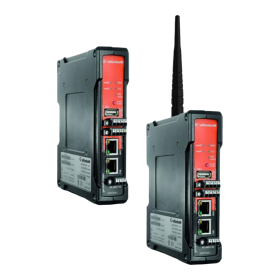
IE-SR-2GT-LAN
IE-SR-2GT-UMTS/3G
Manual
Version 1.2.4
September 2013
Advertisement
Table of Contents

Related Manuals for Weidmuller IE-SR-2GT-LAN


Summary of Contents for Weidmuller IE-SR-2GT-LAN
- Page 1 Industrial Security Router / Firewall IE-SR-2GT-LAN IE-SR-2GT-UMTS/3G Manual Version 1.2.4 September 2013 Important notes This document continously will be updated and completed step-by-step. This version refers to Router firmware version 2.3.1 and above. You may download a new version from the Weidmüller web site using the following path: 1.
-
Page 2: Copyright Notice
Industrial Security Router / Firewall IE-SR-2GT-LAN IE-SR-2GT-UMTS/3G The software described in this manual is furnished under a license agreement and may be used only in ac- cordance with the terms of that agreement. Copyright Notice Copyright 2013 Weidmüller Interface GmbH & Co. KG All rights reserved. -
Page 3: Table Of Contents
Table of Contents Industrial Security Router / Firewall ................. 1 Introduction ............................5 Proper and intended usage ......................... 5 Package Checklist ..........................5 Safety instructions ..........................6 Mounting the device.......................... 7 Technical data ........................... 8 Hardware related functional descriptions ..................11 Pin assignment of power supply connector.................. -
Page 4: Table Of Contents
B. Application scenarios (Uses cases) for VPN (Virtual private networks) ..........85 B1 - OpenVPN based remote access application via “Meeting Point” ............. 85 Description of a remote access application to allow a communication between protected, not directly accessible machine networks and remote Service-PC’s by using a public OpenVPN-Server as „Meeting-Point“... -
Page 5: Introduction
VPN-Server with other VPN devices. 2. Package Checklist Models IE-SR-2GT-LAN and IE-SR-2GT-UMTS/3G 1 x Industrial Security Router (IE-SR-2GT-LAN or IE-SR-2GT-UMTS/3G) 1 x 3-pin connector for power supply 2 x 4-pin connectors for special digital inputs and output signals (Alarm, CUT, VPN) -
Page 6: Safety Instructions
3. Safety instructions Warning - Using the selected device for purposes other than those specified or failure to observe the operating instructions and warning notes can lead to serious malfunc- tions that may result in personal injury or damage to property. - If this product malfunctions, it is no longer possible to predict the behaviour of neighbouring networked facilities and their connected devices. -
Page 7: Mounting The Device
Note - The IP protocol reserves certain IP address ranges for special purposes (such as multicasting). Do not assign IP addresses in the range from 127.0.0.0 – 127.255.255.255 or 224.0.0.0 – 255.255.255.255. - This device is intended for use in applications as described in the operating in- structions only. -
Page 8: Technical Data
DIN-rail mounting: Insert the top of the DIN-rail clip behind the upper edge of the DIN- rail (1). Then open the latch at bottom of the device by using a flat- bladed screwdriver and fix the device on the DIN-rail by gently pressing on the bottom (2). - Page 9 Can be configured as an IPsec server or client Authentication with PSK (user ID, pass- word) or X.509 certificates Hardware encryption for faster data flow IPsec rate A maximum of 64 simultaneous connec- tions (subnet with subnet or as IPsec server) Encryption algorithms DES-56, 3DES- 168, AES 128, AES 192, AES-256...
- Page 10 "VPN-active" -> Indicates an active VPN connection (24 V out) "Cut" -> Disconnects physically (link down) the WAN port (24 V In) Digital Inputs "VPN-initiate" -> Enables a pre- configured VPN connection (24 V In) Reset-Button Restore to the factory settings Power Input Voltage 1* 24 VDC (7 bis 36 Volt)
-
Page 11: Hardware Related Functional Descriptions
Warranty Period of time 3 years Order data Model name / Order number LAN/WAN Router IE-SR-2GT-LAN / 1345270000 LAN / WAN Router with integrated modem IE-SR-2GT-UMTS/3G / 1345250000 UMTS/3G 6. Hardware related functional descriptions Description of LED status indicators Signal... - Page 12 Description of device interfaces at top and front side Only model IE-SR-2GT-UMTS/3G: Connector for UMTS/3G antenna at top side Connector type: SMA female USB 2.0 connector Cut WAN port“ and „Signalize Alarm“) 4-pin connector („ UMTS/ ► 24 VDC input for Cut signal (Disabling WAN interface) and ►...
-
Page 13: Pin Assignment Of Power Supply Connector
Pin assignment of power supply connector Note: Allowed input voltage range from 7 to 36 VDC (24 VDC typical) Pin number SIGNAL NAME 24V DC Pin assignment of RJ45 Ethernet ports (LAN and WAN) SIGNAL NAME (MDI) Pin number 10/100Base T(x) 1000Base T TX + BI_DA+... -
Page 14: Pin Assignment Of Usb 2.0 Connector
Pin assignment of USB 2.0 connector The USB interface is intended for connecting peripheral devices (USB 2.0). The connector is without function in the current firmware version, but is optional for future planned applications. Pin number SIGNAL NAME Pin assignment of Smartcard Reader (ISO 7816 Standard) The integrated SIM card reader is intended for saving and restoring the configuration data. -
Page 15: Starting The Web Interface
The configuration and control of the Router is to done via the integrated Web server. Any Internet browser (Microsoft Internet Explorer or Mozilla Firefox) can be used. When delivered, the Web interface of the Router can be achieved from both LAN and WAN port. To access the Web interface of the Router the IP address of the connected PC has to be in the same logical network (IP address range) as the Router. - Page 16 Now the login prompt of the Router should appear for input „User name“ and „Password“. Default values (factory settings) for Login: User name : admin Password : Detmold Confirm your input by pressing the OK button. Note If the login prompt does not appear, please check the network LED's, if the devices are connected to the network correctly.
-
Page 17: Reset To Factory Default Settings By External Push Button
8. Reset to factory default settings by external push button By pressing the push button "Factory Default" the security Router can be reset at any time and regardless of the configuration to the default settings (factory settings). How to set the factory settings: 1. -
Page 18: Using The Weidmüller Router-Search-Utility
2. Select Downloads 3. Select Software 4. Select Industrial Ethernet 5. Download from section Industrial Security Router (Firmware and Software for IE-SR-2GT-LAN/3G/UMTS) Copyright © 2013 Weidmüller Interface GmbH & Co. KG 18 / 103 All rights reserved. Reproduction without permission is prohibited. -
Page 19: Basic Description Of The Configuration Interface (Menu Items)
Basic description of the configuration interface (menu items) The menu structure of the web Interface is divided into 4 main sections: Section Diagnostics ► Displays system status data ► Display of logging information ► Displays current interface parameters (LAN/WAN/3G) ► Feature for testing the data communication between the Router and other Ethernet devices (Ping test) Section Configuration... -
Page 20: Explanation Of The Menu Items Of Web Interface In Chronological Order
Explanation of the menu items of web interface in chronological order Figure 1: Diagnostics Systemstatus Startup screen of the web interface after login. Displays current configuration and status data. Figure 2: Diagnostics Eventlog Tab State Display events and error messages that have occurred. Copyright ©... - Page 21 Figure 3: Diagnostics Eventlog Tab Configuration Event and error messages can be sent to a syslog server (PC on the network) and also sent as emails. Figure 4: Diagnostics WAN Display of the current status of the WAN port. Figure 5: Diagnostics ...
- Page 22 Screenshot of a 3G-Router with inserted SIM Card. The Router is connected to the Internet by provider Vodafone. Figure 6: Diagnostics 3G Displays the current status of the 3G mobile connection. Figure 7: Diagnostics Ping-Test Allows sending of ICMP packets (ping) to test network connections between the Router and other Ethernet devices.
- Page 23 Figure 8: Diagnostics Remote-Capture By using the "remote capture" function data packets on both the LAN and the WAN port of the Router can be recorded for diagnostic purposes. The receiver of the diagnostic data is a PC which must have installed the tool "Wireshark".
- Page 24 Figure 10: Configuration SecureNow This is an auxiliary function for "independent learning" firewall rules based on temporary recording of data traffic. By pressing the button "Start Analysis" button the Router begins to analyze the network traffic (ports LAN, WAN and possibly UMTS/3G). As a result, the Router will provide a table showing the recorded TCP packets and protocols as well as a proposal for the setting of firewall filtering rules.
- Page 25 Figure 12: Configuration SecureNow „Analysis stopped“ Window after exiting the network analysis with a proposed indication of firewall filtering rules. If you click the button "apply rules", the firewall will be updated with the proposed rules and immediately activated. The changes are not saved automatically, so that e.g.
- Page 26 Figure 14: Configuration Packet filter Tab „Layer 2“ This is the window for the manual configuration of firewall filter rules based on Layer 2 (MAC layer). The screenshot shows the firewall settings as delivered with the 2 default rules "Allow_L2*" and „ARP*“ (Address resolution protocol).
- Page 27 Figure 16: Configuration Cut & Alarm Tab „Configuration“ In this menu it can be configured how the events "Cut" and "Alarm" - after they have occurred – will be reset (either manually by clicking on a button on the tab “State” or automatically after an elapsed time). For more information please refer to Appendix C2 (Method 2).
- Page 28 Figure 18: Configuration General settings System data Tab „Configuration“ Configuring application-related data of the Router (free text). Note: The Router has no battery-buffered, but a capacity-buffered system clock. If the Router is powered-off more than 30 minutes, the date and time values will be reset to factory default settings (Date = date of production e.g.
- Page 29 Figure 20: Configuration General settings User interface Tab „Configuration“ Setting the language (German or English) of the Web interface. Language Save and apply Setting the behaviour of the button "Activate" respectively „Save“ in the configuration windows.
- Page 30 Figure 22: Configuration General settings SCEP Tab „Configuration“ Configuration of the Router for online access to certificates which are stored on a centralized online certifica- te server (SCEP Simple Certification Enrollment Protocol). When setting up certificate-based VPN connecti- ons, the necessary certificates can be obtained directly from a SCEP server.
- Page 31 Figure 24: Configuration Access control Permissions Tab „Configuration“ Detailed assignmnet of individual rights for the created user accounts. Note: The Administrator account always has full access. It cannot be deleted. Figure 25: Configuration Access control Web access Tab „Configuration“ Select the possible access modes of the web interface (via http and / or https).
- Page 32 Figure 26: Configuration Network DNS Tab „Configuration“ Registration of up to 3 DNS servers for name resolution. The Router acts as a DNS relay server. Figure 27: Configuration Network IP Routing Tab „Configuration“ Registration of static IP routes and activating/deactivating of dynamic routing. For dynamic routing both can be selected the RIP and the OSPF protocol.
- Page 33 Figure 28: Configuration Network IP Routing Tab „State“ Display of currently valid routing table. Factory default configuration without any entry Figure 29: Configuration Network Forwarding Tab „Configuration“ Configuring standard port forwardings (IP address with port) and pure IP address forwardings. Additonally for each forwarding the feature SNAT (Source network address translation) can be activated to hide the original source.
- Page 34 Figure 31: Configuration Network 1:1 NAT Tab „Configuration“ Configuration of the mapping (assignment) of IP address ranges between LAN and WAN port, and vice- versa. For more detailed information please refer to Appendix A2. Figure 32: Configuration Network Network groups Tab „Configuration“ Creating groups with "speaking"...
- Page 35 Figure 33: Configuration Network Hardware groups Tab „Configuration“ Creating groups with "speaking" names based on MAC addresses (layer 2). A hardware group can contain any number of MAC addresses (for example, 00:15:7E:D9:09:00). Hardware groups can be used for better readability than individual MAC addresses if you will create firewall filtering rules (See menu Configuration ...
- Page 36 Screenshot of OpenVPN menu tab „Configuration“ with factory defaults (without configured OpenVPN sessions) Figure 35: Configuration VPN OpenVPN Tab „Configuration“ The OpenVPN menu allows to create and establish virtual private network connections based on the OpenVPN implementation. The Router can be configured both as OpenVPN client and OpenVPN server either based on Layer 2 (Bridging) or on Layer 3 (Routing).
- Page 37 Figure 37: Configuration VPN OpenVPN Tab „VPN2“ Screenshot of a configured OpenVPN-Server at tab VPN2. Figure 38: Configuration VPN OpenVPN Tab “State” This screenshot is displaying the status of a configured OpenVPN-Client session (L3, VPN1, currently dis- connected) and an OpenVPN-Server session (L3, VPN2, currently no connected remote clients).
- Page 38 Figure 40: Configuration VPN IPsec Tab „Configuration“ The IPsec menu allows to create and establish virtual private network connections based on the standard IPsec implementation. The Router can be configured both as IPsec client and IPsec server. IPsec allows the encryption of the complete communication flow between the Router and a remote site on IP level.
- Page 39 Figure 41: Configuration Services DHCP Server Tab „Configuration“ In operating mode "IP Router", the built-in DHCP server can be used for allocating IP addresses on both LAN-side and WAN side. By default (factory settings) the DHCP server is switched off. Note: The range of the IP addresses –...
- Page 40 Figure 42: Configuration Services Dynamic DNS Tab „Configuration“ This feature allows the Router - if connected to the Internet using dynamic IP address allocation - to be accessed by a „speaking“ name via the public Dynamic DNS service of provider „DynDNS.org“. Figure 43: Configuration ...
- Page 41 Figure 44: Configuration Services SNMP Tab „Configuration“ Activation / deactivation of the SNMP protocol (Simple Network Management Protocol). Versions v1/v2/v3 are supported. Router data can be requested using Standard MIB-II. Note: Currently no SNMP-traps are implemented. Figure 45: Configuration Services Modbus TCP Tab „Configuration“ Activation / deactivation of the integrated ModbusTCP-Server.
- Page 42 Figure 46: Configuration Services Client Monitoring Tab „Configuration“ Allows the monitoring (still alive?) of network devices via a cyclic query using the ICMP protocol (ping re- quest). As an action if a monitored Ethernet device is no longer available an „Alarm“ or a „Cut“ event can be triggered.
- Page 43 Figure 48: Configuration Prioritization LAN Tab „Configuration“ With this feature outgoing traffic on the LAN interface can be classified and prioritized. The prioritization ("traffic shaping") can be configured on both Layer 2 (based on MAC addresses) and at Layer 3 (IP addresses and protocols).
- Page 44 Figure 50: System Backup settings Tab „System“ With this menu item, the Router configuration can be stored or restored to/from the file system of the connected computer. The exported configuration file is of extension type <name>.cf2 and encrypted. Note: For creating a configuration backup file (.cf2) always the configuration currently stored in the Flash memory will be used.
- Page 45 Figure 52: System Factory defaults Tab „System“ With this menu item the Router can be set to factory default settings. Please note that doing a reset to factory values the IP addresses will be changed and the connection between the Router and the configuration PC can be lost.
- Page 46 Figure 54: System Save Tab „System“ (Screenshot of Router without SIM memory card) Figure 55: System Reboot Tab „System“ Forcing a reboot of the Router. The status message indicates whether the current configuration is saved or not. Copyright ©...
-
Page 47: A. Application Scenarios (Uses Cases) For Routing, Nat And Firewalling
A1 - Configuring the Router to connect 2 networks with different IP ad- dress ranges This Technical Note applies to the Weidmüller Industrial Router IE-SR-2GT-LAN and IE-SR-2GT-UMTS/3G Application requirements: There are 2 industrial Ethernet networks which shall be connected by the Router. Each network has its own IP address range. - Page 48 How to configure the Router Starting situation The Router is set with factory default values and can be accessed either using the LAN port by IP address 192.168.1.110 or using the WAN port by IP address 192.168.2.110. 1. Connect the configuration PC to the Router using the LAN Port (this port will be used in the example). Note: Use autonegotiation on the Ethernet Interface of the PC 2.
- Page 49 Screenshot of the default IP configuration of the Router Figure A1-2: Default values of menu IP configuration ► Configure the menu entries as following shown Operational mode: IP Router IP address parameters WAN Port: static 192.168.20.254 255.255.255.0 (Class C) NAT (masquerading) not set (leave checkbox empty) IP address parameters LAN Port: static 192.168.10.254...
- Page 50 Screenshot of Router showing the changed IP addresses Figure A1-3: Display of activated new IP addresses of LAN and WAN port 4. Change the IP address of the configuration PC according to the connected network 192.168.10.0 / 24 ► To reconnect to the Router now set the IP address of the PC to the new values IP address: 192.168.10.99 Subnet mask:...
- Page 51 5. Monitoring the currently active “routes” ► Select menu Configuration Network IP routing Tab “State” Currently active routing table Figure A1-5: Menu IP routing (Tab State) showing the new active routing table 6. Saving the new configuration ►...
- Page 52 Figure A1-7: Menu System Backup settings after saving the configuration ► Click on button “Download settings” to write the configuration file to the PC hard disk (Backup file has the default extension *.cf2”) Now the configuration of the Router is finished! Testing the accessibility between Ethernet Devices of both networks 1.
-
Page 53: A2 - Connecting 2 Ethernet Networks With Activated Nat Masquerading And Using Ip Address Forwarding
A2 - Connecting 2 Ethernet networks with activated NAT masquerading and using IP address forwarding This Technical Note applies to the Weidmüller Industrial Router IE-SR-2GT-LAN and IE-SR-2GT-UMTS/3G Application requirements: There are 2 industrial Ethernet networks which are connected by the Router. Each network has its own IP address range. - Page 54 How to configure the Router Starting situation The Router is set with factory default values and can be accessed either using the LAN port by IP address 192.168.1.110 or using the WAN port by IP address 192.168.2.110. 1. Connect the configuration PC to the Router using the LAN Port (this port will be used in the example). Note: Use autonegotiation on the Ethernet Interface of the PC 2.
- Page 55 4. Set the basic IP configuration and activate NAT masquerading ► Select menu Configuration IP configuration Screenshot of the default IP configuration of the Router Figure A2-2: Default factory settings of menu IP configuration ► Configure the menu entries as below described Operational mode: IP Router IP address parameters WAN Port:...
- Page 56 Please keep in mind that you now have lost the Router connection due to changing the IP address range of your connected LAN port. Screenshot of Router showing the changed IP addresses Figure A2-3: Display of activated new IP addresses of LAN and WAN port 5.
- Page 57 Figure A2-4: Changed settings of menu IP configuration 8. Configuring the accessibility of devices C and D of hidden network 1 ► Select menu Configuration Forwarding Figure A2-5: Empty Forwarding table of menu Forwarding ► Click icon to add a new line to enter IP forwarding values ►...
- Page 58 Figure A2-6:: Forwarding table with activated IP address forwardings Now the configuration of the Router is finished! Note: Don’t forget to save the configuration after testing. Testing the NAT masquerading feature To test the NAT masquerading function you must use the tool Wireshark on the PC which receives the ping request.
-
Page 59: A3 - Configuring The Router To Connect 2 Networks With Different Ip Address Ranges And Additional Firewall Rules
A3 - Configuring the Router to connect 2 networks with different IP ad- dress ranges and additional firewall rules This Technical Note applies to the Weidmüller Industrial Router IE-SR-2GT-LAN and IE-SR-2GT-UMTS/3G Application requirements: There are 2 industrial Ethernet networks which are connected by a Router. Each network has its own IP address range. - Page 60 How to configure the Router Starting situation The Router is set to factory default values and can be accessed either using the LAN port by IP address 192.168.1.110 or using the WAN port by IP address 192.168.2.110. 1. Connect the configuration PC to the Router using the LAN Port (this port will be used in the example). Note: Use autonegotiation on the Ethernet Interface of the PC 2.
- Page 61 Screenshot of the default IP configuration of the Router Figure A3-2: Default values of menu IP configuration ► Configure the menu entries as following shown Operational mode: IP Router IP address parameters WAN Port: static 192.168.20.254 255.255.255.0 (Class C) NAT (masquerading) not set (leave checkbox empty) IP address parameters LAN Port: static 192.168.10.254...
- Page 62 Screenshot of Router showing the changed IP addresses Figure A3-3: Display of activated new IP addresses of LAN and WAN port 4. Change the IP address of the configuration PC according to the connected network 192.168.10.0 / 24 ► To reconnect to the Router now set the IP address of the PC to the new values IP address: 192.168.10.99 Subnet mask:...
- Page 63 5. Step-by-step description of creating a new packet filter (firewall rules) to prohibit ping requests from devices of network 2 to devices B and C of network 1 General description of the Packet filter The feature „Packet filter“ can be used to create firewall rules for IP address (Layer 3) and MAC address level ( Layer 2). The packet filter is organized hierachical by using rule-sets which contains several single rules.
- Page 64 Figure A3-6: Define a new rule-set according described steps 1 to 4 Figure A3-7: Define additional parameters of the new rule-set according described steps 5 to 7 Copyright © 2013 Weidmüller Interface GmbH & Co. KG 64 / 103 All rights reserved. Reproduction without permission is prohibited.
- Page 65 Figure A3-8: Define the first rule according described steps 8 to 12 Figure A3-9: Define additional parameters of the first rule according described steps 13 to 15 Figure A3-10: Define additional parameters of the first rule according described steps 16 to 22 Copyright ©...
- Page 66 Figure A3-11: Creation of first rule completed Figure A3-12: Define of second rule according described steps 24 to 28 Figure A3-13: Define additional parameters of the second rule according described steps 29 to 31 Copyright © 2013 Weidmüller Interface GmbH & Co. KG 66 / 103 All rights reserved.
- Page 67 Figure A3-14: Define additional parameters of the second rule according described steps 32 to 38 Figure A3-15: Creation of second rule completed Figure A3-16: Setting optional date and time limitations of the rule-set Copyright © 2013 Weidmüller Interface GmbH & Co. KG 67 / 103 All rights reserved.
- Page 68 Figure A3-17: Creation of new rule-set is completed and added to the rule-set list. Move the new rule-set to top position Figure A3-18: Activate the changes Now the firewall configuration (packet filter) is finished! Copyright © 2013 Weidmüller Interface GmbH & Co. KG 68 / 103 All rights reserved.
- Page 69 Testing the result that Ethernet Devices B (192.168.10.101) and C (192.168.10.102) of network 1 cannot be “pinged” by devices of network 2 Run 3 Ping commands from a device of Ethernet network 2 (192.168.20.0/24) using below described ad- dresses (members of network 1) ...
-
Page 70: Nat Address Translation
A4 - Connecting 2 Ethernet networks with the same IP address range to another network using 1:1 NAT address translation This Technical Note applies to the Weidmüller Industrial Router IE-SR-2GT-LAN and IE-SR-2GT-UMTS/3G Application scenario: There are 2 machine networks and one upper-level production network. Each machine network is connected to the pro- duction network by a security Router. - Page 71 This document describes an application scenario using 3 Routers. But for a simple test of the feature “1:1 NAT” you only need 1 Router (configured as Router 1 of machine network 1). In this case use 2 devices (PC’s or what- ever) to simulate one member of “machine network”...
- Page 72 In this example Router 3 of the production network is to be configured with 2 static IP routes pointing to networks 1 and 2 that Ethernet devices behind Router 1 and Router 2 (connected at LAN port) can find each other. As an alternative all Routers can be configured to use dynamic IP routing (either RIP or OSPF or both) to announce their connected networks to the other Routers automatically without configuring static routes at Router 3 manually.
- Page 73 4. Set the basic IP configuration ► Select menu Configuration IP configuration Screenshot of the default IP configuration of the Routers Figure A4-2: Default values of menu IP configuration ► Configure the menu entries as following shown Only for Router 1 Operational mode: IP Router IP address parameters WAN Port:...
- Page 74 192.168.21.254 255.255.255.0 (Class C) NAT (masquerading) not set (leave checkbox empty) Default gateway 172.16.1.254 (Router of the production network) Only for Router 3 Operational mode: IP Router IP address parameters WAN Port: static 10.1.1.254 255.255.0.0 (Class B) NAT (masquerading) not set (leave checkbox empty) IP address parameters LAN Port: static 172.16.1.254...
- Page 75 For reconnecting Router 3 you also can chose e.g. IP address 172.16.1.100 (subnet mask 255.255.0.0) but you have to change the cable connection from WAN to LAN port due to the fact that Router 3 is connected to the production network by LAN port (see network diagram).
- Page 76 Screenshot of Router 1 Figure A4-5: New values of menu IP configuration 6. Configuring 1:1 NAT address translation (Do this only for Routers 1 and 2) ► Select menu Configuration Network 1:1 NAT Screenshot of Router 1 Figure A4-6: Default values of menu 1:1 NAT configuration Copyright ©...
- Page 77 Configure below described entries on both Routers 1 and 2 in the section LAN: of the “1:1 NAT configuration menu”. ► Activate parameter “Enable 1:1 NAT” Click on checkbox ► Private IP address/subnet mask: 192.168.1.254/24 Note: No further settings have to be done (Do not activate checkbox “Advanced settings”) ►...
- Page 78 From the perspective of an addressed receiver in the production network the sender has always the public IP address. 7. Configuring static routes (Only for Router 3, skip if you test the”Ssimple scenario” with only 1 Router) Next 2 static routes have to be configured on Router 3 that all Ethernet devices of machine networks networks 1 and 2 (behind LAN port of Routers 1 and 2) can get access to each other.
- Page 79 ►Click button “Add entry” to add the new static route to the routing table. Values for the second route: ● Destination network: 192.168.21.0 (Public address range of machine network 2 at LAN port of Router 2) ● Subnet mask: 24 (Class C) ●...
- Page 80 9. Saving the new configuration ► Select menu System Save This symbol starts flashing if the configuration has been changed and activated but not saved. Clicking on the icon the web interface jumps into this menu item (regardless which window is currently displayed) Figure A4-11: Menu System ...
- Page 81 Testing the configured feature 1:1 NAT 1. Testing the accessibility between an Ethernet device of machine network 1 and an Ethernet device of produc- tion network (“Simple scenario” if you have only 1 Router for testing) Note: You can use a PC for simulating an Ethernet device (machine) of networks 1. Use a second PC to be a member of the production network.
-
Page 82: A5 - Using Dynamic Ip Routing As An Alternative For Manually Configuring Static Routes
A5 - Using dynamic IP routing as an alternative for manually configuring static routes Instead of configuring static routes on Router 3 it is more comfortable to use the “dynamic IP routing” feature to an- nounce the routes of all Router network interfaces to each Router. For announcing the routing information the protocols RIP or OSPF can be used. - Page 83 Configure below described entries in the section Dynamic routing of the menu: Configure the below described parameters for all Routers 1, 2 and 3 LAN: ● Type: Select “RIP” ● Simple password: Free text Note: If there are several Routers with activated RIP but only the Routers 1, 2 and 3 should exchange their routing tables, then you have to use the same password for each Router.
- Page 84 Figure A5-3: Menu IP routing (Tab State) showing the new active routing table Testing the accessibility between Ethernet Devices of network 1 and 2 1. Send a ping request from Machine 1 of Network 1 to Machine 1 of Network 2 Send “ping 192.168.21.100”...
-
Page 85: B. Application Scenarios (Uses Cases) For Vpn (Virtual Private Networks)
B. Application scenarios (Uses cases) for VPN (Virtual private networks) B1 - OpenVPN based remote access application via “Meeting Point” Description of a remote access application to allow a communication be- tween protected, not directly accessible machine networks and remote Ser- vice-PC’s by using a public OpenVPN-Server as „Meeting-Point“... -
Page 86: C. Additional Application Notes
C. Additional application notes C1- How to start and stop a pre-defined OpenVPN connection by exter- nal 24 VDC input In this example a pre-defined OpenVPN client connection (at tab VPN1) will be configured to be started and stopped by external 24 VDC input. C1.1 Go into the Web-Interface and select OpenVPN menu. - Page 87 Click “Apply settings” C1.6 To activate the “not permanent” configured OpenVPN connection provide 2 pins of the 4-pin con C1.7 nector named “VPN initiate / VPN active” with 24 VDC. If you disconnect the power then the VPN tunnel will be closed. See below described pin assigment.
-
Page 88: C2- Description How To Disable The Ethernet Connection At Wan Port
Output Input key signal Start /Stop VPN active External 24 VDC C2- Description how to disable the Ethernet connection at WAN port The Ethernet WAN port can physically disabled using several methods: Method 1: Hardware-based disconnection (Cut) by external digital input Method 2: Software-based disconnection by a Firewall-rule Method 3: Software-based disconnection by feature “Client monitoring”... - Page 89 Output Input signal Disconnect Alarm event WAN port External 24 VDC Method 2: Software-based disconnection of WAN port by Firewall-rule Inside of a Firewall-rule it can be configured that the WAN port will be disconnected if this Firewall-rule matches. As an example below we create a Firewall-rule which will deactivate the WAN port if a device is sending a ping request incoming into the WAN port and outgoing to a device connected at the LAN port.
- Page 90 Click button “Next” C2.4 C2.5 Select Inbound Interface = WAN Click button “Add” to create the first rule of the rule-set “Disconnect_WAN” C2.6 Enter * in both fields “Source IP address” and “Destination IP address” C2.7 C2.8 Select IP protocol = ICMP Click button “Next”...
- Page 91 C2.12 Select “Action” = Cut + Drop C2.13 Enable checkboxes Log and Alarm to signalize a CUT in the Event-Log and to switch-on the Alarm-LED at frontside of the Router C2.14 Enter the name of the rule (max. 15 characters) C2.15 Click button “Next”...
- Page 92 C2.18 Click button “Close” to finish the rule-set creation Now the new rule-set Disconnect_WAN will be displayed in the Layer3-Filter-table. We need to change the position of the new rule-set to top-most cause the Packet filter (Firewall) checks the rules from top to bottom. Due to the fact that the default filter rule “Allow_L3”...
- Page 93 C2.19 Change the position of rule-set “Disconnect_WAN” to be the topmost by clicking the arrow-icon C2.20 Click button “Apply settings” to activate the new firewall-filter Important: Before testing the CUT function we have to determine how to re-activate a disconnected WAN port. This has to be done in the menu Cut &...
- Page 94 C2.22 Set the modes for CUT and Alarm acknowledgement to Automatic After finishing configuration and applying (don’t forget) of the behaviour how to re-set the event, a test of the configured CUT-Firewall-rule can be started. C2.23 Connect a PC at WAN-Port of the Router. C2.24 Connect a second PC at LAN-Port of the Router to check what happens when the CUT-event is triggered.
- Page 95 Click button “Add entry” C3.3 Click button “Apply settings” to activate the new entry C3.4 Note: The behaviour of re-setting a triggered (CUT or Alarm) depends on the configuration of the menu Configuration Cut & Alarm. Additionally, if the parameter “Enable automatic client monitoring recovery acknowledgment” is activated then the Router will automatically re-activate the WAN port if the monitored device (at LAN port) is accessible again (cause the Router is still checking every 50 seconds by ping request).
-
Page 96: C3- Description How To Use The Feature "Remote Capture" With Wireshark To Analyze The Lan/Wan Traffic Of The Router
C3- Description how to use the feature “Remote Capture” with Wire- shark to analyze the LAN/WAN traffic of the Router The function “Remote Capture” can be used to record the traffic at Router’s LAN- or WAN port using a re- mote connected PC running Wireshark. - Page 97 Click button “Options” C3.4 Click button “Manage Interfaces” and change to tab “Remote Interfaces” C3.5 Copyright © 2013 Weidmüller Interface GmbH & Co. KG 97 / 103 All rights reserved. Reproduction without permission is prohibited.
- Page 98 Click button “Add” C3.6 Enter into field “Host” the IP address of the Router C3.7 Note: You can enter either the IP address of LAN or WAN port. The import fact is that the Routers IP ad- dress is accessible by the Wireshark-PC. Enter into field “Port”...
- Page 99 In this example we want to capture the traffic at WAN port. C3.11 Double-Click the line rpcap//[172.16.1.20]:2002/WAN Click button “Remote Settings” C3.12 Clear the checkbox “Do not capture own RPCAP traffic” C3.13 Click button “OK” C3.14 Again click button “OK” to close the window “Edit Interface Settings” C3.15 Copyright ©...
- Page 100 C3.16 Activate the checkbox in line rpcap//[172.16.1.20]:2002/WAN Click button “Start” to record the traffic at Routers WAN port C3.17 Copyright © 2013 Weidmüller Interface GmbH & Co. KG 100 / 103 All rights reserved. Reproduction without permission is prohibited.
-
Page 101: C4- Description How To Configure The Internet Access Of A Pc Via A 3G Router
C4- Description how to configure the Internet access of a PC via a 3G Router This description applies to the Weidmüller Industrial Router IE-SR-2GT-UMTS/3G Illustration of the application scenario 3G connection IP: 192.168.1.99 parameters provided by Subnet: 255.255.255.0 UMTS / 3G 3G provider Standard gateway: 192.168.1.110 3G Router... - Page 102 C4.3 Start a Web browser and login into the Router Web interface (http://192.168.1.110) User: admin Password: Detmold Figure C2: Login page of the Router (equivalent with menu Diagnostics System State) C4.4 Configure the 3G connection ► Select menu Configuration IP configuration ►...
- Page 103 ► Click button “Apply settings” to activate the new settings. Now the Router tries to connect to the Internet. Please wait some seconds. C4.5 Evaluating a successful Internet connection ► Select menu Diagnostics Event The event log displays the result of initiating the 3G Internet connection. Figure C4: Screenshot of event log ►...
Need help?
Do you have a question about the IE-SR-2GT-LAN and is the answer not in the manual?
Questions and answers