Table of Contents
Advertisement
Quick Links
Ethernet Switch – Premium Line
IE-SW-PL18M Series (Managed)
Hardware Installation Guide
Fourth Edition, October 2012
1243410000/03/10.12
Please note:
This document, the detailed manual and any further
product information - if available - can be
downloaded at the internet link:
http://www.weidmueller.com/downloads
Copyright Notice
Copyright
2012 Weidmüller Interface GmbH & Co. KG
All rights reserved.
Reproduction without permission is prohibited.
Advertisement
Table of Contents

Related Manuals for Weidmuller IE-SW-PL18M-2GC-16TX


Summary of Contents for Weidmuller IE-SW-PL18M-2GC-16TX
- Page 1 Ethernet Switch – Premium Line IE-SW-PL18M Series (Managed) Hardware Installation Guide Fourth Edition, October 2012 1243410000/03/10.12 Please note: This document, the detailed manual and any further product information - if available - can be downloaded at the internet link: http://www.weidmueller.com/downloads Copyright Notice Copyright 2012 Weidmüller Interface GmbH &...
-
Page 2: Package Checklist
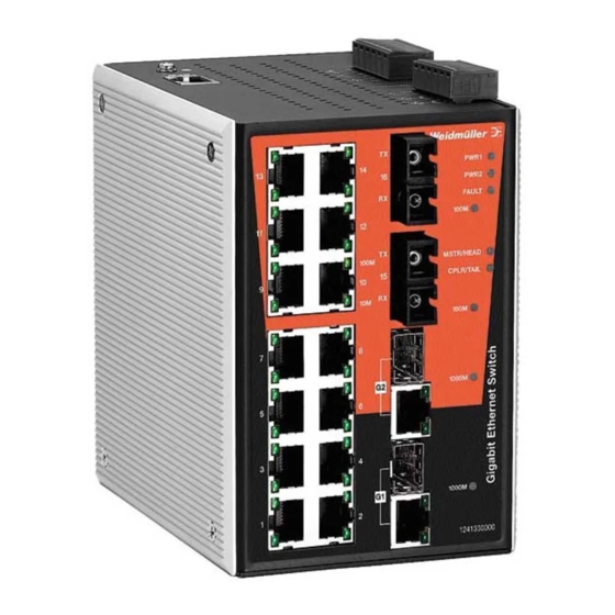
Package Checklist Your Ethernet Switch is shipped with the following items. If any of these items are missing or damaged, please contact your Weidmüller customer service for assistance. 1 Ethernet Switch IE-SW-PL18M Hardware Installation Guide CD-ROM with User’s Manual and Windows Utility (option) ... - Page 3 Panel Views of IE-SW-PL18M-2GC-16TX Grounding screw Console port Heat dissipation orifices 6-pin terminal block for DI 1, DI 2, and PWR 2 6-pin terminal block for PWR1 Relay 1, and Relay 2 10/100BaseT(X), ports 1 to 16 PWR 1: LED for power input 1...
- Page 4 Panel Views of models IE-SW-PL18M-2GC-14TX2ST IE-SW-PL18M-2GC-14TX2SC IE-SW-PL18M-2GC-14TX2SCS NOTE: The appearance of models IE-SW-PL18M-2GC14TX2SCS, IE-SW-PL18M-2GC14TX2SC and IE-SW-PL18M-2GC14TX2ST are - apart from the optical connectors - identical. Grounding screw Console port Heat dissipation orifices 6-pin terminal block for DI 1, DI 2, and PWR 2 6-pin terminal block for PWR1 Relay 1, and Relay 2...
-
Page 5: Mounting Dimensions (Unit = Mm)
Mounting Dimensions (unit = mm) DIN-Rail Mounting The aluminum DIN-Rail attachment plate should already be fixed to the back panel of IE-SW-PL18M when you take it out of the box. If you need to reattach the DIN-Rail attachment plate to IE-SW-PL18M, make sure the stiff metal spring is situated towards the top, as shown by the following figures. -
Page 6: Atex Information
ATEX Information 1. Certification number DEMKO 11 ATEX 150191X 2. Ambient range (-40°C ≤ Tamb ≤ 75°C) 3. Certification string (Ex nC IIC T4) 4. Standards covered ( EN60079-0:2006, EN60079-15:2005) 5. The conditions of safe usage: The Ethernet Communication Devices are to be mounted in an IP54 enclosure and used in an area of not more than pollution degree 2 as defined by IEC60664-1. -
Page 7: Wiring The Relay Contact
You should also pay attention to the following points: Use separate paths to route wiring for power and devices. If power wiring and device wiring paths must cross, make sure the wires are perpendicular at the intersection point NOTE: Do not run signal or communications wiring and power wiring through the same wire conduit. -
Page 8: Wiring The Redundant Power Inputs
Wiring the Redundant Power Inputs IE-SW-PL18M-Switches have two sets of power inputs - power input 1 and power input 2 – located on the 6-pin terminal block connector on the top panel of the device. See sketch below how to connect. STEP 1: Insert the negative/positive DC wires into the V-/V+ terminals, respectively. - Page 9 Cable Wiring—Diagrams labeled “Cable Wiring” present standard cable wiring schemes for cables used to connect Ethernet Switch ports to other devices. These diagrams display three pieces of information: When building your own cable, refer to the “pin-to-pin” Cable Wiring information displayed between the two vertical dashed lines to see which pin of the connector on the left should be connected to which pin of the connector on the right.
-
Page 10: 10/100Baset(X) Ethernet Port Connection
RJ45 (10-pin) to DB9 (F) Cable Wiring Server RJ45 (10-pin) to DB25 (F) Cable Wiring Server 10/100BaseT(X) Ethernet Port Connection The 10/100BaseT(X) ports located on the Switch´s front panel are used to connect to Ethernet-enabled devices. Most users will choose to configure these ports for Auto MDI/MDI-X mode, in which case the port’s pinouts are adjusted automatically depending on the type of Ethernet cable used (straight-through or cross-over), and the type of device (NIC-type or... -
Page 11: 100Basefx Ethernet Port Connection
RJ45 (8-pin, MDI-X) Port Pinouts Signal RJ45 (8-pin) to RJ45 (8-pin) Straight-through Cable Wiring RJ45 (8-pin) to RJ45 (8-pin) Cross-over Cable Wiring 100BaseFx Ethernet Port Connection The concept behind the SC/ST port and cable is quite straightforward. Suppose you are connecting devices I and II. As opposed to electrical signals, optical signals do not require a circuit in order to transmit data. -
Page 12: Led Indicators
ATTENTION This is a Class 1 Laser/LED product. To prevent damage to your eyes, do not stare directly into the laser beam. LED Indicators The front panel of IE-SW-PL18M Series contains several LED indicators. The function of each LED is described in the following table: Color State Description... -
Page 13: Specifications
(TP) Blinking Data is being transmitted at 100 Mbps. TP port’s 100 Mbps link is inactive. TP/SFP port’s 1000 Mbps link is active. Blinking Data is being transmitted at 1000 Mbps. 1000M GREEN (TP/SFP) TP/SFP port’s 1000 Mbps link is inactive. - Page 14 [50/125 μm, 800 MHz*km] cable d. [62.5/125 μm, 500 MHz*km] cable e. [9/125 μm, 3.5 PS/(nm*km)] cable Power Input Voltage 24 VDC (12 to 45 VDC), redundant inputs Input Current (@24V) 0.51A: IE-SW-PL18M-2GC-16TX 0.61A: IE-SW-PL18M-2GC14TX2SC/2ST/2SCS Connection Two removable 6-pin terminal blocks Overload Current Protect. Present Reverse Polarity Protection Present...
- Page 15 Storage Temperature -40 to 85°C (-40 to 185°F) Ambient Relative Humidity 5% to 95% (non-condensing) Regulatory Approvals Safety UL60950-1, UL 508 CSA C22.2 No. 60950-1, EN60950-1 Hazardous Location UL/cUL Class I, Division 2, Groups A, B, C, and D, ATEX, Zone 2, Ex nC IIC FCC Part 15, CISPR (EN55022) class A EN61000-4-2 (ESD), Level 2 EN61000-4-3 (RS), Level 3...
Need help?
Do you have a question about the IE-SW-PL18M-2GC-16TX and is the answer not in the manual?
Questions and answers