Table of Contents
Advertisement
Ethernet Switch – Value Line
IE-SW-VL16 Series
Hardware Installation Guide
Sixth Edition, October 2012
1243330000/05/10.12
Please note:
This document and any further product information - if
available - can be downloaded at the internet link:
http://www.weidmueller.com/downloads
Copyright Notice
Copyright 2012 Weidmüller Interface GmbH & Co. KG
All rights reserved.
Reproduction without permission is prohibited.
Advertisement
Table of Contents

Related Manuals for Weidmuller IE-SW-VL16-16TX


Summary of Contents for Weidmuller IE-SW-VL16-16TX
- Page 1 Ethernet Switch – Value Line IE-SW-VL16 Series Hardware Installation Guide Sixth Edition, October 2012 1243330000/05/10.12 Please note: This document and any further product information - if available - can be downloaded at the internet link: http://www.weidmueller.com/downloads Copyright Notice Copyright 2012 Weidmüller Interface GmbH & Co. KG All rights reserved.
-
Page 2: Package Checklist
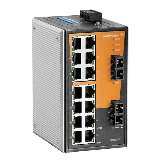
Overview The IE-SW-VL16 Series of 16-port smart Ethernet switches provides an economical solution for your Ethernet connections. As an added bonus, the built-in smart alarm function helps system maintainers monitor the health of your Ethernet network. IE-SW-VL16 Series has an operating temperature range of 0 to 60°C (Standard models) or optional a extended operating temperature range from -40 to 75°C and is designed to withstand a high degree of vibration and shock. - Page 3 Panel Layout of IE-SW-VL16-16TX 1. Grounding screw 2. Terminal block for power input (PWR1, PWR2) and relay output 3. Heat dissipation orifices 4. DIP switches (IE-SW-VL16 Series has 18 DIP switches in total; 2 DIP switches are reserved) 5. Power input PWR1 LED 6.
- Page 4 Panel Layout of IE-SW-VL16-14TX-2SC (SC-type) and IE-SW-VL16-14TX-2ST (ST-type) NOTE: The appearance of models IE-SW-VL16-14TX-2SC and IE-SW-VL16-14TX-2ST are - apart from the optical connectors - identical. 1. Grounding screw 2. Terminal block for power input (PWR1, PWR2) and relay output 3. Heat dissipation orifices 4.
-
Page 5: Mounting Dimensions (Unit = Mm)
Mounting Dimensions (unit = mm) DIN-Rail Mounting The aluminum DIN-Rail attachment plate should already be fixed to the back panel of IE-SW-VL16 Series when you take it out of the box. If you need to reattach the DIN-Rail attachment plate, make sure the stiff metal spring is situated towards the top, as shown in the figures below. -
Page 6: Atex Information
ATEX Information 1. Certificate number DEMKO 11 ATEX 150191X 2. Ambient range (-40°C ≤ Tamb ≤ 75°C) 3. Certification string (Ex nC nL IIC T4) 4. Standards covered (EN60079-0:2006, EN60079-15:2005) 5. The conditions of safe usage: These products must be mounted in an IP54 enclosure. ... - Page 7 WARNING Safety First! Be sure to disconnect the power cord before installing and/or wiring your Ethernet Switch. Calculate the maximum possible current in each power wire and common wire. Observe all electrical codes dictating the maximum current allowable for each wire size. If the current goes above the maximum ratings, the wiring could overheat, causing serious damage to your equipment.
-
Page 8: Wiring The Alarm Contact
Wiring the Alarm Contact The Alarm Contact consists of the two middle contacts of the terminal block on Ethernet Switch top panel. You may refer to the next section for detailed instructions on how to connect the wires to the terminal block connector, and how to attach the terminal block connector to the terminal block receptor. -
Page 9: Communication Connections
Communication Connections IE-SW-VL16 models have 14 or 16 10/100BaseT(X) Ethernet ports, and 2 or 0 (zero) 100BaseFX (SC/ST-type connector) fiber ports. 10/100BaseT(X) Ethernet Port Connection The 10/100BaseT(X) ports located on the front panel are used to connect to Ethernet-enabled devices. Below we show pinouts for both MDI (NIC-type) ports and MDI-X (HUB/Switch-type) ports, and also show cable wiring diagrams for straight-through and cross-over Ethernet cables. -
Page 10: 100Basefx Ethernet Port Connection
100BaseFX Ethernet Port Connection The concept behind the SC/ST port and cable is very straightforward. Suppose you are connecting devices I and II. Contrary to electrical signals, optical signals do not require a circuit in order to transmit data. Consequently, one of the optical lines is used to transmit data from device I to device II, and the other optical line is used transmit data from device II to device I, for full-duplex transmission. -
Page 11: Dip Switch Settings
DIP Switch Settings IE-SW-VL16 Series DIP Switches ON: Enables the corresponding PORT Alarm. If the port’s link fails, the relay will form an open circuit and the fault LED will light up. Off: Disables the corresponding PORT Alarm. The relay will form a closed circuit and the Fault LED will never light up. -
Page 12: Auto Mdi/Mdi-X Connection
Auto MDI/MDI-X Connection The Auto MDI/MDI-X function allows users to connect 10/100BaseTX ports to any kind of Ethernet device, without needing to pay attention to the type of Ethernet cable being used for the connection. This means that you can use either a straight-through cable or cross-over cable to connect IE-SW-VL16 switches to other Ethernet devices. -
Page 13: Switching, Filtering, And Forwarding
Switching, Filtering, and Forwarding Each time a packet arrives at one of the switched ports, a decision is made to either filter or forward the packet. Packets with source and destination addresses belonging to the same port segment will be filtered, constraining those packets to one port, and relieving the rest of the network from the need to process them. - Page 14 (Core/Cladding) μm 50/125 9/125 (1 dB/km, 800 MHz km) Power Input Voltage 12 to 45 VDC, redundant inputs Input Current @ 24VDC 0.27 A: IE-SW-VL16-16TX 0.44 A: IE-SW-VL16-14TX-2SC/ST Connection Removable “6-pin” Terminal Block Overload Current 1.6 A Protection Reverse Polarity...
-
Page 15: Contact Information
WARRANTY 5 years Weidmüller gives a 5 year warranty on this product in accordance with the warranty terms as described in the general conditions of sale of the Weidmüller company which has sold the products to you. Weidmüller warrants to you that such products the defects of which have already existed at the time when the risk passed will be repaired by Weidmüller free of charge or that Weidmüller will provide a new, functionally equivalent product to replace the defective one.
Need help?
Do you have a question about the IE-SW-VL16-16TX and is the answer not in the manual?
Questions and answers