Table of Contents
Advertisement
Quick Links
Advertisement
Table of Contents

Related Manuals for Digi Connect IT 16


Summary of Contents for Digi Connect IT 16
- Page 1 Digi Connect IT® 16/48 User Guide User Guide...
- Page 2 Information in this document is subject to change without notice and does not represent a commitment on the part of Digi International. Digi provides this document “as is,” without warranty of any kind, expressed or implied, including, but not limited to, the implied warranties of fitness or merchantability for a particular purpose.
-
Page 3: Table Of Contents
Contents Digi Connect IT® 16/48 User Guide Connect IT 16 and 48 key features Get started with Connect IT 16/48 Verify product components Included equipment Required additional equipment Optional additional equipment Optional equipment Cellular ONLY: Insert the CORE module Prerequisites... - Page 4 Download an archive of the supported MIBs Download a support report file Configure and view events and logs in the web UI View events information Configure log messages from the web UI View system log information Digi Connect IT® 16/48 User Guide...
- Page 5 Download a support report Hardware Front panel and LEDs Back panel and LEDs Hardware specifications Power supply Electrical rating Mounting options Regulatory and safety information Safety warnings Power supply and supplemental fan module considerations Information access Digi Connect IT® 16/48 User Guide...
-
Page 6: Digi Connect It® 16/48 User Guide
Dual Gigabit Ethernet and Dual SFP+ option for robust flexible network connectivity. Devices with either 16 or 48 serial connections to manage IT assets via console port. Option to install Certified Digi Cellular CORE Module to support different cellular speeds with modules certified for specific regions. -
Page 7: Get Started With Connect It 16/48
Get started with Connect IT 16/48 This section explains what comes with each Connect IT model, how to install the necessary software, and how to connect the hardware. Verify product components. Cellular ONLY: Insert the CORE module. Connect the power supplies and fans. -
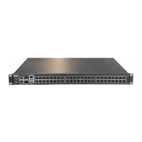
Page 8: Verify Product Components
Connect IT Digi Connect IT Note This image is of Connect IT 48. The Connect IT 16 has a blank panel instead of ports 17 - 48. For detailed information about the front and back panels, see Connect IT 16/48 hardware and LEDs. -
Page 9: Required Additional Equipment
Description Each kit includes three items: two power supply items and one fan Power supply kit item. These items are connected to the Connect IT 16/48. See Connect the power supplies and fans. You can choose between the following two kits: ITPS-PSEK: Connect IT 16/48 power supply kit, port-side exhaust. -
Page 10: Optional Equipment
Get started with Connect IT 16/48 Cellular ONLY: Insert the CORE module Equipment Description Antennas (2) Optional equipment Equipment Description IEC 60320 power cord. Power cord An additional power cord used for redundancy. Cellular ONLY: Insert the CORE module Note If you are connecting to a network using an Ethernet connection, you can skip this section. -
Page 11: Connect The Power Supplies And Fans
The thumb screws used to connect the items to the Connect IT are blue. ITPS-PSIK: Connect IT 16/48 power supply kit, port-side intake. Use this when the serial ports will be in the cold aisle. The thumb screws used to connect the items to the Connect IT are red. -
Page 12: Optional: Connect Sfp+ Modules
Get started with Connect IT 16/48 Optional: Connect SFP+ modules 3. Connect the second power supply and fan unit to the Connect IT. a. Orient the second power supply and fan unit to match the picture shown above. b. Insert the unit into the slot on the right side of the device. -
Page 13: Connect Hardware And Connect To A Cellular Network
The second power cord can also be plugged in, but it is not required. It is available for power redundancy. 3. Plug the power supply unit into an AC power outlet to power up the Connect IT 16/48. Digi Connect IT® 16/48 User Guide... -
Page 14: Connect Equipment To The Connect It Serial Ports
Signal name Console port and DTE mode DCE mode Signals are not used in DCE mode. Signals are not used in DCE mode. GND/DCD Signals are not used in DCE mode. Signals are not used in DCE mode. Digi Connect IT® 16/48 User Guide... -
Page 15: Configure Connect It Using Remote Manager
Before you begin You must create a Remote Manager account add your Connect IT devices to your Remote Manager inventory. Note For more detailed information about using Remote Manager, see the Digi Remote Manager User Guide. Digi Connect IT® 16/48 User Guide... -
Page 16: Create A Remote Manager Account And Add Devices
Note Create a Remote Manager account for instructions on how to create an account. 1. In a web browser, type https://remotemanager.digi.com. 2. Type your login credentials in the Username and Password fields. Note If you have forgotten your credentials, click Forgot Username or Password and follow the online instructions. -
Page 17: Update The Firmware On Connect It From Remote Manager
4. From the list of devices, click on the Connect IT for which you want to update the firmware. 5. In the toolbar, click More > Update Firmware. The Update Firmware dialog appears. 6. Click Browse to select the firmware file you just downloaded. Digi Connect IT® 16/48 User Guide... -
Page 18: View Identifying Information About The Connect It On The Home Page
As an alternative, click Properties in the toolbar and then from the Home page, click Edit Device Configuration. 6. The configuration Home page appears, and shows basic identification and version information about the selected Connect IT. Digi Connect IT® 16/48 User Guide... -
Page 19: Schedule System Maintenance From Remote Manager
10:00 and 12:00. Log into your Remote Manager account. Access the Remote Manager configuration page. 3. Click Config > System in the toolbar. The System page appears. 4. Expand the Schedule Tasks section. Digi Connect IT® 16/48 User Guide... - Page 20 Daily: The device runs the modem firmware check and update once a day within the given time window. Weekly: The device runs the modem firmware check and update any day within the given time window only once during the week. Digi Connect IT® 16/48 User Guide...
-
Page 21: Configure Vpn Using Remote Manager
Expand the advanced section. b. In the NAT keep alive time field, enter the length of time to keep NAT alive for IPSEC tunnels. the default is 40 seconds. The syntax for the entry is number {w|d|h|m|s}. Digi Connect IT® 16/48 User Guide... -
Page 22: Configure An Openvpn Server From Remote Manager
Click the plus sign icon to define a client. The Add OpenVPN client dialog appears. d. Enter a client name in the field. e. Click OK. 7. Click Apply at the top of the screen to save the changes. Digi Connect IT® 16/48 User Guide... -
Page 23: Configure An Ip Tunnel For A Vpn From Remote Manager
View Connect IT summary dashboard Remote Manager tracks connection history between a Connect IT and Remote Manager. You can a graph of the connection information. See View Connect IT connection history for detailed information. Digi Connect IT® 16/48 User Guide... -
Page 24: View Connect It Connection History
3. From the list of devices, click on the Connect IT for which you want to view connection history. 4. Click Properties in the toolbar. The Home page for the Connect IT appears. 5. Click Connection History in the left pane. The connection history displays. Digi Connect IT® 16/48 User Guide... -
Page 25: Configure Connect It Using The Web User Interface
Synchronize system time from the web UI View Connect IT status information Download an archive of the supported MIBs Download a support report file Configure and view events and logs in the web UI Digi Connect IT® 16/48 User Guide... -
Page 26: Log In To The Connect It Web Ui
4. In the Idle timeout field, enter the length of time after which users are disconnected from services. Leave this field blank to disable this feature. Syntax: number{w|d|h|m|s} 5. Click Save at the bottom of the screen to save the changes. Digi Connect IT® 16/48 User Guide... -
Page 27: Add A New User From The Web Ui
Log in to the Connect IT web 2. Click Configuration in the left pane. 3. Expand the Authentication section. 4. Expand the Groups section. Digi Connect IT® 16/48 User Guide... - Page 28 From the Tunnel list box, select the appropriate tunnel. Nagios access When selected, allows members of this group to query the device for service status for Nagios. 7. Click Save at the bottom of the screen to save the changes. Digi Connect IT® 16/48 User Guide...
-
Page 29: Change A Connect It Password From The Web Ui
Connect IT. The methods are attempted in the list order until the first successful authentication result is returned. A user fails authentication when no method succeeds. Log in to the Connect IT web 2. Click Configuration in the left pane. 3. Expand the Authentication section. Digi Connect IT® 16/48 User Guide... -
Page 30: Update Connect It Firmware
4. In the Filter the list box, enter Connect IT. As you type, matches display. 5. Click Connect IT. 6. From the list of options, select the option for your model: Connect IT 16 or Connect IT 48. 7. From the Firmware Updates section, select the version you want to download. The file is downloaded to a folder on your computer. -
Page 31: Configure Connection To Remote Manager From The Web Ui
Select the Enable central management option to enable Connect IT to connect to Remote Manager. b. From the Service list box, select the Digi Remote Manager option. c. In the Management server field, enter the URL for Remote Manager. d. In the Retry interval field, enter the interval at which Connect IT should attempt to connect to Remote manger, after a disconnect. - Page 32 These commands are removed from the data stream and are not sent to the equipment connected to the serial port. If left blank, the escape sequence is disabled. The default is a tilde (~). An entry is optional. Digi Connect IT® 16/48 User Guide...
-
Page 33: Monitor Serial Port Changes
Log in to the Connect IT web 2. Click Configuration in the left pane. 3. Expand the Serial section. 4. Expand the port that you want to configure: Port 1, Port 2, Port 3, or Port 4. Digi Connect IT® 16/48 User Guide... -
Page 34: Enable A Tcp Connection On The Serial Port
Log in to the Connect IT web 2. Click Configuration in the left pane. 3. Expand the Serial section. 4. Expand the port that you want to configure: Port 1, Port 2, Port 3, or Port 4. Digi Connect IT® 16/48 User Guide... -
Page 35: Enable An Ssh Connection On The Serial Port
Log in to the Connect IT web 2. Click Configuration in the left pane. 3. Expand the Serial section. 4. Expand the port that you want to configure: Port 1, Port 2, Port 3, or Port 4. Digi Connect IT® 16/48 User Guide... -
Page 36: Configure The Modem In The Connect It
Configure the modem You can configure the modem in the Connect IT. Log in to the Connect IT web 2. Click Configuration in the left pane. 3. Expand the Modem section. 4. Configure the settings. Digi Connect IT® 16/48 User Guide... - Page 37 Match SIM by list box. Enter the SIM slot match criteria. The interface is applied when the modem is using this SIM slot. Modems with a single SIM slot will always match SIM1. The default value is SIM1. Digi Connect IT® 16/48 User Guide...
- Page 38 In normal operation, this field should be blank. Roaming Enable roaming to allow connections to data services outside of the original country of the SIM. When enabled, the cost of data use may increase significantly. Digi Connect IT® 16/48 User Guide...
-
Page 39: Define A Custom Apn
You can define a list of custom APNs to try when connecting to the cellular network. Log in to the Connect IT web 2. Click Configuration in the left pane. 3. Expand the APN list section. Digi Connect IT® 16/48 User Guide... -
Page 40: Configure An Ip Passthrough For The Modem
Enable firewall packet filtering rules for the passthrough network traffic. If this setting is disabled, then network traffic is allowed in both directions, and it is the responsibility of the external device to provide its own firewall. Digi Connect IT® 16/48 User Guide... -
Page 41: Configure A Custom Gateway For The Modem
2. Click Configuration in the left pane. 3. Expand the Modem section. 4. Expand the Custom gateway section. 5. Configure the settings. Setting Description Enable Select Enable to enable a custom gateway for this network interface. Digi Connect IT® 16/48 User Guide... -
Page 42: Configure An Ipv4 Network Interface For The Modem
If there are multiple active default routes with the same metric, then connections will be load-balanced between the default routes in proportion to their weight. Default: 10 Minimum: 1 Maximum: 65535 Digi Connect IT® 16/48 User Guide... -
Page 43: Configure An Ipv6 Network Interface For The Modem
Log in to the Connect IT web 2. Click Configuration in the left pane. 3. Expand the Modem section. 4. Expand the IPv6 section. 5. Configure the settings. Setting Description Enable Select Enable to enable an IPv4 network interface. Digi Connect IT® 16/48 User Guide... -
Page 44: Configure The Network From The Web Ui
Configure the network from the web UI You can configure the network for the Connect IT. Log in to the Connect IT web 2. Click Configuration in the left pane. 3. Expand the Network section. Digi Connect IT® 16/48 User Guide... -
Page 45: Configure Vpn From The Web Ui
Configure an IPsec tunnel for a VPN from the web UI You can configure an IPsec tunnel for a VPN. Log in to the Connect IT web 2. Click Configuration in the left pane. 3. Expand the VPN section. 4. Expand the IPsec section. Digi Connect IT® 16/48 User Guide... -
Page 46: Configure An Openvpn Server From The Web Ui
Complete the fields in each of the sections. To display information about what you should enter in each field, click the down arrow and then Help next to each field. 7. Click Save at the bottom of the screen to save the changes. Digi Connect IT® 16/48 User Guide... -
Page 47: Configure An Ip Tunnel For A Vpn From The Web Ui
5. Click Choose File to select a configuration file that was previously backed 6. Browse for and select the file. The file name appears in the page. 7. Click Restore Config to copy the configuration from the file to the Connect IT. Digi Connect IT® 16/48 User Guide... -
Page 48: Delete The Connect It Configuration
5. Click Save at the bottom of the screen to save the changes. Configure services from the web UI You can configure services for the Connect IT. Log in to the Connect IT web 2. Click Configuration in the left pane. 3. Expand the Services section. Digi Connect IT® 16/48 User Guide... -
Page 49: Monitor The Data From The Connect It
4. Each sub-section enables you to configure a different monitoring method. Expand the sub- section and complete the fields in each of the sections. To display information about what you should enter in each field, click the down arrow and then Help next to each field. Digi Connect IT® 16/48 User Guide... -
Page 50: Configure The Find Me Feature
Probe network traffic on this device and export statistics to NetFlow collectors. Device Health Device Health is a system monitor that collects and stores metrics over a period to time and reports them to Digi Remote Manager. intelliFlow Reserved for future use. -
Page 51: Schedule System Maintenance From The Web Ui
If this field is empty, maintenance is not scheduled and no maintenance tasks will run. Syntax: HH:MM If the duration in the Duration window field is set to 1 or more hours, the minutes field is truncated. Digi Connect IT® 16/48 User Guide... - Page 52 Complete the fields in each of the sections. To display information about what you should enter in each field, click the down arrow and then Help next to each field. 7. Click Save at the bottom of the screen to save the changes. Digi Connect IT® 16/48 User Guide...
-
Page 53: Synchronize System Time From The Web Ui
Log in to the Connect IT web 2. Select the System tab in the left pane. 3. Scroll down to the SNMP MIBs section. 4. Click Download MIBs. The .zip archive file is downloaded to your downloads folder. Digi Connect IT® 16/48 User Guide... -
Page 54: Download A Support Report File
You can configure the log messages for the Connect IT. Log in to the Connect IT web 2. Click Configuration in the left pane. 3. Expand the System section. 4. Expand the Log section. Digi Connect IT® 16/48 User Guide... -
Page 55: View System Log Information
Critical messages: Only critical messages appear. These display in red text. Warning messages: Only warning messages appear. These display in blue text. Info messages: Only informational messages appear. These display in black text. Debug messages: Only debugging messages appear. These display in gray text. Digi Connect IT® 16/48 User Guide... -
Page 56: Troubleshooting
Troubleshooting Reset your device to the factory defaults Tips for improving cellular signal strength Download a support report Digi Connect IT® 16/48 User Guide... -
Page 57: Reset Your Device To The Factory Defaults
If the signal strength LEDs or the signal quality for your device indicate Poor or No servcie, try the following things to improve signal strength: If available, connect a different set of antennas. Purchase a Digi Antenna Extender Kit: Antenna Extender Kit, 1 Download a support report You can download a support report from the device to provide to technical support. -
Page 58: Front Panel And Leds
When starting up, the WWAN Signal, WWAN Service, and Status LEDs on the back of the Connect IT also flash. Solid blue: The Connect IT initialization is complete. Red: The Connect IT has had start-up failure. Digi Connect IT® 16/48 User Guide... - Page 59 Left: The left LED for a port lights yellow. Right: The right LED for a port lights green. Behaviors: ON, OFF, slow blink, fast blink. USB ports Connect a USB flash drive to the Connect IT for backup or logging. Digi Connect IT® 16/48 User Guide...
-
Page 60: Back Panel And Leds
See Connect equipment to the Connect IT serial ports. Connect IT 16: serial ports 1-16. Connect IT 48: serial ports 1-48. The LED on the left lights: Yellow: There is activity on the port. - Page 61 Off: No power is connected to the PS2 power supply. Solid blue: Power is connected to the PS2 power supply and is in use by the Connect IT. Flashing blue: Power is connected to the PS2 power supply, but is it unusable. Digi Connect IT® 16/48 User Guide...
-
Page 62: Hardware Specifications
0° C - 50° C Power supply The Connect IT 16 or 48 must be operated only with power supplies from a Digi-provided power supply kit, either ITPS-PSIK (for Port Side Air Intake) or ITPS-PSIK (for Port Side Air Exhaust), as appropriate for the device installation location. -
Page 63: Mounting Options
NEMA locking connector, 18 AWG. Mounting options Install the Connect IT device on a 19" rack using the provided rack mount ears. If necessary, the ears can be moved to the rear side of the device. Digi Connect IT® 16/48 User Guide... -
Page 64: Regulatory And Safety Information
Regulatory and safety information Safety warnings Review the following safety warnings for Connect IT 16/48. WARNING! Notice the following safety warnings: Risk of explosion if battery is replaced by incorrect battery type. Dispose of used batteries according to the instructions. -
Page 65: Power Supply And Supplemental Fan Module Considerations
Manuals and further information are provided. Warning messages for replacing batteries and for restricted access area requirements are available in this manual. See Safety warnings. The Digi Connect IT® 16/48 User Guide is accessible online. Digi Connect IT® 16/48 User Guide...
Need help?
Do you have a question about the Connect IT 16 and is the answer not in the manual?
Questions and answers