Table of Contents
Advertisement
Quick Links
Download this manual
See also:
User Manual
Advertisement
Table of Contents

Related Manuals for Digi Connect IT 16


Summary of Contents for Digi Connect IT 16
- Page 1 Digi Connect IT® 16/48 User Guide User Guide...
- Page 2 Information in this document is subject to change without notice and does not represent a commitment on the part of Digi International. Digi provides this document “as is,” without warranty of any kind, expressed or implied, including, but not limited to, the implied warranties of fitness or merchantability for a particular purpose.
-
Page 3: Table Of Contents
Contents Digi Connect IT® 16/48 User Guide Connect IT 16 and 48 key features Get started with Connect IT 16/48 Verify product components Included equipment Required additional equipment Optional additional equipment Optional equipment Cellular ONLY: Insert the CORE module Prerequisites... - Page 4 Access the Terminal screen Access help Save your changes Log in to the Connect IT local web user interface Manually configure PC to connect to the Connect IT Log in to Remote Manager and access the Configuration screen Digi Connect IT® 16/48 User Guide...
- Page 5 Download a support report Hardware Front panel and LEDs Back panel and LEDs Hardware specifications Power supply Electrical rating Mounting options Regulatory and safety information Safety warnings Power supply and supplemental fan module considerations Information access Digi Connect IT® 16/48 User Guide...
-
Page 6: Digi Connect It® 16/48 User Guide
Dual Gigabit Ethernet and Dual SFP+ option for robust flexible network connectivity. Devices with either 16 or 48 serial connections to manage IT assets via console port. Option to install Certified Digi Cellular CORE Module to support different cellular speeds with modules certified for specific regions. -
Page 7: Get Started With Connect It 16/48
Get started with Connect IT 16/48 This section explains what comes with each Connect IT model, how to install the necessary software, and how to connect the hardware. Verify product components. Cellular ONLY: Insert the CORE module. Connect the power supplies and fans. -
Page 8: Verify Product Components
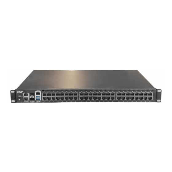
Connect IT Digi Connect IT Note This image is of Connect IT 48. The Connect IT 16 has a blank panel instead of ports 17 - 48. For detailed information about the front and back panels, see Connect IT 16/48 hardware and LEDs. -
Page 9: Required Additional Equipment
Description Each kit includes three items: two power supply items and one fan Power supply kit item. These items are connected to the Connect IT 16/48. See Connect the power supplies and fans. You can choose between the following two kits: ITPS-PSEK: Connect IT 16/48 power supply kit, port-side exhaust. -
Page 10: Optional Equipment
Get started with Connect IT 16/48 Cellular ONLY: Insert the CORE module Equipment Description Antennas (2) Optional equipment Equipment Description IEC 60320 power cord. Power cord An additional power cord used for redundancy. Cellular ONLY: Insert the CORE module Note If you are connecting to a network using an Ethernet connection, you can skip this section. -
Page 11: Connect The Power Supplies And Fans
The thumb screws used to connect the items to the Connect IT are blue. ITPS-PSIK: Connect IT 16/48 power supply kit, port-side intake. Use this when the serial ports will be in the cold aisle. The thumb screws used to connect the items to the Connect IT are red. -
Page 12: Optional: Connect Sfp+ Modules
Get started with Connect IT 16/48 Optional: Connect SFP+ modules 3. Connect the second power supply and fan unit to the Connect IT. a. Orient the second power supply and fan unit to match the picture shown above. b. Insert the unit into the slot on the right side of the device. -
Page 13: Connect Hardware And Connect To A Cellular Network
The second power cord can also be plugged in, but it is not required. It is available for power redundancy. 3. Plug the power supply unit into an AC power outlet to power up the Connect IT 16/48. Digi Connect IT® 16/48 User Guide... -
Page 14: Connect Equipment To The Connect It Serial Ports
Serial connector pinout. You must use a cable with an RJ45 connector to connect to the Connect IT 16/48 with a RJ45, DB9F or DB9M connector, as determined by your device type, to terminate to your device. Consult the user guide for the device you are connecting to the Connect IT to determine the connector type, cable type, and pinout positions for your specific device. -
Page 15: Configure The Connect It 16/48
Configure the Connect IT 16/48 You can configure the Connect IT 16/48 in either web UI method: the local web user interface or Remote Manager. Once you have selected a web UI option and logged in, the features and page layout are the same in both the local web user interface and Remote Manager. -
Page 16: Change A Connect It Password
Configure the Connect IT 16/48 Change a Connect IT password Change a Connect IT password You can change either the root password or the user password for the Connect IT. Log in to manage the Connect IT. Access the Configuration > Authentication screen. -
Page 17: Create A User Profile And Assign An Access Control Group
Configure the Connect IT 16/48 Manage users and groups Log in to manage the Connect IT. Access the Configuration > Authentication screen. 3. Expand the Groups section. 4. Expand the group that you want to configure: admin, serial, or a user group that you have added. -
Page 18: Configure Two-Factor Authentication For A User
Configure the Connect IT 16/48 Update the firmware on the Connect IT Log in to manage the Connect IT. Access the Configuration > Authentication screen. 3. Expand the Users section. 4. Click Add or + to add a new user name. -
Page 19: Update The Firmware On Connect It From Remote Manager
4. In the Filter the list box, enter Connect IT. As you type, matches display. 5. Click Connect IT. 6. From the list of options, select the option for your model: Connect IT 16 or Connect IT 48. 7. From the Firmware Updates section, select the version you want to download. The file is downloaded to a folder on your computer. -
Page 20: Configure Idle Timeout
Configure the Connect IT 16/48 Configure idle timeout 4. You can add additional methods. a. Click Add or +. The new row is immediately added to the list of methods. b. From the Method list box, select the method that you want to use for authentication: Local users: Authenticate using the users defined with the configuration. -
Page 21: Configure Remote Power Management
Configure the Connect IT 16/48 Configure Remote Power Management Configure Remote Power Management The remote power management feature allows you control outlets on a power controller using serial or network interfaces. As you manage a device which is connected to a serial port on the Connect IT, you can also control the power outlets you have associated with that serial port. - Page 22 Configure the Connect IT 16/48 Configure Remote Power Management 7. The entries in the following fields must match the information for the power controller. Refer to your power controller manual for the correct entries: Baud rate, Data bits, Parity, Stop bits, and Flow control.
-
Page 23: Create An Access Control Group For Power Management And Assign To Users
Configure the Connect IT 16/48 Configure Remote Power Management 9. Configure the outlets on the power controller that can be controlled by the port. a. Click Outlets to expand the outlet section. Define an outlet on the power controller. In the Add Outlet field, enter a name for the outlet and then click Add. -
Page 24: View Power Controller Status And Manage Power (Administrators)
The state of the power for each outlet is displayed: on: The outlet has power. off: The outlet does not have power. unknown: The Connect IT 16/48 cannot get a status from the power controller. Change the power state You can change the power state for an outlet. -
Page 25: Configure A Serial Port
Configure the Connect IT 16/48 Configure a serial port 4. Information about the port you are connected to, as well as commands. Connecting to port3: PowerManPort3 Settings: 9600, 8, 1, none, none Type '~.' to disconnect from port Type '~?' to list commands 5. - Page 26 Configure the Connect IT 16/48 Configure a serial port Setting Description Serial mode Select an access mode for this serial port. Login: Select this option to display the Login Manger screen when you access the web UI. Remote access: Select this option to allow remote management.
-
Page 27: Monitor Serial Port Changes
Configure the Connect IT 16/48 Configure a serial port Setting Description Escape sequence The sequence of characters used to start an escape sequence. Escape sequences allow a user to send control commands to the serial port interface. These commands are removed from the data stream and are not sent to the equipment connected to the serial port. -
Page 28: Enable A Telnet Connection On The Serial Port
Configure the Connect IT 16/48 Configure a serial port Setting Description Select the CTS option to monitor CTS changes on this port. Select the DCD option to monitor DCD changes on this port. 6. Click Save or Apply. Enable a Telnet connection on the serial port You can enable a Telnet connection on the serial port. -
Page 29: Enable A Tcp Connection On The Serial Port
Configure the Connect IT 16/48 Configure a serial port Setting Description Interfaces Expand the Interfaces section to add network interfaces from which this serial port can be accessed. Click Add to add an interface. Zones Expand the Zones section to add firewall zones from which this serial port can be accessed. -
Page 30: Enable An Ssh Connection On The Serial Port
Configure the Connect IT 16/48 Configure a serial port Setting Description Interfaces Expand the Interfaces section to add network interfaces from which this serial port can be accessed. Click Add to add an interface. Zones Expand the Zones section to add firewall zones from which this serial port can be accessed. -
Page 31: Configure A Modem
Configure the Connect IT 16/48 Configure a modem 7. Click Save or Apply. Configure a modem You can enable a modem in the Connect IT and configure the modem to enable gateways and network interfaces. Configure the modem You can configure the modem in the Connect IT. - Page 32 Configure the Connect IT 16/48 Configure a modem Setting Description Match SIM by The match criteria to apply when determining if this interface should be used. Any SIM: Apply this interface to the modem with any SIM. SIM slot: Apply this interface when a specified SIM slot is active.
- Page 33 Configure the Connect IT 16/48 Configure a modem Setting Description Match IMSI This conditional field displays when the IMSI option is selected from the Match SIM by list box. Enter the IMSI (International Mobile Subscriber Identity) match criteria. The interface is applied when the SIM card has this IMSI.
-
Page 34: Define A Custom Apn List
Configure the Connect IT 16/48 Configure a modem Setting Description SIM failover alternative The action to perform when the connection retries have been exceeded but no other SIM is available to switch to. None: Perform no alternative action. Reset modem: Reset the modem if the SIM failover feature is not enabled and thus automatic SIM switching is not available. -
Page 35: Configure A Custom Gateway For The Modem
Configure the Connect IT 16/48 Configure a modem 7. From the APN version list box, select the IP version for which the modem may request addresses. 8. From the Authentication method list box, select the authentication method used to connect to the cellular network. -
Page 36: Configure An Ipv6 Network Interface For The Modem
Configure the Connect IT 16/48 Configure a modem Setting Description Metric The priority of routes associated with the network interface. If there are multiple active routes that match a destination, then the route with the lowest metric will be used. -
Page 37: Configure The Network
Configure the Connect IT 16/48 Configure the network Setting Description Enable Select Enable to enable an IPv4 network interface. Metric The priority of routes associated with the network interface. If there are multiple active routes that match a destination, then the route with the lowest metric will be used. -
Page 38: Configure The Connect It Name From The Local Web User Interface
Configure the Connect IT 16/48 Configure the Connect IT name from the local web user interface 3. Each sub-section enables you to configure a different network type. Expand the sub-section and complete the fields in each of the sections. To display information about what you should enter in each field, hover over the field name or click the down arrow and then Help next to each field. -
Page 39: Configure A Vpn
Configure the Connect IT 16/48 Configure a VPN Field Description Name The name for the Connect IT. This name displays in prompts and log messages. Contact Contact information for this Connect IT. This is for reference only. Location A description of the Connect IT's physical location. This is for reference only. -
Page 40: Configure An Ip Tunnel For A Vpn
Configure the Connect IT 16/48 Back up, restore, and delete the configuration Log in to manage the Connect IT. Access the Configuration > VPN screen. 3. Expand the OpenVPN section. 4. Define an OpenVPN server. a. Expand the OpenVPN section. -
Page 41: Back Up The Connect It Configuration
Configure the Connect IT 16/48 Configure the firewall Back up the Connect IT configuration From the System page in the local web user interface, you can back up the Connect IT configuration file and save it to your PC. You can then use that file to... -
Page 42: Configure Services
Configure the Connect IT 16/48 Configure services Section Description Zones Configure the groups of network interfaces that can be referred to by packet filtering rules and access control lists. Port forwarding Configure a list of port forwarding rules. These rules allow network connections to the Connect ITto be forwarded to other servers by translating the destination address. -
Page 43: Monitor The Data From The Connect It
Probe network traffic on this device and export statistics to NetFlow collectors. Device Health Device Health is a system monitor that collects and stores metrics over a period to time and reports them to Digi Remote Manager. intelliFlow Reserved for future use. -
Page 44: Immediately Reboot The Connect It From The Local Web User Interface
You can also choose to schedule a daily reboot. See Schedule a reboot from the local web user interface. 1. In a web browser, type https://remotemanager.digi.com. 2. Type your login credentials in the Username and Password fields. 3. Click Log in. -
Page 45: Schedule System Maintenance
Configure the Connect IT 16/48 Schedule system maintenance Schedule system maintenance You can schedule the system to run a set of system maintenance tasks to run within a specified time window. You can also schedule a custom script to run at the specified time and frequency. -
Page 46: Synchronize System Time
Configure the Connect IT 16/48 Synchronize system time Field Description Frequency The frequency at which the modem firmware check and update tasks will run. The default value is Daily. Daily: The device runs the modem firmware check and update once a day within the given time window. -
Page 47: View Connect It Status Information
Configure the Connect IT 16/48 View Connect IT status information 5. Specify the NTP servers used to synchronize the time on the Connect IT. a. Expand the NTP servers section. b. In the Server field, enter the name of the NTP server that is used to synchronize the time. -
Page 48: Configure And View Events And Logs
Configure the Connect IT 16/48 Configure and view events and logs Configure and view events and logs You can configure and view events and log messages for a Connect IT. View events information In the Events page in the local web user interface, you can view detailed information about events that have occurred. -
Page 49: View System Log Information
Configure the Connect IT 16/48 Configure and view events and logs View system log information In the System Logs page in the local web user interface, you can view detailed debugging, warning, and critical messages. Log in to the Connect IT local web user interface. -
Page 50: Work With The Web Ui (Web User Interface)
Work with the web UI (web user interface) You can access and configure your Connect IT 16/48 from a web UI (web user interface). Two web UI options are available: Local web user interface: You can access the local web UI by connecting to the Connect IT and logging in to the device. -
Page 51: Access The Terminal Screen
Log in to the Connect IT local web user interface You can log in to your Connect IT 16/48 using the local web user interface on the device. To be able to access the local web user interface, your PC and the Connect IT must be connected by an Ethernet cable. -
Page 52: Manually Configure Pc To Connect To The Connect It
1. Select the Properties of the relevant network connection on the Windows PC. 2. Click the Internet Protocol Version 4 (TCP/IPv4) parameter. 3. Click Properties. The Internet Protocol Version 4 (TCP/IPv4) Properties dialog appears. Digi Connect IT® 16/48 User Guide... -
Page 53: Log In To Remote Manager And Access The Configuration Screen
After you have created your Remote Manager account, you can log in. Note Create a Remote Manager account for instructions on how to create an account. 1. In a web browser, type https://remotemanager.digi.com. 2. Type your login credentials in the Username and Password fields. Digi Connect IT® 16/48 User Guide... - Page 54 Click Try Remote Manager 3.0 preview in the top right of the screen. b. Click Devices in the left pane. c. Double-click on the device you want to configure. d. Click the Edit Configuration button. Digi Connect IT® 16/48 User Guide...
-
Page 55: Troubleshooting
Troubleshooting Reset your device to the factory defaults Tips for improving cellular signal strength Download a support report Digi Connect IT® 16/48 User Guide... -
Page 56: Reset Your Device To The Factory Defaults
If the signal strength LEDs or the signal quality for your device indicate Poor or No servcie, try the following things to improve signal strength: If available, connect a different set of antennas. Purchase a Digi Antenna Extender Kit: Antenna Extender Kit, 1 Download a support report You can download a support report from the device to provide to technical support. -
Page 57: Front Panel And Leds
When starting up, the WWAN Signal, WWAN Service, and Status LEDs on the back of the Connect IT also flash. Solid blue: The Connect IT initialization is complete. Red: The Connect IT has had start-up failure. Digi Connect IT® 16/48 User Guide... - Page 58 Left: The left LED for a port lights yellow. Right: The right LED for a port lights green. Behaviors: ON, OFF, slow blink, fast blink. USB ports Connect a USB flash drive to the Connect IT for backup or logging. Digi Connect IT® 16/48 User Guide...
-
Page 59: Back Panel And Leds
See Connect equipment to the Connect IT serial ports. Connect IT 16: serial ports 1-16. Connect IT 48: serial ports 1-48. The LED on the left lights: Yellow: There is activity on the port. - Page 60 Off: No power is connected to the PS2 power supply. Solid blue: Power is connected to the PS2 power supply and is in use by the Connect IT. Flashing blue: Power is connected to the PS2 power supply, but is it unusable. Digi Connect IT® 16/48 User Guide...
-
Page 61: Hardware Specifications
0° C - 50° C Power supply The Connect IT 16 or 48 must be operated only with power supplies from a Digi-provided power supply kit, either ITPS-PSIK (for Port Side Air Intake) or ITPS-PSIK (for Port Side Air Exhaust), as appropriate for the device installation location. -
Page 62: Mounting Options
NEMA locking connector, 18 AWG. Mounting options Install the Connect IT device on a 19" rack using the provided rack mount ears. If necessary, the ears can be moved to the rear side of the device. Digi Connect IT® 16/48 User Guide... -
Page 63: Regulatory And Safety Information
Regulatory and safety information Safety warnings Review the following safety warnings for Connect IT 16/48. WARNING! Notice the following safety warnings: Risk of explosion if battery is replaced by incorrect battery type. Dispose of used batteries according to the instructions. -
Page 64: Power Supply And Supplemental Fan Module Considerations
Manuals and further information are provided. Warning messages for replacing batteries and for restricted access area requirements are available in this manual. See Safety warnings. The Digi Connect IT® 16/48 User Guide is accessible online. Digi Connect IT® 16/48 User Guide...
Need help?
Do you have a question about the Connect IT 16 and is the answer not in the manual?
Questions and answers