Table of Contents
Advertisement
Quick Links
Advertisement
Table of Contents

Related Manuals for Digi Connect DC-ES-4SB


Summary of Contents for Digi Connect DC-ES-4SB
- Page 1 ® Digi Connect Device Server Hardware setup guide...
-
Page 2: Customer Support
Information in this document is subject to change without notice and does not represent a commitment on the part of Digi International. Digi provides this document “as is,” without warranty of any kind, expressed or implied, including, but not limited to, the implied warranties of fitness or merchantability for a particular purpose. -
Page 3: Table Of Contents
Environmental information Symbol definitions Cautions and warnings Connectors, LEDs, and controls Setting up Digi Connect ES Device Server hardware Before setting up the hardware EMC specification Setting up Digi Connect ES hardware Digi Connect ES Device Server Hardware setup guide... - Page 4 Digi Connect ES Device Server Hardware setup guide...
-
Page 5: About Digi Connect Es Device Server
Digi Connect ES 8SB with Switch (8 ports) Digi Connect ES products are compliant with IEC 60601-1 3rd edition. Digi Connect ES is intended for use as an ITE device for data transmission only. No data modification takes place within the device. -
Page 6: Additional Information
0.2A max Fuse 250V F1A Additional information All Digi Connect ES Device Server models include software in the form of firmware described in the Digi Connect Family User Guide. Go to www.digi.com/products/ serialservers/digiconnectes to get the latest version of the guide, as well as a detailed product datasheet for the Digi Connect ES family of products. -
Page 7: Symbol Definitions
Catalog number Caution Conforms to the European Medical Device Directive 93/42/EEC; self certified Consult instructions for use Date of manufacture YYYY Ethernet connection Functional earth terminal Fuse High voltage Humidity limitation Manufacturer Digi Connect ES Device Server Hardware setup guide... -
Page 8: Cautions And Warnings
Clean and disinfect the device periodically by wiping the outer case with a lint-free cloth, lightly moistened with warm water and a mild, non-abrasive cleaning solution or 70% isopropyl alcohol. • Do not use excessive pressure when wiping. • Do not sterilize the device server. Digi Connect ES Device Server Hardware setup guide... -
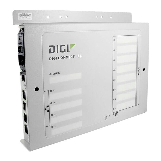
Page 9: Connectors, Leds, And Controls
Connectors, LEDs, and controls Callout Symbol Description Fuse 250V F1A Off/On Mains power connector/Power input 100-240V 50 - 60 Hz, 0.2A MAX Grounding stud Ethernet uplink port Reset switch Ethernet switch ports Ethernet uplink LED Digi Connect ES Device Server Hardware setup guide... - Page 10 Connectors, LEDs, and controls Callout Symbol Description Ethernet switch LED Serial LED Find me locater LED Power LED Serial ports (4 or 8) Digi Connect ES Device Server Hardware setup guide...
-
Page 11: Setting Up Digi Connect Es Device Server Hardware
EMC specifications below. EMC specification Guidance and manufacturer's declaration - electromagnetic emissions The customer or the user of the Digi Connect ES should assure that the device is used in an environment that meets EMC specifications. Emissions test... -
Page 12: Setting Up Digi Connect Es Hardware
(5) to the network. The LED (8) illuminates if the connection is active and blinks if data is transmitted. • Ethernet port 1 for hub or switch: On SW models, to connect the Digi Connect ES to a hub or switch, use Ethernet port 1. Digi Connect ES Device Server Hardware setup guide... - Page 13 Digi Connect ES Device Server Ethernet ports. 5 Connect serial devices: Connect each serial device to a serial port (13) on the Digi Connect ES Device Server. If the connection between the device and the network is established, the serial port LED (10) illuminates.
- Page 14 © 2014 Digi International. All rights reserved.
Need help?
Do you have a question about the Connect DC-ES-4SB and is the answer not in the manual?
Questions and answers