
Related Manuals for ProSoft MVI56E-FLN


Summary of Contents for ProSoft MVI56E-FLN
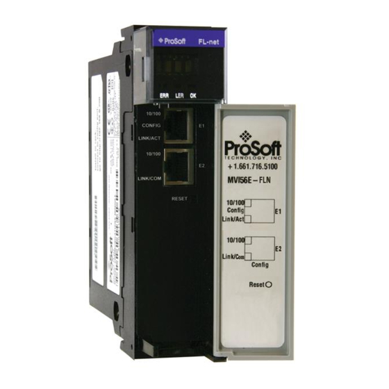
- Page 1 MVI56E-FLN ControlLogix Platform FA Control Network Ethernet Communication Module July 10, 2019 USER MANUAL...
-
Page 2: Your Feedback Please
® ProSoft Technology Product Documentation In an effort to conserve paper, ProSoft Technology no longer includes printed manuals with our product shipments. User Manuals, Datasheets, Sample Ladder Files, and Configuration Files are provided at: www.prosoft-technology.com For professional users in the European Union If you wish to discard electrical and electronic equipment (EEE), please contact your dealer or supplier for further information. -
Page 3: Important Safety Information
Important Safety Information North America Warnings WARNING - EXPLOSION HAZARD - SUBSTITUTION OF COMPONENTS MAY IMPAIR SUITABILITY FOR CLASS I, DIV. 2; WARNING - EXPLOSION HAZARD - WHEN IN HAZARDOUS LOCATIONS, TURN OFF POWER BEFORE REPLACING OR WIRING MODULES WARNING - EXPLOSION HAZARD - DO NOT DISCONNECT EQUIPMENT UNLESS POWER HAS BEEN SWITCHED OFF OR THE AREA IS KNOWN TO BE NON-HAZARDOUS. -
Page 4: Battery Life Advisory
Agency Approvals and Certifications Please visit our website: www.prosoft-technology.com Battery Life Advisory Note: Modules manufactured after April 1 , 2011 do not contain a battery. For modules manufactured before that date the following applies: The module uses a rechargeable Lithium Vanadium Pentoxide battery to back up the real-time clock and CMOS settings. -
Page 5: Table Of Contents
2.4.2 FL/ET-V2 Configuration with PCwin ................ 45 2.4.3 Downloading the Project ..................50 2.4.4 Connecting the MVI56E-FLN Module to the FL/ET-T-V2 ........50 Verifying Communication ..................51 2.5.1 Using the Diagnostics Menu in ProSoft Configuration Builder ........ 51 2.5.2 The Diagnostics Menu ..................... 54 2.5.3... - Page 6 4.4.10 FA Link Protocol....................126 Error and Status Data ................... 128 4.5.1 Status Data ......................128 FL-net Device Profile for MVI56E-FLN Module ............ 129 4.6.1 Text Notation of Profile ..................129 Module Power Up ....................132 4.7.1 Main Logic Loop ....................132 State Transition Diagram ..................
- Page 7 MVI56E-FLN ♦ ControlLogix Platform Contents FA Control Network Ethernet Communication Module User Manual Glossary of Terms Index ProSoft Technology, Inc. Page 7 of 155...
- Page 8 Contents MVI56E-FLN ♦ ControlLogix Platform User Manual FA Control Network Ethernet Communication Module Page 8 of 155 ProSoft Technology, Inc.
-
Page 9: Start Here
Microsoft Windows: install and launch programs, execute menu commands, navigate dialog boxes, and enter data Hardware installation and wiring: install the module, and safely connect FL-net and ControlLogix devices to a power source and to the MVI56E-FLN module’s application port(s) ProSoft Technology, Inc. Page 9 of 155... -
Page 10: What's New
ProSoft Discovery Service (PDS): Utility software to find and display a list of MVI56E modules on the network and to temporarily change an IP address to connect with a module's web page. -
Page 11: System Requirements
Rockwell Automation ControlLogix processor (firmware version 10 or higher), with compatible power supply, and one free slot in the rack for the MVI56E-FLN module. The module requires 800 mA of available 5 Vdc power Rockwell Automation RSLogix 5000 programming software ... -
Page 12: Package Contents
User Manual FA Control Network Ethernet Communication Module Package Contents The following components are included with your MVI56E-FLN module, and are all required for installation and configuration. Important: Before beginning the installation, please verify that all of the following items are present. -
Page 13: Setting Jumpers
"write protected" mode, the Setup pins are not connected, and the module’s firmware cannot be overwritten. Do not jumper the Setup pins together unless you are directed to do so by ProSoft Technical Support. The following illustration shows the MVI56E-FLN jumper configuration. -
Page 14: Installing The Module In The Rack
Installing the Module in the Rack If you have not already installed and configured your ControlLogix processor and power supply, please do so before installing the MVI56E-FLN module. Refer to your Rockwell Automation product documentation for installation instructions. Warning: You must follow all safety instructions when installing this or any other electronic devices. -
Page 15: Installing Prosoft Configuration Builder
Installing ProSoft Configuration Builder To install ProSoft Configuration Builder from the web site Download the latest version of PCB from www.prosoft-technology.com. Run the install file. This action starts the installation wizard for ProSoft Configuration Builder. Click N on each page of the installation wizard. Click F... -
Page 16: Connecting Your Pc To The Module
Start Here MVI56E-FLN ♦ ControlLogix Platform User Manual FA Control Network Ethernet Communication Module Connecting Your PC to the Module The E1 port is for configuration only and cannot be used on the FL-net network. The E2 port is for exclusive use on the FL-net network and cannot be used for configuration. -
Page 17: Setting Up A Temporary Ip Address
Important: ProSoft Configuration Builder locates MVI56E-FLN modules through UDP broadcast messages. These messages may be blocked by routers or layer 3 switches. In that case, ProSoft Discovery Service will be unable to locate the modules. To use ProSoft Configuration Builder, arrange the Ethernet connection so that... - Page 18 Start Here MVI56E-FLN ♦ ControlLogix Platform User Manual FA Control Network Ethernet Communication Module If you have used other Windows configuration tools before, you will find the screen layout familiar. PCB’s window consists of a tree view on the left, and an information pane and a configuration pane on the right side of the window.
- Page 19 In the Product Line Filter area of the dialog box, select MVI56E. In the dropdown list, select MVI56E-FLN, and then click OK ELECT ODULE to save your settings and return to the ProSoft Configuration Builder window. Right-click the module icon. button to browse for the module’s IP address. Click the S ONNECTION ProSoft Technology, Inc.
- Page 20 If PCB is still unable to connect to the module, click the B ROWSE EVICE button to open the ProSoft Discovery Service. 10 Select the module, then right-click and choose A SSIGN EMPORARY 11 The module’s default IP address is 192.168.0.250.
- Page 21 MVI56E-FLN ♦ ControlLogix Platform Start Here FA Control Network Ethernet Communication Module User Manual 13 On the shortcut menu, choose D IAGNOSTICS This action opens the Diagnostics dialog box. ProSoft Technology, Inc. Page 21 of 155...
-
Page 22: Connecting To The Module's Web Page
Important: The temporary IP address is only valid until the next time the module is initialized. Please refer to Setting Up a Temporary IP Address (page 17) in the MVI56E-FLN User Manual for information on how to set the module’s permanent IP address. -
Page 23: Using The Rslogix 5000 Sample Project
1.10 Using the RSLogix 5000 Sample Project 1.10.1 Opening the Sample Ladder Logic The sample program for your MVI56E-FLN module includes custom tags, data types and ladder logic for data I/O and status monitoring. For most applications, you can run the sample ladder program without modification, or, for advanced applications, you can incorporate the sample program into your existing application. - Page 24 Start Here MVI56E-FLN ♦ ControlLogix Platform User Manual FA Control Network Ethernet Communication Module On the Connected To Go Online dialog box, click the G tab. This tab ENERAL shows information about the processor, including the Revision (firmware) version. In the following illustration, the firmware version is 17.2.
- Page 25 OK. RSLogix will automatically apply the slot number change to all tags, variables and ladder logic rungs that use the MVI56E-FLN slot number for computation. ProSoft Technology, Inc.
- Page 26 Start Here MVI56E-FLN ♦ ControlLogix Platform User Manual FA Control Network Ethernet Communication Module Configuring the RSLinx Driver for the PC COM Port If RSLogix is unable to establish communication with the processor, follow these steps. Open RSLinx. Open the C...
- Page 27 MVI56E-FLN ♦ ControlLogix Platform Start Here FA Control Network Ethernet Communication Module User Manual Click to select the driver, and then click C . This action opens the ONFIGURE Configure RS-232 DF1 Devices dialog box. Click the A button. RSLinx will attempt to configure your ONFIGURE serial port to work with the selected driver.
-
Page 28: Adding The Module To An Existing Project
Start Here MVI56E-FLN ♦ ControlLogix Platform User Manual FA Control Network Ethernet Communication Module 1.10.2 Adding the Module to an Existing Project Select the I/O Configuration folder in the Controller Organization window of RSLogix 5000, and then click the right mouse button to open a shortcut menu. - Page 29 ONTROL ETWORK OMMUNICATION ODULE Comm Format Select D -INT. Slot Enter the slot number in the rack where the MVI56E-FLN module is located. Input Assembly Instance Input Size Output Assembly Instance Output Size Configuration Assembly Instance Configuration Size Select the Requested Packet Interval value for scanning the I/O on the module.
- Page 30 Start Here MVI56E-FLN ♦ ControlLogix Platform User Manual FA Control Network Ethernet Communication Module Save the module. Click OK to dismiss the dialog box. The Controller Organization window now displays the module's presence. Copy the User-Defined Data Types from the sample program into your existing RSLogix 5000 project.
-
Page 31: Connecting Your Pc To The Controllogix Processor
MVI56E-FLN ♦ ControlLogix Platform Start Here FA Control Network Ethernet Communication Module User Manual 1.10.3 Connecting Your PC to the ControlLogix Processor There are several ways to establish communication between your PC and the ControlLogix processor. The following steps show how to establish communication through the serial interface. -
Page 32: Downloading The Sample Program To The Processor
Start Here MVI56E-FLN ♦ ControlLogix Platform User Manual FA Control Network Ethernet Communication Module 1.10.4 Downloading the Sample Program to the Processor Note: The key switch on the front of the ControlLogix processor must be in the REM or PROG position. -
Page 33: Configuring The Mvi56E-Fln Module
Configuring the FL-net Device ............... 44 Verifying Communication............... 51 The purpose of this section of the User Manual is to show the MVI56E-FLN functionality through a typical real-world application. For this example application, the MVI56E-FLN is shown communicating with a Toyoda FL/ET-T-V2 communication module that transfers the data to a TOYODA PC3JG-P processor located on the same rack. -
Page 34: Setting Module Parameters
2.1.1 Setting Module Parameters Notice that the contents of the information pane and the configuration pane changed when you added the MVI56E-FLN module to the project. At this time, you may wish to rename the Default Project and Default Location folders in the tree view. - Page 35 MVI56E-FLN ♦ ControlLogix Platform Configuring the MVI56E-FLN Module FA Control Network Ethernet Communication Module User Manual Creating Optional Comment Entries Click the [+] to the left of the icon to expand the module comments. Double-click the icon. The Edit - Module Comment dialog box appears.
-
Page 36: Module Configuration
Configuring the MVI56E-FLN Module MVI56E-FLN ♦ ControlLogix Platform User Manual FA Control Network Ethernet Communication Module Module Configuration 2.2.1 FL-net Configure the module to properly transfer data between the ControlLogix processor and the remote FL-net node (Toyoda PLC - TPLC). - Page 37 MVI56E-FLN ♦ ControlLogix Platform Configuring the MVI56E-FLN Module FA Control Network Ethernet Communication Module User Manual Area Parameters The ranges of the top addresses (starting adresses) and sizes of Common Memory Areas 1 and 2 are as follows. Parameter Range (Words)
- Page 38 Area 2 Size : 100 Use the following settings to configure the data to transfer from the Common Memory to the processor. This data is transferred from the MVI56E-FLN module to the ControlLogix processor through the FLNETDATA.Input.Area1 and FLNETDATA.Input.Area2 controller tag arrays.
- Page 39 MVI56E-FLN ♦ ControlLogix Platform Configuring the MVI56E-FLN Module FA Control Network Ethernet Communication Module User Manual Token Watchdog Time 1 to 255 milliseconds The Token Watchdog Time (also known as Token Monitoring Time) value is unique for each node and is set from the FA link protocol upper layer as the initial value.
-
Page 40: Ethernet Configuration
Configuring the MVI56E-FLN Module MVI56E-FLN ♦ ControlLogix Platform User Manual FA Control Network Ethernet Communication Module 2.2.2 Ethernet Configuration Use this procedure to modify the temporary Ethernet settings you set for your module in the section on Setting Up a Temporary IP Address (page 17). Here you assign two sets of IP address, subnet mask, and gateway address values, one for each of the two Ethernet ports on the module. - Page 41 THERNET ONFIGURATION dialog box. Edit the values. When you are finished editing, click OK to save your changes and return to the ProSoft Configuration Builder main window. Node Number Node number Applications 1 to 249 Used for standard FL-net (Version 2.00) devices.
-
Page 42: Downloading The Project To The Module
In order for the module to use the settings you configured, you must download (copy) the updated Project file from your PC to the module. In the tree view in ProSoft Configuration Builder, click once to select the MVI56E-FLN module. - Page 43 MVI56E-FLN ♦ ControlLogix Platform Configuring the MVI56E-FLN Module FA Control Network Ethernet Communication Module User Manual If the Test Connection procedure fails, you will see an error message. To correct the error, follow these steps. Click OK to dismiss the error message.
-
Page 44: Configuring The Fl-Net Device
Configuring the MVI56E-FLN Module MVI56E-FLN ♦ ControlLogix Platform User Manual FA Control Network Ethernet Communication Module Configuring the FL-net Device 2.4.1 Setting Up the FL/ET-T-V2 Module Setting Operation Mode Switch Select the correct operation mode through the switch (item 3 below) The following options are available. -
Page 45: Fl/Et-V2 Configuration With Pcwin
MVI56E-FLN ♦ ControlLogix Platform Configuring the MVI56E-FLN Module FA Control Network Ethernet Communication Module User Manual 2.4.2 FL/ET-V2 Configuration with PCwin Specifying I/O Module ID Code Expand the Parameter folder, and double-click I/O M ODULE ProSoft Technology, Inc. Page 45 of 155... - Page 46 Configuring the MVI56E-FLN Module MVI56E-FLN ♦ ControlLogix Platform User Manual FA Control Network Ethernet Communication Module Select the FL-net module. Setting Up the FL/ET-V2 Link Parameters Double-click L ARAMETER Page 46 of 155 ProSoft Technology, Inc.
- Page 47 MVI56E-FLN ♦ ControlLogix Platform Configuring the MVI56E-FLN Module FA Control Network Ethernet Communication Module User Manual Select the link number to assign to the FL/ET-T-V2 module. For this example, use Link No 1 for the FL/ET-T-V2 module. Double click the link row and...
- Page 48 Configuring the MVI56E-FLN Module MVI56E-FLN ♦ ControlLogix Platform User Manual FA Control Network Ethernet Communication Module Click the D button to configure the following link parameters: ETAIL Node Number = 10 Communication Method = N:N or 1:N (Master) Click the D button to configure the common memory that will be shared by all participating nodes in communication.
- Page 49 MVI56E-FLN ♦ ControlLogix Platform Configuring the MVI56E-FLN Module FA Control Network Ethernet Communication Module User Manual For this example, the data transfer takes place as described in the following illustration (the Transmit Area in the TOYODA PLC must be configured inside...
-
Page 50: Downloading The Project
FLN through a 10 Megabit Ethernet hub or switch to the Ethernet port on the FL/ET-T-V2 module. Warning: The MVI56E-FLN module is NOT compatible with Power Over Ethernet (IEEE802.3af / IEEE802.3at) networks. Do NOT connect the module to Ethernet devices, hubs, switches or networks that supply AC or DC power over the Ethernet cable. -
Page 51: Verifying Communication
2.5.1 Using the Diagnostics Menu in ProSoft Configuration Builder To connect to the module’s Configuration/Debug Ethernet port: In ProSoft Configuration Builder, select the module, and then click the right mouse button to open a shortcut menu. On the shortcut menu, choose D IAGNOSTICS This action opens the Diagnostics dialog box. - Page 52 Configuring the MVI56E-FLN Module MVI56E-FLN ♦ ControlLogix Platform User Manual FA Control Network Ethernet Communication Module If there is no response from the module: button to browse for the module’s IP address. Click the S ONNECTION In the Connection Setup dialog box, click the T...
- Page 53 (using a standard Ethernet cable) or directly between your computer and the module (using an Ethernet crossover-cable). If you are still not able to establish a connection, contact ProSoft Technology for assistance. ProSoft Technology, Inc.
-
Page 54: The Diagnostics Menu
Configuring the MVI56E-FLN Module MVI56E-FLN ♦ ControlLogix Platform User Manual FA Control Network Ethernet Communication Module 2.5.2 The Diagnostics Menu The following sections describe several items in the Diagnostics menu useful for verifying communication in a newly set-up module. For information on the remaining menu items, see Diagnostics Menu Items. - Page 55 MVI56E-FLN ♦ ControlLogix Platform Configuring the MVI56E-FLN Module FA Control Network Ethernet Communication Module User Manual Checking the Nodes Exchanging Data From the FL-NET submenu select N . This screen XCHANGING contains a table which indicates all nodes that are exchanging data with the MVI56E-FLN module.
- Page 56 Configuring the MVI56E-FLN Module MVI56E-FLN ♦ ControlLogix Platform User Manual FA Control Network Ethernet Communication Module Checking the Participating Nodes From the FL-NET submenu select N . This screen contains a ODES ARTICIPATING table which indicates all participating nodes on the network.
- Page 57 MVI56E-FLN ♦ ControlLogix Platform Configuring the MVI56E-FLN Module FA Control Network Ethernet Communication Module User Manual Checking the Log Data From the FL-NET submenu select L 1 or L 2 to display information pertaining to: Transmission Reception ...
- Page 58 Configuring the MVI56E-FLN Module MVI56E-FLN ♦ ControlLogix Platform User Manual FA Control Network Ethernet Communication Module Checking the Network Status From the FL-NET submenu select N to display network ETWORK TATUS information: Token-holding node number Minimum Frame Interval Time ...
- Page 59 Configuring the MVI56E-FLN Module FA Control Network Ethernet Communication Module User Manual Checking the Own Node Data From the FL-NET submenu select O to view settings and status information for the MVI56E-FLN module. ProSoft Technology, Inc. Page 59 of 155...
- Page 60 Configuring the MVI56E-FLN Module MVI56E-FLN ♦ ControlLogix Platform User Manual FA Control Network Ethernet Communication Module Checking the Participating Node Status From the FLN-NET PARTICIPATION LIST submenu select N 0-127 and ODES 128-255 to view settings and status information for each participating ODES node on the network.
-
Page 61: Checking Status Through Controllogix Controller Tags
2.5.3 Checking Status through ControlLogix Controller Tags You can also monitor network status through the ControlLogix controller tags that are updated through the MVI56E-FLN sample ladder. Refer to the web site at www.prosoft-technology.com (http://www.prosoft-technology.com) for the sample ladder logic for the MVI56E-FLN module. - Page 62 The following illustration shows that only node 10 is currently exchanging data with the MVI56E-FLN module: bit 10 of FLNETSTATUS.General.Nodes_Exchanging_Data_Table[0] word is set to 1 (hex value of 0400). The information in this tag is updated automatically from the module through status blocks 0 and -1.
- Page 63 MVI56E-FLN ♦ ControlLogix Platform Configuring the MVI56E-FLN Module FA Control Network Ethernet Communication Module User Manual Checking the Participation Table Monitor the FLNETSTATUS.General.Nodes_Participating_Count controller tag to see the number of nodes currently participating in the network. The information in this tag is updated automatically from the module through status blocks 0 and -1.
- Page 64 Configuring the MVI56E-FLN Module MVI56E-FLN ♦ ControlLogix Platform User Manual FA Control Network Ethernet Communication Module Checking the Participating Node Status To retrieve the participation node status, the processor must request special block 2000 (Participation Table Request) from the module. This special block transfer request allows the processor to retrieve status information for each participating node.
- Page 65 MVI56E-FLN ♦ ControlLogix Platform Configuring the MVI56E-FLN Module FA Control Network Ethernet Communication Module User Manual Note: The sample ladder will copy the status for 10 nodes. Edit this logic according to the number of nodes to be read for your application.
- Page 66 Configuring the MVI56E-FLN Module MVI56E-FLN ♦ ControlLogix Platform User Manual FA Control Network Ethernet Communication Module The participating node status is read to the FLNETSTATUS.Participation[ ] controller tag array. The status for node address 10 is available at FLNETSTATUS.Participation[0]. Page 66 of 155...
- Page 67 MVI56E-FLN ♦ ControlLogix Platform Configuring the MVI56E-FLN Module FA Control Network Ethernet Communication Module User Manual Checking the Log Data To retrieve the Log Data, the processor must request special block 9250 (Log Data Block) from the module. The following rung in the Write Data routine requests block 9250. To trigger this logic, set the FLNETMODULE.CONTROL.GetParticipation bit to 1.
- Page 68 Configuring the MVI56E-FLN Module MVI56E-FLN ♦ ControlLogix Platform User Manual FA Control Network Ethernet Communication Module You can view the Log Data read from the module in the FLNETSTATUS.LogData controller tag, as shown in the following illustration: Page 68 of 155...
- Page 69 MVI56E-FLN ♦ ControlLogix Platform Configuring the MVI56E-FLN Module FA Control Network Ethernet Communication Module User Manual Checking the General Network Status Monitor the FLNETSTATUS.Network for general FL-net network information: the token node that is currently holding the token ...
-
Page 70: Transferring Data
1 to 3. The Area 2 data is divided into blocks 4 to 35. Each block contains up to 240 words of data. The data received from the remote FL-net node to the MVI56E-FLN module is automatically "reassembled" from the input blocks into the FLNETDATA.Intput controller tag (according to each block ID). - Page 71 Configuring the MVI56E-FLN Module FA Control Network Ethernet Communication Module User Manual Transferring Data from MVI56E-FLN (Area 1) to FL/ET-T-V2 Module (Relay Area) The FLNETDATA.Output.Area1 controller tags transfer data from the module Area 1 to the remote FL-net node Relay link area. For this example, use the...
- Page 72 MVI56E-FLN ♦ ControlLogix Platform User Manual FA Control Network Ethernet Communication Module Transferring Data from FL/ET-T-V2 Link Area to MVI56E-FLN Area 1 Use the PCWin Register Address Monitor to set the value to transfer to the module (address L32W for this example) Use FLNETDATA.Input.Area1 controller tags to monitor data received from the...
- Page 73 Configuring the MVI56E-FLN Module FA Control Network Ethernet Communication Module User Manual Transferring Data from MVI56E-FLN (Area 2) to FL/ET-T-V2 module (Register Area) Use the FLNETDATA.Output.Area2 controller tags to transfer data from the module Area 1 to the remote FL-net node Relay link area. For this example, use...
- Page 74 MVI56E-FLN ♦ ControlLogix Platform User Manual FA Control Network Ethernet Communication Module Transferring Data from FL/ET-T-V2 Register Area to MVI56E-FLN Area 2 Use the PCWin Register Address Monitor to set the value to transfer to the module (address R0064 for this example) Use the FLNETDATA.Input.Area2 controller tags to monitor data received from...
-
Page 75: Diagnostics And Troubleshooting
Status data values are transferred from the module to the processor. Reading Status Data from the Module The MVI56E-FLN module returns a block of status data in the input image that can be used to determine the module’s operating status. This data is transferred from the module to the ControlLogix processor continuously. -
Page 76: Own-Node Status Information
Diagnostics and Troubleshooting MVI56E-FLN ♦ ControlLogix Platform User Manual FA Control Network Ethernet Communication Module 3.1.1 Own-Node Status information The Own Node Status register (displayed on the Own Node Status menu) contains the following information: Own Status Byte Message Description... - Page 77 MVI56E-FLN ♦ ControlLogix Platform Diagnostics and Troubleshooting FA Control Network Ethernet Communication Module User Manual Link Status Byte The FA-Link Status register (displayed on the Own Node Status menu) contains the following information: Message Description Value *Node Status (1=Out-ring, Indicates whether the node is in-ringed or out-...
-
Page 78: Diagnostics Menu Items
Diagnostics Menu Items This section describes PCB Diagnostics menu items that were not addressed in the chapter on Configuring the MVI56E-FLN Module. For general information on accessing the Diagnostics menu, please refer to Using the Diagnostic Menu in Prosoft Configuration Builder. For specific information on items in the FL-NET submenu, please see The Diagnostics Menu (page 54). - Page 79 Viewing Configuration Information From the MODULE submenu select C to view backplane configuration ONFIG settings for the MVI56E-FLN module. This information corresponds with the FL-NET configuration settings in ProSoft Configuration Builder (page 36). ProSoft Technology, Inc. Page 79 of 155...
-
Page 80: Monitoring Backplane Information
Diagnostics and Troubleshooting MVI56E-FLN ♦ ControlLogix Platform User Manual FA Control Network Ethernet Communication Module 3.2.2 Monitoring Backplane Information Use the BACKPLANE menu to view the backplane status information for the MVI56E-FLN module. Viewing Backplane Status From the BACKPLANE submenu select S... -
Page 81: Led Status Indicators
MVI56E-FLN ♦ ControlLogix Platform Diagnostics and Troubleshooting FA Control Network Ethernet Communication Module User Manual LED Status Indicators 3.3.1 Scrolling LED Status Indicators The scrolling LED display indicates the module's operating status as follows: Initialization Messages Code Message Boot / DDOK... -
Page 82: Ethernet Led Indicators
Diagnostics and Troubleshooting MVI56E-FLN ♦ ControlLogix Platform User Manual FA Control Network Ethernet Communication Module Operation Messages After the initialization step, the following message pattern will be repeated. <Backplane Status> <IP Address> <Backplane Status> <Port Status> Code Message <Backplane Status>... -
Page 83: Non-Scrolling Led Status Indicators
May also be OFF during configuration Status LED) download. GREEN The MVI56E-FLN is 'in-ring' and working normally. The most common cause is that the module has detected a communication error during operation of its application port. The following conditions may also cause a RED LED: ... -
Page 84: Clearing A Fault Condition
Verify correct configuration data is being transferred to the module from the ControlLogix controller. If the module's OK LED does not turn GREEN, verify that the module is inserted completely into the rack. If this does not cure the problem, contact ProSoft Technology Technical Support. Page 84 of 155... -
Page 85: Troubleshooting
This indicates a problem with backplane communications. A problem flashes could exist between the processor and any installed I/O module, not just the MVI56E-FLN. Verify that all modules in the rack are correctly configured in the ladder logic. Module Errors... - Page 86 Diagnostics and Troubleshooting MVI56E-FLN ♦ ControlLogix Platform User Manual FA Control Network Ethernet Communication Module Page 86 of 155 ProSoft Technology, Inc.
-
Page 87: Reference
Electrical Manufacturers Association) for the standard FA control network. FL-net is a master-less system. The MVI56E-FLN module acts as a gateway between the FL-net network and the ControlLogix backplane. The data transfer from the ControlLogix processor is asynchronous from the actions on the FL-net network. The module’s internal database can be used to exchange Area 1 and Area 2 cyclic, network, and module status data between the processor and the FL-net network. -
Page 88: Features
Builder Software Status and Error information The MVI56E-FLN module provides highly configurable FL-net capabilities to the Allen-Bradley ControlLogix platform. FL-net (OPCN-2) is a controller-level network conforming to specification Japan Electrical manufacturers Association JEM1479. Developed by to focus on multi-vendor communications of programmable controllers, NC controllers, Robotic and other Motion Control systems. -
Page 89: General Specifications
4-character, alpha-numeric, scrolling LED display of status and diagnostics data in plain English – no cryptic error or alarm codes to decipher ProSoft Discovery Service (PDS) software used to locate the module on the network and assign temporary IP address ... -
Page 90: Functional Specifications
FA Control Network Ethernet Communication Module 4.1.4 Functional Specifications The MVI56E-FLN module accepts commands to control and monitor the data stored in the databases. This data is passed between the module and the ControlLogix processor over the backplane for use in user applications. -
Page 91: Functional Overview
MVI56E-FLN ♦ ControlLogix Platform Reference FA Control Network Ethernet Communication Module User Manual Functional Overview 4.2.1 About FL-net Protocol FL-net is an open FA network that was standardized by the Japan FA Open Systems Promotion Group (JOP) of the Manufacturing Science and Technology Center (MSTC) under the Ministry of International Trade and Industry (MITI). - Page 92 Reference MVI56E-FLN ♦ ControlLogix Platform User Manual FA Control Network Ethernet Communication Module Data Communication Between Nodes FL-net supports data communications by cyclic transmission and message transmission. Multi-access data exchange Peer to peer messaging (read / write memory or between controllers...
- Page 93 MVI56E-FLN ♦ ControlLogix Platform Reference FA Control Network Ethernet Communication Module User Manual Cyclic Transmission Cyclic transmission is used to exchange data between nodes. The data is shared by each node through the Common Memory (shared memory) function. Basic functions: ...
- Page 94 Reference MVI56E-FLN ♦ ControlLogix Platform User Manual FA Control Network Ethernet Communication Module Common Memory The Common Memory interface provides nodes with a service that can be regarded as a memory shared among them. Data on the Common Memory is refreshed cyclically as each node updates and broadcasts its memory contents.
- Page 95 MVI56E-FLN ♦ ControlLogix Platform Reference FA Control Network Ethernet Communication Module User Manual Node Data Area Assignment Each node on a FL-net has a specific transmission area in the Common Memory that does not overlap with others. A transmission area assigned to one node must be a receiving area for other nodes.
- Page 96 Reference MVI56E-FLN ♦ ControlLogix Platform User Manual FA Control Network Ethernet Communication Module Common Memory Function A node can use the whole Common Memory as receiving area. Node for Reception Only Nodes can be set up to only receive data.
- Page 97 MVI56E-FLN ♦ ControlLogix Platform Reference FA Control Network Ethernet Communication Module User Manual Node Having No Common Memory The FA link protocol allows for the existence of nodes that do not have Common Memory because they only participate in message transmission, and do not transmit and receive cyclic data.
- Page 98 Reference MVI56E-FLN ♦ ControlLogix Platform User Manual FA Control Network Ethernet Communication Module User-Defined Specifications User-defined specifications allow the following range of features that are required for FA systems. Large-scale network Up to 254 devices (nodes) can be connected in the physical layer of the network.
-
Page 99: Data Flow Between Module And Processor
User Manual 4.2.2 Data Flow between Module and Processor The following discussion outlines the flow of data between the two pieces of hardware (ControlLogix processor and MVI56E-FLN module) and other nodes on the TCP/IP network. Module’s Cyclic Input Data Module’s Cyclic Output Data ProSoft Technology, Inc. -
Page 100: Backplane Data Transfer
FA Control Network Ethernet Communication Module 4.2.3 Backplane Data Transfer Block Assignments In order to exchange data with the processor, the MVI56E-FLN module supports the following block. The block range refers to the Block ID used to identify each block. - Page 101 MVI56E-FLN ♦ ControlLogix Platform Reference FA Control Network Ethernet Communication Module User Manual Read Block Area 1 Input (Read) Data Block Offset Description Length Write Block ID Requested (1 to 3) 1 to 240 Area 1 data from field Reserved...
- Page 102 Reference MVI56E-FLN ♦ ControlLogix Platform User Manual FA Control Network Ethernet Communication Module Write Block Empty Output (Write) Data Block Offset Description Length Write Block ID (-1 or 0) 1 to 240 Reserved Reserved Reserved Reserved Reserved Reserved Command Byte...
- Page 103 MVI56E-FLN ♦ ControlLogix Platform Reference FA Control Network Ethernet Communication Module User Manual Special Blocks Participation Table Request (Write Block) Output Data Offset Description Length 2000 Number of nodes to report (1 to 10) Index of first node (0 to 255)
- Page 104 Reference MVI56E-FLN ♦ ControlLogix Platform User Manual FA Control Network Ethernet Communication Module Log Data Request (Write Block) Output Data Offset Description Length 9250 1 to 247 Spare Log Data Request (Read Block) Input Data Offset Description Length Write Block ID Requested...
- Page 105 MVI56E-FLN ♦ ControlLogix Platform Reference FA Control Network Ethernet Communication Module User Manual Offset Description Length Node holding token Network allowable min frame interval Network allowable refresh cycle time Current measured refresh cycle time Maximum refresh cycle time Minimum refresh cycle time...
-
Page 106: Implementation Of Fl-Net
Reference MVI56E-FLN ♦ ControlLogix Platform User Manual FA Control Network Ethernet Communication Module Implementation of FL-net The following two classes are defined considering differences among necessities of FL-net transmission functions for various devices. Class Class Cyclic transmission Message transmission Sending... -
Page 107: Information Tables
The participating node management table manages the information of the nodes of in-ring the network. The network management table manages the common network information. The MVI56E-FLN module conforms to the mandatory items in the following tables. For more information refer to Status Data (page 128). Table name... - Page 108 Reference MVI56E-FLN ♦ ControlLogix Platform User Manual FA Control Network Ethernet Communication Module Own-Node Management Table This table manages manages the local node settings. The table is used to network parameter read and participation request frames. Management data is set from the FA link protocol upper layer at the node startup time.
- Page 109 MVI56E-FLN ♦ ControlLogix Platform Reference FA Control Network Ethernet Communication Module User Manual Participating Node Management Table This table manages information on the nodes in the network. The node status of each node joining in the network is monitored by the management table held by each node.
-
Page 110: Upper Layer Status Read Definition
Reference MVI56E-FLN ♦ ControlLogix Platform User Manual FA Control Network Ethernet Communication Module 4.3.2 Upper Layer Status Read Definition The node status is divided into two types: FA link protocol upper layer status (referred to as the upper layer status) and FA link protocol status (referred to as the FA link status). - Page 111 0x8000 The output blocks that transfer Area 1 and Area 2 data from the ControlLogix to the MVI56E-FLN module (blocks 1 to 38) update the Upper Layer Status through word offset 247. The sample ladder logic uses the FLNETMODULE.CONTROL.UpperLayerStatus controller tag to update the upper layer status.
- Page 112 The output blocks that transfer Area 1 and Area 2 data from the ControlLogix to the MVI56E-FLN module (blocks 1 to 38) updates word offset 246 which is reserved for this purpose (in-ring and out- ring command).
- Page 113 You can observe that the LER/LE LED will be asserted to indicate that the module was set out-ring. Setting a value of 2 to FLNETMODULE.CONTROL.In_Out_RingCommand controller tag will set the MVI56E-FLN module again to in-ring: Firmware Version 1.04 or higher: The in-ring state can be checked by the FA Link status which now indicates that bit 0 is set to 1 (in-ring) ...
- Page 114 Reference MVI56E-FLN ♦ ControlLogix Platform User Manual FA Control Network Ethernet Communication Module Timer Types Message Description Token monitoring time Set from the upper layer (in units of 1 ms). Allowable refresh cycle time Calculated from the refresh time only for cyclic transmission.
-
Page 115: Lower Layer Protocol
MVI56E-FLN ♦ ControlLogix Platform Reference FA Control Network Ethernet Communication Module User Manual 4.3.3 Lower Layer Protocol Address Setting IP Address The IP address is set from the upper layer of the FA link protocol. The sub-network mask is also set from the upper layer of the FA link protocol. -
Page 116: Fl-Net Protocol And Network
FA Control Network Ethernet Communication Module FL-net Protocol and Network 4.4.1 Understanding the Basics of FL-net The MVI56E-FLN module is equipped to be used with 10Base-T FL-net (Version 2.00) Systems. The basic configuration of a 10Base-T FL-net System consists of one hub to which nodes are attached in star form through twisted-pair cable. -
Page 117: Allowable Refresh Cycle Time
MVI56E-FLN ♦ ControlLogix Platform Reference FA Control Network Ethernet Communication Module User Manual Transaction Code Application 65216 to 65399 Reserved (for future expansion) 65400 to 65535 Reserved 4.4.3 Allowable Refresh Cycle Time Each node always monitors the message frames in the network in the period from receipt of a token until receipt of the next token to the node. -
Page 118: Message Transmissions
Reference MVI56E-FLN ♦ ControlLogix Platform User Manual FA Control Network Ethernet Communication Module 4.4.5 Message Transmissions A token-holding node can send up to one message frame. 1:1 transmission and 1:N transmission are provided. Message acknowledges is available for 1:1 transmission. - Page 119 MVI56E-FLN ♦ ControlLogix Platform Reference FA Control Network Ethernet Communication Module User Manual Message Transmission Services Type of Message Service Remarks Read byte block data Not supported Write byte block data Not supported Read word block data Not supported Write word block data...
-
Page 120: Message Transmission Function
FA Control Network Ethernet Communication Module 4.4.6 Message Transmission Function Message transmission is a function that supports non-cyclic data exchange between nodes. The MVI56E-FLN module does not support the optional messaging functions except in response to Log Data request messages as follow: Log data read: Function reads the log data on a specified node. - Page 121 MVI56E-FLN ♦ ControlLogix Platform Reference FA Control Network Ethernet Communication Module User Manual Major items Minor items Implemented (Y) or not(N) Number of ACK version-of-sequence number errors Number of ACK sequence number errors Number of ACK node number errors Number of ACK TCD errors...
-
Page 122: Data Volume And Number Of Frames
Reference MVI56E-FLN ♦ ControlLogix Platform User Manual FA Control Network Ethernet Communication Module 4.4.7 Data Volume and Number of Frames The frame structure for cyclic transmission depends on the data volume consisting of Area 1 and Area 2. When the data volume is 1024 bytes or less: This data is transmitted by one frame. -
Page 123: Network Management
MVI56E-FLN ♦ ControlLogix Platform Reference FA Control Network Ethernet Communication Module User Manual 4.4.8 Network Management Nodes can be added while the FL-net system is running. The system will continue to run even if any node fails. ... - Page 124 Reference MVI56E-FLN ♦ ControlLogix Platform User Manual FA Control Network Ethernet Communication Module Token Flow Only one token exists in the network. A frame including a token (token frame) is provided with a destination node number and node number of token transmitting side. Each node becomes a token holding node when a match is found with the destination node number of the received token frame.
- Page 125 MVI56E-FLN ♦ ControlLogix Platform Reference FA Control Network Ethernet Communication Module User Manual When there is cyclic data and message data and the cyclic data is sent in divided form: The message frame is transmitted and then only the cyclic frames are transmitted and a token is attached to the last frame.
-
Page 126: Fa Link Protocol
Reference MVI56E-FLN ♦ ControlLogix Platform User Manual FA Control Network Ethernet Communication Module 4.4.10 FA Link Protocol In-Ring and Out-Ring Management In-ring and out-ring of other nodes At network initialization, each node monitors the line until the joining token detection time is up. If the node monitors token flow, the node considers it as a halfway participation state and performs the processing of (1) below. - Page 127 MVI56E-FLN ♦ ControlLogix Platform Reference FA Control Network Ethernet Communication Module User Manual A node that recognized address overlapping by the participation request frame reception from other nodes sets the common memory top address and common memory size of areas 1 and 2 to 0 and does not transmit cyclic data.
-
Page 128: Error And Status Data
Reference MVI56E-FLN ♦ ControlLogix Platform User Manual FA Control Network Ethernet Communication Module Error and Status Data 4.5.1 Status Data Status Input (Read) Data Block Offset Description Length Write Block ID Requested (0 &-1) FA_link status & Own status Number of Nodes Active... -
Page 129: Fl-Net Device Profile For Mvi56E-Fln Module
MVI56E-FLN ♦ ControlLogix Platform Reference FA Control Network Ethernet Communication Module User Manual FL-net Device Profile for MVI56E-FLN Module 4.6.1 Text Notation of Profile Name of Parameter Characters used Data type [Type] Text Notation (Length), (content) [Printable String type], (length),... - Page 130 Reference MVI56E-FLN ♦ ControlLogix Platform User Manual FA Control Network Ethernet Communication Module 2) Value Definition syspara nameCOMVER "COMVER", paraCOMVER nameID "ID", paraID "SYSPARA", nameREV "REV", paraREV nameREVDATE "REVDATE", paraREVDATE year 2006, month nameDVCATEGORY "DVCATEGORY", paraDVCATEGORY "OTHER", nameVENDOR "VENDOR", paraVENDOR "PROSOFT TECHNOLOGY, INC.",...
- Page 131 MVI56E-FLN ♦ ControlLogix Platform Reference FA Control Network Ethernet Communication Module User Manual MVI56E-FLN Transfer Syntax Data Array (Coding) Identifier Length 8180 Identifier Length Identifier Length Content "COMVER" "ID" "SYSPARA" "REV" "REVDATE" Identifier Length Content Identifier Length Content 07D6 Identifier Length Content "DVCATEGORY"...
-
Page 132: Module Power Up
Reference MVI56E-FLN ♦ ControlLogix Platform User Manual FA Control Network Ethernet Communication Module Module Power Up 4.7.1 Main Logic Loop State Transition Diagram This chapter describes the state transition. 4.8.1 A. State Definitions Initialization monitoring state: Waits for an initialization request from the upper... - Page 133 MVI56E-FLN ♦ ControlLogix Platform Reference FA Control Network Ethernet Communication Module User Manual Token holding state: State where a token is held in the link joining state. ProSoft Technology, Inc. Page 133 of 155...
-
Page 134: Initialization Monitoring
Reference MVI56E-FLN ♦ ControlLogix Platform User Manual FA Control Network Ethernet Communication Module 4.8.2 B. Initialization Monitoring Page 134 of 155 ProSoft Technology, Inc. - Page 135 MVI56E-FLN ♦ ControlLogix Platform Reference FA Control Network Ethernet Communication Module User Manual State Waiting for initialization request from upper layer Because necessary information for joining the network such as self-node No. is not set, a joining operation cannot be started.
-
Page 136: Network Initialization
Reference MVI56E-FLN ♦ ControlLogix Platform User Manual FA Control Network Ethernet Communication Module 4.8.3 C. Network Initialization Page 136 of 155 ProSoft Technology, Inc. -
Page 137: Halfway Joining Initialization
MVI56E-FLN ♦ ControlLogix Platform Reference FA Control Network Ethernet Communication Module User Manual 4.8.4 D. Halfway Joining Initialization ProSoft Technology, Inc. Page 137 of 155... -
Page 138: Waiting For Token
Reference MVI56E-FLN ♦ ControlLogix Platform User Manual FA Control Network Ethernet Communication Module 4.8.5 E. Waiting for Token Page 138 of 155 ProSoft Technology, Inc. -
Page 139: Token Holding
MVI56E-FLN ♦ ControlLogix Platform Reference FA Control Network Ethernet Communication Module User Manual 4.8.6 F. Token Holding ProSoft Technology, Inc. Page 139 of 155... -
Page 140: Message Transmission State Transition
Reference MVI56E-FLN ♦ ControlLogix Platform User Manual FA Control Network Ethernet Communication Module 4.8.7 G. Message Transmission State Transition Page 140 of 155 ProSoft Technology, Inc. -
Page 141: Message Reception State Transition
MVI56E-FLN ♦ ControlLogix Platform Reference FA Control Network Ethernet Communication Module User Manual 4.8.8 H. Message Reception State Transition ProSoft Technology, Inc. Page 141 of 155... -
Page 142: Cable Connections - Mvi56E-Fln
4.9.1 Ethernet Connection The MVI56E-FLN module has two RJ45 ports located on the front of the module labeled "E1", to be used only for configuration and troubleshooting, and "E2", to be used only for connection to the FL-net FA Control Network. - Page 143 MVI56E-FLN ♦ ControlLogix Platform Reference FA Control Network Ethernet Communication Module User Manual Ethernet Cable Configuration Note: The standard connector view shown is color-coded for a straight-through cable. Crossover cable Straight- through cable RJ-45 PIN RJ-45 PIN RJ-45 PIN RJ-45 PIN...
- Page 144 Reference MVI56E-FLN ♦ ControlLogix Platform User Manual FA Control Network Ethernet Communication Module Page 144 of 155 ProSoft Technology, Inc.
-
Page 145: Support, Service & Warranty
Details about the serial, Ethernet or Fieldbus devices interfaced to the module, if any. Note: For technical support calls within the United States, ProSoft’s 24/7 after-hours phone support is available for urgent plant-down issues. Detailed contact information for all our worldwide locations is available on the following page. - Page 146 MVI56E-FLN ♦ ControlLogix Platform User Manual FA Control Network Ethernet Communication Module Asia Pacific Europe / Middle East / Africa Regional Office Regional Office Phone: +60.3.2247.1898 Phone: +33.(0)5.34.36.87.20 asiapc@prosoft-technology.com europe@prosoft-technology.com Languages spoken: Bahasa, Chinese, English, Languages spoken: French, English Japanese, Korean...
- Page 147 MVI56E-FLN ♦ ControlLogix Platform FA Control Network Ethernet Communication Module User Manual Latin and South America North America Brazil, Argentina, Uruguay Regional Office Phone: +55.11.5084.5178 Phone: +1.661.716.5100 brasil@prosoft-technology.com info@prosoft-technology.com Languages spoken: Portuguese, Spanish, English Languages spoken: English, Spanish REGIONAL TECH SUPPORT REGIONAL TECH SUPPORT support.la@prosoft-technology.com...
- Page 148 MVI56E-FLN ♦ ControlLogix Platform User Manual FA Control Network Ethernet Communication Module Page 148 of 155 ProSoft Technology, Inc...
- Page 149 MVI56E-FLN ♦ ControlLogix Platform Glossary of Terms FA Control Network Ethernet Communication Module User Manual Glossary of Terms At communication by message transmission, the data receiving side notifies the transmitting side that the data has been received. This is used only for 1:1 message transmission.
- Page 150 Glossary of Terms MVI56E-FLN ♦ ControlLogix Platform User Manual FA Control Network Ethernet Communication Module Joining token detection time This is the time to judge whether the network is in operation or not when joining the network. If a token is detected within this time, the network is regarded as being in operation.
- Page 151 MVI56E-FLN ♦ ControlLogix Platform Glossary of Terms FA Control Network Ethernet Communication Module User Manual Version number This number is used for message transmission. The version number is initialized by random number when a node is started. Word area This means a 16K-byte area in the common memory.
- Page 152 Glossary of Terms MVI56E-FLN ♦ ControlLogix Platform User Manual FA Control Network Ethernet Communication Module Page 152 of 155 ProSoft Technology, Inc...
- Page 153 Checking the Log Data • 57, 67 FL-net • 36, 79 Checking the Network Status • 58 FL-net Device Profile for MVI56E-FLN Module • 129 Checking the Nodes Exchanging Data • 55, 62 FL-net Protocol and Network • 116 Checking the Own Node Data • 59, 111 Frame Transmission •...
- Page 154 System Requirements • 11 Monitoring Backplane Information • 80 Monitoring Module Information • 78 MVI56E-FLN Profile Data Array • 131 MVI56E-FLN Transfer Syntax Data Array (Coding) • Text Notation of Profile • 129 The Diagnostics Menu • 54, 78 Timer Types • 114 Token •...
- Page 155 MVI56E-FLN ♦ ControlLogix Platform Index FA Control Network Ethernet Communication Module User Manual Verifying Communication • 51 Version number • 151 Viewing Backplane Status • 80 Viewing Configuration Information • 79 Viewing Version Information • 78 What's New? • 10 Word area •...
Need help?
Do you have a question about the MVI56E-FLN and is the answer not in the manual?
Questions and answers