
Subscribe to Our Youtube Channel
Related Manuals for GE MicroCal iTC200


Summary of Contents for GE MicroCal iTC200
- Page 1 GE Healthcare MicroCal™ iTC System Operating Instructions Original Instructions...
-
Page 3: Table Of Contents
Table of Contents Table of Contents Introduction ................5 Important user information ................. 6 Regulatory information ..................7 Instrument ........................ 10 Control software ....................13 Safety instructions..............15 Safety precautions ....................15 Labels .......................... 21 Recycling procedures ..................25 Installation ................27 Site requirements .................... - Page 4 Table of Contents Troubleshooting..............57 How to get help ...................... 57 Reference information............59 Instrument specifications .................. 59 Ordering information ................... 60 MicroCal iTC Operating Instructions 28-9639-77 AA...
- Page 5 Introduction 1 1 Introduction Purpose of the Operating Instructions The Operating Instructions provide you with the instructions needed to handle the MicroCal iTC in a safe way. Prerequisites In order to operate the MicroCal iTC safely and according to the intended purpose the following prerequisites must be met: •...
- Page 6 Introduction Important user information Important user information Read this before using the MicroCal iTC All users must read the Safety Instructions in Chapter 2 of these Operating Instructions before installing, using or maintaining the system. Do not operate the MicroCal iTC in any other way than described in the user documentation.
-
Page 7: Introduction 1
This section lists the directives and standards that are fulfilled by MicroCal iTC Manufacturing information Requirement Content Name and address of manufacturer GE Healthcare MicroCal Products Group 22 Industrial Drive East Northampton, Massachusetts 01060 USA Place and date of declaration Northampton, Massachusetts, USA, Jan. -
Page 8: Important User Information
• used in the same state as it was delivered from GE Healthcare, except for alterations described in the user documentation or explicitly authorized by GE Healthcare. MicroCal iTC... -
Page 9: Regulatory Information 1.2
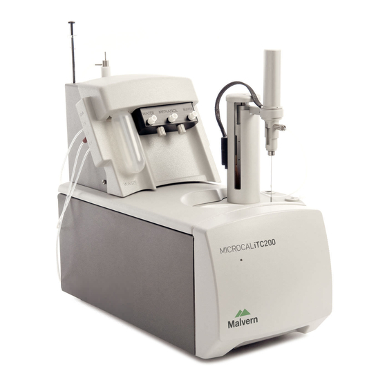
Introduction 1 Regulatory information 1.2 Regulatory compliance of connected equipment Any equipment connected to the MicroCal iTC should meet the safety requirements of EN 61010-1/IEC61010-1 or relevant harmonized standards. Within the European Union, connected equipment must be CE-marked. MicroCal iTC Operating Instructions 28-9639-77 AA... - Page 10 Introduction Instrument Instrument The MicroCal iTC (Isothermal Titration Calorimeter, 200 µL cell) unit directly measures heat evolved or absorbed in liquid samples as a result of mixing precise amounts of reactants. A spinning syringe is utilized for injecting and mixing of reactants. Spin rates are user selectable;...
- Page 11 Introduction 1 Instrument 1.3 Figure 1-2. MicroCal iTC complete system. Part Description Part Description Controller Washing module MicroCal iTC Tower Pipette Cell Unit Temperature differences between the reference cell and the sample cell are measured, calibrated to power units and displayed to the user as well as saved to disk. The data channel is referred to as the DP signal, or the differential power between the reference cell and the sample cell.
-
Page 12: Instrument
Introduction Instrument With the MicroCal iTC system the entire experiment takes place under computer control. The user inputs the experimental parameters (temperature, number of injections, injection volumes) and the computer carries out the experiment. <DoNotTranslate_GE_Color>Origin™ software is then used to analyze the ITC data using fitting models to calculate reaction stoichiometry (n), binding constant (K enthalpy (ΔH) and entropy (ΔS). - Page 13 Introduction 1 Control software 1.4 Control software In order for the system to initialize properly, all components must be powered up in the correct order. First, boot up the computer and log in to Windows. Once Windows has started, power the MicroCal iTC by operating the switch at the rear of the unit.
- Page 14 Introduction Control software Origin software Origin Real-Time Display This section describes the functionality of the optional copy of <DoNotTranslate_GE_Color>Origin for real-time display. When the software is opened, it will open the <DoNotTranslate_GE_Color>Origin™ project window VPITCPLOT.OPJ for real time data display. This project of <DoNotTranslate_GE_Color>Origin is dedicated to data display only, and should not be used for data analysis.
-
Page 15: Control Software 1.4
Introduction 1 Control software 1.4 time tools in <DoNotTranslate_GE_Color>Origin, refer to the MicroCal iTC Experimental and Data Analysis Tutorial Guide. MicroCal iTC Operating Instructions 28-9639-77 AA... - Page 16 Introduction Control software MicroCal iTC Operating Instructions 28-9639-77 AA...
-
Page 17: Safety Instructions
The points below are intended to enhance your safety awareness and to draw your attention to risks which only you, the operator, can prevent. While GE Healthcare works to ensure that the instrument is designed and tested to be as safe as possible, proper handling is also critical. - Page 18 Provide proper electrical power to the instrument. This should be 100 – 240 Volt, 50/60 Hertz alternating current, with a Ground Fault Circuit Interrupter (GFCI). Some power strips, such as the one provided by GE Healthcare with your instrument, contain a GFCI. All power plugs and cords should be 3-prong, grounded cables or outlets.
- Page 19 Safety instructions 2 Safety precautions 2.1 Using flammable liquids WARNING! A fume hood or similar ventilation system shall be installed when flammable or noxious substances are used. WARNING! Fire Hazard. Before starting the system make sure that there is no leakage.
- Page 20 Safety instructions Safety precautions Installing and moving the instrument WARNING! Power cord. Only use power cords delivered or approved by GE Healthcare. WARNING! Do not block the ventilation inlets or outlets on the system. WARNING! The Washing Module may only be powered by the power supply provided with the Unit.
- Page 21 WARNING! Repairs, alterations or modifications must only be carried out by a GE Healthcare specialist, or with explicit directions from a GE Healthcare technician. Removal or modification of any cover or component could result in an unsafe or easily damaged instrument.
- Page 22 Safety instructions Safety precautions WARNING! Disconnect power. Always disconnect power from the instrument before replacing any component on the instrument, unless stated otherwise in the user documentation. WARNING! Hazardous chemicals during run. When using hazardous chemicals, flush the entire system tubing with distilled water, before service and maintenance.
-
Page 23: Labels
Safety instructions 2 Labels 2.2 Labels Labels on the instrument The illustration below shows an example of the identification labels attached to the rear of the MicroCal iTC instrument. Figure 2-1. Back panel of instrument. Labels on the USB hub The illustration below shows an example of the label on the back of the USB hub. - Page 24 Safety instructions Labels Labels on the Washing Module The illustration below shows an example of the identification labels attached to the rear of the Washing Module. Figure 2-3. Labels on Washing Module. MicroCal iTC Operating Instructions 28-9639-77 AA...
- Page 25 Safety instructions 2 Labels 2.2 Symbols used in safety labels The system complies with the requirements for electromagnetic compliance (EMC) in Australia and New Zeeland. Warning! Read the user manual before using the system. Do not open any covers or replace parts unless specifically stated in the user manual.
- Page 26 Safety instructions Labels Controller • The controller shuts down, in an undefined state. • The MicroCal iTC run is interrupted immediately, in an undefined state. Washing module • The washing module shuts down immediately, in an undefined state. MicroCal iTC Operating Instructions 28-9639-77 AA...
-
Page 27: Recycling Procedures
Waste of electrical and electronic equipment must not be disposed as unsorted municipal waste and must be collected separately. Please contact an authorized representative of GE Healthcare for information concerning the decommissioning of equipment. MicroCal iTC Operating Instructions 28-9639-77 AA... - Page 28 Safety instructions Recycling procedures MicroCal iTC Operating Instructions 28-9639-77 AA...
-
Page 29: Installation
3 Installation NOTICE It is recommended that the installation of the MicroCal iTC instrument be performed by GE Healthcare personnel. This section provides information about the installation of MicroCal iTC Figure 3-1. MicroCal iTC with washing module and control computer.. - Page 30 It is recommended that you test a power conditioner, at your location, before you purchase it. If you believe you are experiencing power source related problems, please contact a GE Healthcare field engineer. Table 3-1. Power supply requirements.
-
Page 31: Transport
Check the equipment for damage before starting assembly and installation. Document any damage and contact your local GE Healthcare representative. Set up Arrange the components on the desktop similar to the picture of the system (see Figure 3-1). - Page 32 Installation Set up Remove the top and front panel. Remove the three screws and washers on the top of the instrument used to mount the injection tower. Figure 3-2. MicroCal iTC with washing module. Part Description Cell cleaning adaptor Washing module Solution tubes (Waste, Water, Methanol, Buffer) Cell port Fill port adaptor...
- Page 33 Installation 3 Set up 3.4 Attach the tower with the washers and screws. Do not seat the screws but leave them just slightly loose enough to slide the injector around for alignment in step 5. Carefully insert the pipette into the lock ring. Ensure that the pipette is fully seated and the black cable is parallel with the arm before tightening the screw (below).
- Page 34 Installation Set up Identify the only cable with the USB type B (mini) cable end. Connect the type B (mini) cable end to the USB hub (see Fig 3-4). Connect the USB type A end of that cable to the labeled Controller PC USB port. Figure 3-3.
- Page 35 Installation 3 Set up 3.4 Connect the green grounding strap wire between the Washing Module and the MicroCal iTC cell. Figure 3-5. Washing Module and MicroCal iTC cell. Note: 1 in Figure 3-5 is the power cord grommet. MicroCal iTC Operating Instructions 28-9639-77 AA...
- Page 36 Installation Set up Electrical connections MicroCal iTC cell Connect the power cord to the IEC 320 inlet power receptacle (see Figure 3-6 below) on the back of the cell. Connect the power plug only to a main power supply receptacle with a 3-wire protective Earth ground and a Ground Fault Circuit Interrupter (GFCI).
- Page 37 Installation 3 Set up 3.4 only to a main power supply receptacle with a 3-wire protective Earth ground and a Ground Fault Circuit Interrupter (GFCI). WARNING To enhance safety always plug the instrument into a Ground Fault Circuit Interrupter (GFCI) device. Figure 3-7.
- Page 38 Installation Set up Fluid connections Figure 3-8. Washing Module pipette wash station connections. Attach Washing Module Tubing • C1 to syringe fill port (Figure 3-8), • C2 to needle wash port (Figure 3-8), • C3 to top of cleaning device (Figure 3-9), •...
-
Page 39: Validation
Installation 3 Validation 3.5 Insert the vacuum vial and three solvent vials To install the vacuum vial (1 in Figure 3-10) slide the vial up and back, and screw it into its socket. To install a vial, insert the fill tubing and filter, if applicable, into the vial and slide it up and back into its slot. -
Page 40: Configuring A Microcal Itc
Installation Configuring a MicroCal iTC controller for networking Configuring a MicroCal iTC controller for networking On a MicroCal iTC controller, there are several actions that must be performed for the networking and MicroCal iTC control software to work properly. First, the InitDT watchdog program must be removed, and once the computer has been configured for the local domain, two folders must be given special permissions. -
Page 41: Operation
MicroCal iTC cell ready. Periods of inactivity GE Healthcare recommends that the MicroCal iTC application be closed and the master power be turned off, when the system will not be used for extended periods of time. -
Page 42: Loading The Cell
Operation Loading the cell lid fitting into the slot provided (see image below). Be careful not to leave any part of the tube in the path of the syringe needle to prevent damage. Figure 4-1. Micro centrifuge tube in the tube holder. Figure 4-2. - Page 43 Operation 4 Loading the cell 4.4 Pull approximately 300 µl of sample into the syringe, and tap the syringe glass so that all air is at the top volume of the syringe. Do not allow air to be put into the cells.
-
Page 44: Experimental Design
Operation Experimental design Be sure to insert the syringe in to the sample cell before starting the experiment. The instrument will seek experimental temperature, equilibrate to that temperature, start the titration syringe stirring, wait until the DP signal is steady, and then start performing injections. -
Page 45: Advanced Experimental Design
Operation 4 Advanced experimental design 4.6 When the software is first started, by default, the Experimental Design tab is selected; this contains the simple run controls. Experimental Mode can be Highest Quality, Minimum Protein, or High Speed. Highest Quality uses 20 injections. These parameters should produce data that is clear and easier to fit. -
Page 46: Instrument Controls
Operation Instrument controls Instrument controls Figure 4-5. Instrument control screenshow. The Instrument Controls tab contains the controls for direct operation of the instrument. At the top of the window, the user can Start the run, using whatever parameters are currently present in the Experimental Design or Advanced Experimental Design tabs. - Page 47 Operation 4 Instrument controls 4.7 The Pulse Control section allows for manually administering a DP calibration pulse. While this is not the most thorough method of checking the y-axis calibration, it is the quickest method. Pulses may be applied any time the DP signal is equilibrated and the resulting deflection used as a crude calibration assessment.
-
Page 48: Real Time Plot
Operation Real time plot will rinse the cell, this time with water, using greater quantities. This is especially useful after a detergent soak, to be sure of removing all of the detergent. Click the Detergent Soak and Rinse (Long) button and follow the prompts to load ~5% Contrad70. -
Page 49: Procedures After A Run
Operation 4 Procedures after a run 4.10 4.10 Procedures after a run The MicroCal iTC was designed to have its power on for extended periods of time. This will keep the system electronics at the normal operating temperature. It is recommended that the power of the MicroCal iTC cell be turned off during extended periods of down time, such as holidays and vacations. - Page 50 Operation 4.10 Procedures after a run MicroCal iTC Operating Instructions 28-9639-77 AA...
-
Page 51: Maintenance
Maintenance 5 Cell cleaning 5.1 5 Maintenance This section provides the user with information on the proper maintenance of the instrument to ensure proper function. Cell cleaning The MicroCal iTC uses fixed in place cells in order to provide maximum sensitivity and stability. -
Page 52: Inserting A New Syringe
Maintenance Inserting a new syringe Insert the syringe storage case into the loading hole. Figure 5-1. Syringe removal. Slide the pipette to the cleaning position and insert it firmly into the hole. Turn the inner metal syringe holder to the right several full rotations. This will unscrew the metal nut that holds the syringe in the pipette. -
Page 53: Syringe Cleaning
Maintenance 5 Syringe cleaning 5.4 Slide the case up until the syringe glass enters the bottom of the pipette. Figure 5-2. Syringe insertion. Let the case drop and gently push the syringe up through the filling hole and into the pipette. It will come to a stop with about 4 mm of syringe glass exposed below the metal. -
Page 54: Removing Pipette
Maintenance Removing pipette If this does not solve the issue, then as a backup method you can use the wire method explained here. Note this is not the preferred method and it is rare you will need to use this method. This must be done very carefully. -
Page 55: Changing Pipette Tips
Maintenance 5 Changing pipette tips 5.6 To reinsert the pipette, place the pipette in the socket on the arm and tighten the screw. Insert the cable into its slot, and tighten the two screws. It is a good idea to re-calibrate the open fill port position once the pipette has been replaced;... -
Page 56: Pipette Calibration
Maintenance Pipette calibration Pipette calibration The pipette may need to be re-calibrated, especially after a new pipette is installed. The “ITC => Pipette Tools” menu option will open the following popup. Figure 5-7. Pipette menu. The Initialize Pipette section will make the software run a routine that checks the sensors on the pipette and makes sure that the software knows certain constants of the pipette. - Page 57 The reported error in deflection or energy should be less than 1%. If the error is reported as higher than 1%, please contact GE Healthcare. For a more rigorous analysis, once the calibration is done and the system is thermostatting again, open the ITC Calibrations project.
-
Page 58: Replacement Of Fuses
If the fuses repeatedly blow, unplug the instrument and contact your local GE Healthcare representative. MicroCal iTC Operating Instructions 28-9639-77 AA... -
Page 59: Troubleshooting
The most extreme category is when a system is not working at all. Problems that prevent users from operating the instrument require immediate consultation with a GE Healthcare technician. Customers should not attempt to repair the hardware or software unless instructed to do so by a MicroCal service representative. - Page 60 Troubleshooting How to get help Carry out a minimum of 15, 2 µL injections of water into water. If, after completion of the steps listed above, the MicroCal iTC performance is not corrected, please contact the service department for help. The water runs should be provided to the MicroCal service technician for evaluation.
-
Page 61: Reference Information
Reference information 7 Instrument specifications 7.1 7 Reference information Instrument specifications Performance specifications Characteristic Data Operating Temperature Range 2°C to 80°C Response Time 10 seconds Cell Design: 200 µL, coin-shaped Titration Syringe: 40 µL Maximum Usable Volume: 35 µL Smallest Injection Size: 0.1 µL Stirring Rate 500 to 1500 r.p.m. -
Page 62: Ordering Information
Reference information Ordering information Electrical specifications for calorimeter Characteristic Data Voltage 100 to 240 Volts AC Frequency 50 / 60 Hz Power 70 Watts Fuses (2) 4.00 A, 250 V, Time Delay Output Secondary/Data connection only Protective Earth Terminals Internal/external marking Mode of Operation Continuous Classification... - Page 64 GE, imagination at work and GE monogram are trademarks of General Electric Company. www.gelifesciences.com/contact MicroCal is a trademark of GE Healthcare companies. Any use of this software is subject to GE Healthcare Standard Software End- GE Healthcare Bio-Sciences AB User License Agreement for Life Sciences Software Products. Björkgatan 30 All third party trademarks are the property of their respective owners.
Need help?
Do you have a question about the MicroCal iTC200 and is the answer not in the manual?
Questions and answers