Table of Contents
Advertisement
Quick Links
Advertisement
Table of Contents

Related Manuals for Pepperl+Fuchs WHA-GW


Summary of Contents for Pepperl+Fuchs WHA-GW
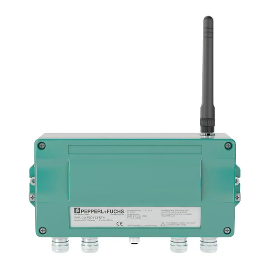
- Page 1 PROCESS AUTOMATION MANUAL WHA-GW-* ® WIRELESSHART GATEWAY...
- Page 2 WHA-GW-* With regard to the supply of products, the current issue of the following document is ap- plicable: The General Terms of Delivery for Products and Services of the Electrical In- dustry, published by the Central Association of the Electrical Industry (Zentralverband Elektrotechnik und Elektroindustrie (ZVEI) e.V.) in its most recent version as well as the...
-
Page 3: Table Of Contents
WHA-GW-* Safety....................6 Validity ............................6 Symbols used ........................6 Target Group/Staff .........................7 Reference to further documentation..................7 Declaration of Conformity.....................7 Marking ...........................7 Intended Use ..........................8 Mounting and Installation .....................8 Operation, Maintenance, Repair...................9 1.10 Delivery, Transport, Disposal....................9 Product Specifications ..............10 Introduction.......................... 10 Functional Overview...................... - Page 4 6.3.3 Set DTM address........................76 6.3.4 Set device address ........................77 6.3.5 List Editor..........................78 6.3.6 About .............................79 6.3.7 Change Password .........................79 6.3.8 Firmware Upgrade .........................80 Network Enhancement ......................81 Modbus Mapping .........................83 6.5.1 Overview..........................83 6.5.2 Modbus Mapping Description ....................84 Maintenance and repair..............87 WHA-GW* ..........................87...
- Page 5 WHA-GW-* Troubleshooting ................88 Faults indicated by Gateway LEDs ..................88 Wired Communication Faults .....................88 Wireless Communication Faults..................89 Technical specifications..............90 WHA-GW..........................90 Telecommunication Compliance..................92 Appendix A ..................93 10.1 Supported Commands ......................93 10.1.1 Universal Commands ......................93 10.1.2 Common Practice Commands ....................94 10.1.3 Wireless Commands......................94...
-
Page 6: Safety
WHA-GW-* Safety Safety Validity The chapter “Safety” is valid as instruction manual. Specific process and instructions in this document require special precautions to guarantee the safety of personnel. Symbols used This document contains information that you must read for your own personal safety and to avoid property damage. -
Page 7: Target Group/Staff
All products were developed and manufactured under observance of the applicable European standards and guidelines. Note! A Declaration of Conformity can be requested from the manufacturer. The product manufacturer, Pepperl+Fuchs GmbH, 68307 Mannheim, has a certified quality assurance system that conforms to ISO 9001. ISO9001 Marking ®... -
Page 8: Intended Use
WHA-GW-* Safety Intended Use The devices are only approved for appropriate and intended use. Ignoring these instructions will void any warranty and absolve the manufacturer from any liability. The approved usage of the connected device(s) and gateway can be taken from the corresponding parts of their instruction manual. -
Page 9: Operation, Maintenance, Repair
WHA-GW-* Safety The installation instructions in accordance with IEC/EN 60079-14 must be observed. Connection or disconnection of energized non-intrinsically-safe circuits is only permitted in the absence of a hazardous atmosphere. The device must be disconnected from the power supply prior to installation and maintenance. -
Page 10: Product Specifications
WHA-GW-* Product Specifications Product Specifications Introduction ® The HART communication protocol (Highway Addressable Remote Transducer) is used by many 4 ... 20 mA transmitters to enable digital communication for diagnosis and maintenance purposes. Many device parameters, but also measurement values, can be ®... -
Page 11: Functional Overview
WHA-GW-* Product Specifications The WirelessHART network is built up, organized and maintained by the WirelessHART Gateway and is therefore self-organizing and self-healing. The Gateway also takes care for connection to different host systems through different industrial protocol bus interfaces. The WirelessHART Gateway supplies the WirelessHART field devices with the necessary information for seamless network operation. -
Page 12: Network Management
WHA-GW-* Product Specifications 2.2.1 Network Management The WirelessHART Gateway contains a network manager. The network manager takes care of the wireless communication between the WirelessHART field devices. The network manager takes care of the creation and maintenance of the wireless mesh network to ensure proper communication between the WirelessHART field devices. -
Page 13: Security Management
WHA-GW-* Product Specifications In the next step, the network manager sends scheduling information to the field device. The field device is told how to participate in the network and receives various information from the WirelessHART Gateway: • Number and identity of neighboring WirelessHART field devices, •... - Page 14 WHA-GW-* Product Specifications Figure 2.3Network structure and corresponding I/O structure 1 HOST application 2 WirelessHART Gateway 3 WirelessHART field device (joined first): I/O card 0, channel 0 4 WirelessHART adapter (joined second): I/O card 1, channel 0 5 Wired devices 1...3 connected to WirelessHART adapter: I/O card 1, channel 1 If a WirelessHART device loses communication to the Gateway, it keeps its position in the Gateway's Instrument List and stays assigned to the respective I/O card.
-
Page 15: Gateway Cache Management
WHA-GW-* Product Specifications Long Tag Emulation The WirelessHART communication protocol uses the long tag to address devices. However, long tags are only supported by HART 6 devices and newer devices (HART 6 = version 6 of the HART communication protocol; current version: HART 7). Older devices, for example HART 5 devices, have to be addressed by the "Message"... -
Page 16: Scope Of Delivery
WHA-GW-* Product Specifications Scope of Delivery The scope of delivery of the WirelessHART Gateway includes: • Device WHA-GW-*, • Antenna W-ANT-2400-2DB-ROD, • 3 sealing plugs for unused cable glands, • Product documentation. Design The operating elements, connections and interfaces are accessible with open enclosure. - Page 17 WHA-GW-* Product Specifications Connections and Interfaces Figure 2.5Connections and Interfaces 1 Grounding terminal 2 RS-485 interfaces, duplicated terminal block for daisy-chain capability 3 Ethernet interface 4 Power supply connections (redundant) 5 Antenna 6 Antenna terminal 7 Cable glands...
-
Page 18: Installation
WHA-GW-* Installation Installation Mounting Considerations 3.1.1 Positioning the Gateway Install the Gateway first, before installing other WirelessHART devices. This way you can check for proper operation of new devices as they are installed. Nevertheless, consider the location of future WirelessHART devices that will be routed through the Gateway to ensure good connectivity. - Page 19 WHA-GW-* Installation The following diagrams show the antenna gain in two different planes. 0° 350° 10° 340° 20° 330° 30° 320° 40° 310° 50° 300° 60° 290° 70° 280° 80° 270° 90° 260° 100° 250° 240° 120° 230° 130° 220°...
-
Page 20: Examples For Good And Poor Positioning
WHA-GW-* Installation 3.1.3 Examples for Good and Poor Positioning Figure 3.3Wave propagation, schematic representation (alpha = approx. 45°, may vary considerably) 1 Weaker signal above and below; almost no signal directly above and below 2 Stronger signal sideways Figure 3.4Good positioning: Devices are within each others antenna range... - Page 21 WHA-GW-* Installation Figure 3.5Poor positioning: Devices are not within each others antenna range...
-
Page 22: Mounting The Gateway
WHA-GW-* Installation Mounting the Gateway Danger! Electrostatic discharge hazard The device contains non-conductive plastic parts. Care must be taken when operating the installed device because of possible electrostatic charges. Electrostatic charged surfaces may cause an ignition spark. Electrostatic charges must be avoided. For example, do not rub the device and never clean plastic surfaces with a dry cloth. -
Page 23: Connecting To Ethernet
WHA-GW-* Installation Figure 3.6Mounting holes and housing screws 1 Mounting holes for M6 screws 2 Housing screws Mounting the Gateway 1. Drill 2 holes into the mounting surface so that they match the holes of the housing. 2. Screw the device to the mounting surface using M6 screws. - Page 24 WHA-GW-* Installation Note! Tension relief and bending radii Ensure sufficient relief of tension on the cables during installation and note the minimum bending radii of the cables. Pin assignment of the Ethernet plug You do not need an Ethernet plug to connect the Ethernet cable to the Gateway. However, you need an Ethernet plug at the other end of the cable to connect the cable to an Ethernet hub, switch, router or PC.
- Page 25 WHA-GW-* Installation Crossover or straight through wiring There are different types of Ethernet cables, depending on the application. In a straight through cable, both cable ends have T568A plugs or both ends have T568B plugs. In a crossover cable, one end has a T568A plug and the other end a T568B plug.
- Page 26 WHA-GW-* Installation Connecting to Ethernet Network 1. Unscrew the 4 screws of the housing cover (see Figure 3.6 on page 23). 2. Remove the housing cover. 3. Route the Ethernet cable through the cable gland in the middle of the Gateway housing.
- Page 27 WHA-GW-* Installation Wiring with a T568A plug Gateway wiring with a T568A plug Gateway Terminal Crossover wiring Straight through wiring brown brown white/brown white/brown blue blue white/blue white/blue green orange white/green white/orange orange green white/orange white/green Cable shield Cable shield Table 3.2Wiring with a T568A plug...
-
Page 28: Connecting To Rs-485
WHA-GW-* Installation Connecting to RS-485 Danger! Explosion hazard in Zone 2 when operating powered Gateway If the Gateway is installed in Zone 2 and connected to power, there is an explosion hazard when operating DIP switches, buttons or connecting/disconnecting cables. - Page 29 The Gateway is now connected to the RS-485 network. The yellow RS-485 communication status LED starts flashing when a correct HART or Modbus protocol message is received (see chapter 6.1). Gateway wiring (RS-485 connection) Wire RS-485 cable Terminal WHA-GW Meaning RxD/TxD - (RS-485 A) RS-485 differential signal RxD/TxD + (RS-485 B)
-
Page 30: Connecting The Antenna
WHA-GW-* Installation Connecting the Antenna Danger! Loss of the device's certification Only use antennas that are specified in the data sheet. Danger! Explosion hazard in Zone 2 when operating powered Gateway If the Gateway is installed in Zone 2 and connected to power, there is an explosion hazard when operating DIP switches, buttons or connecting/disconnecting cables. -
Page 31: Connecting To Power Supply And Grounding
WHA-GW-* Installation Connecting to Power Supply and Grounding Danger! Explosion hazard in Zone 2 when operating powered Gateway If the Gateway is installed in Zone 2 and connected to power, there is an explosion hazard when operating DIP switches, buttons or connecting/disconnecting cables. - Page 32 WHA-GW-* Installation 7. If you want to connect a redundant power supply (optional), draw the second power cable through the cable gland on the far right of the housing. 8. Connect the second power cable to the second power supply connection "Line 2"...
-
Page 33: Commissioning
WHA-GW-* Commissioning Commissioning Important Steps to Getting Started There are different possibilities how to connect to the gateway and how to configure the gateway. The following overview tells you which steps to take. But first, please answer the following question. -
Page 34: Installing The Required Software
Where to download the required software? 1. Visit www.pepperl-fuchs.com and scroll down to the bottom of the page until you see the area Pepperl+Fuchs International site links. 2. Click on the Process Automation link. The Process Automation main page is loaded. -
Page 35: Updating The Dtm Catalog
WHA-GW-* Commissioning Installing the required Software ® 1. Install the Microsoft .NET Framework by starting the corresponding setup.exe file and following the installation instructions given on the screen. ® 2. Install PACTware by starting the corresponding setup.exe file and following the installation instructions given on the screen. -
Page 36: Connecting Via Rs485
WHA-GW-* Commissioning Connecting via RS485 Once the Gateway has been connected to the RS485 bus (see chapter 3.4), you may connect the RS485 bus to your PC. This can be done by using a RS485–RS232 converter or a RS485–USB converter. -
Page 37: Connecting Via Ethernet
WHA-GW-* Commissioning Connecting via Ethernet Once the gateway has been connected to the Ethernet (see chapter 3.3), you are ready to connect your PC. Connecting to the gateway via Ethernet 1. Connect the Ethernet cable to the Ethernet jack of your PC. -
Page 38: Creating A New Pactware Project
WHA-GW-* Commissioning Entering IP address and subnet mask 6. Choose Use the following IP address and type 192.168.1.100 into the field IP address. 7. Type 255.255.255.0 into the field Subnet mask. 8. Press OK. Your PC is now ready to communicate with the gateway. - Page 39 WHA-GW-* Commissioning Adding RS485 Communication DTM Note! The HART CommDTM is not included in the WirelessHART DTM Collection. It can be downloaded separately from www.pepperl-fuchs.com. For further information on downloading and installing the DTM, see chapter 4.2. 1. Select the entry HOST PC in the project view of your PACTware project.
- Page 40 WHA-GW-* Commissioning Parameter window of HART communication DTM 6. Set the parameters according to the following table. 7. Click OK to save the changes and to close the parameter window. Parameter Description Default Communication Set this parameter to HART multiplexer.
- Page 41 WHA-GW-* Commissioning Adding Ethernet Communication DTM 1. Select the entry HOST PC in the project view. 2. Choose Device > Add device or click the Add device icon on the toolbar. A device selection window opens (see on page 41).
- Page 42 WHA-GW-* Commissioning Parameter window of Ethernet communication DTM 6. Set the parameters according to your preferences. In most cases, the default values should be fine. 7. In some cases you might have to edit the Additional Functions > Set DTM addresses menu.
-
Page 43: Adding Device Dtm
1. In the project view, right-click on the entry of the communication DTM you have added in the previous step. 2. To add the device DTM, choose Add device. The Device for window opens (see on page 43). Device for window with Gateway DTM 3. Select the entry WHA-GW. - Page 44 WHA-GW-* Commissioning 4. Click OK. The Gateway DTM is added to the project (see on page 44). You may continue with parameterizing the Gateway as described in the following (see chapter 5). Gateway DTM in the PACTware project view 5. Remember to save your PACTware project from time to time (File > Save).
-
Page 45: Configuration
WHA-GW-* Configuration Configuration Configuration via DTM or Web Interface There are two possible ways of configuring the device: ® • Configuration via the device DTM within an FDT frame application, e.g. PACTware • Configuration via a browser-based web interface. The main difference is the concept of offline/online parameterization when configuring with DTM/FDT (see chapter 5.2). -
Page 46: Online And Offline Parameterization (Dtm)
WHA-GW-* Configuration 4. Type the IP address of the Gateway into the browser's address field. The factory default is 192.168 .1.1. If you have already changed the Gateway's IP address, type in the new IP address. NOTE: In some browsers, you might have to clear the address history first or add "/index.html"... - Page 47 WHA-GW-* Configuration Note! The data edited and stored in the device during online parameterization is not automatically synchronized with the offline data record in the PACTware project. If you only change device parameters online, the device data stored in the project differs from the data stored...
-
Page 48: Identification Parameters
WHA-GW-* Configuration Note! Many device parameters can be edited both online and offline. The parameters that can only be edited online are especially pointed out in the following sections. Identification Parameters The identification parameters provide various information about the device and identify the device within the network. -
Page 49: Wireless Communication Parameters
WHA-GW-* Configuration Wireless Communication Parameters 5.4.1 Setup The setup parameters contain the necessary information for establishing and maintaining a WirelessHART network. Figure 5.2Wireless Communication Parameters > Setup Note! Parameter Join Key The parameter Join Key can only be edited when the security mode is activated by means of a DIP switch inside the gateway housing. - Page 50 WHA-GW-* Configuration Caution! Possible loss of connection when changing Network ID If you change the Network ID parameter of an already operating WirelessHART network, be aware that the Gateway will store the new network ID. However, the new network ID will only be applied the next time the network is reformed (please note that reforming the network can take a long time).
-
Page 51: Instrument List
WHA-GW-* Configuration Parameter Description Default Write Join Stores the Network ID and Join Key to the Gateway. Information Please read the information related to the network ID and join key in this section including the security notes. Available only online. - Page 52 WHA-GW-* Configuration Behaviour of list items in the Instrument List • Whenever a wireless device joins the network, it will be automatically inserted into the Instrument List, if not already existing. Wired devices connected to a WirelessHART adapter will also be inserted.
- Page 53 WHA-GW-* Configuration Wireless Communication Parameters - Instrument List Parameter Description Default Max. Card Displays maximum number of cards in the I/O system. This – Number corresponds to the maximum number of wireless devices which can be connected to the Gateway.
-
Page 54: Burst Lists
WHA-GW-* Configuration Displayed information Description Status Wireless communication status of the device. : OK, device connected and identified. : No communication possible. : Communication possible, device not identified. Manufacturer Manufacturer of the selected device. Analogue Value Analogue value of the selected device's primary variable. - Page 55 WHA-GW-* Configuration • Publishing of at least one command will also ensure that the cached status information is updated for cached configuration commands. Figure 5.4Wireless Communication Parameters - Burst Lists Note! Online parameterization only The parameters listed in the following table are available only during online parameterization.
-
Page 56: Wired Communication Parameters
WHA-GW-* Configuration Network Explorer – Burst Messages NExplorer Contents Description Burst Command Displays the HART command number. Number of Number of burst messages the selected device has sent. packets Table 5.6Network Explorer – Burst Messages Wired Communication Parameters Note! If you are connected to the Gateway using the HART IP communication DTM (Ethernet), make sure to update the parameters of the HART IP communication DTM (see chapter 4.6.2) when changing the following Gateway parameters:... -
Page 57: Interfaces > Ethernet
WHA-GW-* Configuration Wired Communication Parameters - Serial Interface Parameter Description Default Termination Select if you prefer to activate the Gateway's DIP switches Resistor termination resistor via the DIP switches inside the Selection Gateway housing (see chapter 6.1) or under software control. - Page 58 Gateway If necessary, secify the IP address of the gateway in address the IP network (not the IP address of the WHA-GW). This parameter depends on the parameter IP configuration mode (DHCP, DNS). If you chose "Automatic", this parameter is read-only.
-
Page 59: Protocols > Hart
WHA-GW-* Configuration 5.5.3 Protocols > HART The protocol parameters configure the protocols that run over the serial interface or the Ethernet interface (HART or MODBUS). When using the serial interface, only one protocol can be active at a time (either HART or MODBUS), depending on the value of the serial interface parameter Protocol Selection (see chapter 5.5.1). -
Page 60: Protocols > Modbus
WHA-GW-* Configuration 5.5.4 Protocols > Modbus The protocol parameters configure the protocols that run over the serial interface or the Ethernet interface (HART or MODBUS). When using the serial interface, only one protocol can be active at a time (either HART or MODBUS), depending on the value of the serial interface parameter Protocol Selection (see chapter 5.5.1). - Page 61 WHA-GW-* Configuration Wired Communication Parameters - MODBUS protocol Parameter Description Default Bus Address Select if you prefer to specify the Gateway's polling DIP switches Selection address via the DIP switches inside the Gateway (serial) housing (see chapter 6.1) or under software control.
-
Page 62: Network Explorer Tables
WHA-GW-* Configuration Network Explorer Tables Certain information provided by the gateway DTM is displayed using the "Network Explorer". The Network Explorer is used within the following menu items: • Parameter > Wireless Communication > Instrument List (see chapter 5.4.2) •... - Page 63 WHA-GW-* Configuration In the Network Explorer tree structure on the left, all devices within the network are listed (see Figure 5.9 on page 62). The upper right part of the Network Explorer area contains general information about the device selected in the tree structure. The lower right part of the Network Explorer area contains more specific information about the selected device, depending on the context.
-
Page 64: Operation
WHA-GW-* Operation Operation Controls and Indicators Inside the gateway housing there are LED indicators, DIP switches and buttons. The controls and indicators are accessible with open enclosure. Danger! Explosion hazard in Zone 2 when operating powered Gateway If the Gateway is installed in Zone 2 and connected to power, there is an explosion hazard when operating DIP switches, buttons or connecting/disconnecting cables. -
Page 65: Leds
WHA-GW-* Operation 6.1.1 LEDs Figure 6.2LED indicators 1 RS-485 communication status (yellow LED) 2 Power supply (green LED) 3 WirelessHART communication status (yellow LED) 4 Fault (red LED) 5 Ethernet communication status (yellow LED) LED indicators LED indicators RS-485 communication status (yellow LED) -
Page 66: Buttons And Dip Switches
WHA-GW-* Operation LED indicators LED flashes A HART or MODBUS message is received by the gateway via the Ethernet interface. The LED does not flash if the message is not addressed to the gateway or if a communication error was detected within the message.. - Page 67 WHA-GW-* Operation Time pressed Function Function of button [A + B] (security mode enabled) > 3 seconds Network Manager reset: When pressed while the Security Mode is enabled (see Figure 6.4 on page 67), the buttons set the join key, network ID, radio power and access mode back to factory settings.
- Page 68 WHA-GW-* Operation DIP switches 1 ... 4 Polling address Note! When using the DIP switches 5 ... 6 for setting the baud rate, this baud rate applies for the HART protocol as well as the Modbus protocol. Alternatively you may set the baud rate using the configuration software (see chapter 5.5.3, see chapter 5.5.4).
-
Page 69: Diagnosis
WHA-GW-* Operation Diagnosis The Diagnosis function provides detailed information about the device, wireless/wired communication and health status. Note! Available only online The Diagnosis function is available only during online parameterization. Accessing the Diagnosis windows 1. In the PACTware project, right-click on the device. -
Page 70: Wireless Communication
WHA-GW-* Operation Parameter Description Message User defined message. Universal Revision of the device's universal commands. Only available command revision online. Device Revision Revision of the device specific commands. Only available online. Software Revision Software revision of the device. Only available online. -
Page 71: Wired Communication
WHA-GW-* Operation Note! Using the Network Explorer Please refer to the section "Network Explorer Tables" for information on using the Network Explorer (see chapter 5.6). Network Explorer – Details Contents Description Unique ID Unique device ID. Number of Number of neighboring WirelessHART devices in reach of the neighbors selected device. - Page 72 WHA-GW-* Operation Parameter Description Number of responses returned from the I/O system Table 6.4Diagnosis - Wired Communication - Overview Figure 6.8Diagnosis > Wired Communication > HART Note! Not all parameters from the Diagnosis > Wired Communication > HART window are used by the gateway.
- Page 73 WHA-GW-* Operation Parameter Description Ethernet Communication Non-recoverable hardware fault within the communication Fault controller associated with the Ethernet interface. Electronic Defect Non-recoverable hardware fault within the Gateway different from the other faults in the "Extended Device Malfunction" category. RS-485 Communication...
-
Page 74: Additional Dtm Functions
WHA-GW-* Operation Parameter Description Configuration Changed An operation was performed that changed the device's configuration. Device Malfunction The device detected a serious error or failure that compromises device operation. Cumulative Extended Device Status These bits are set to 1 whenever the related status applies to one or more devices (or sub-devices) connected to the gateway. -
Page 75: Reset
Press this button to restart the Gateway software application without any impact on the established network (which is not reformed). This function does not set the parameters of the WHA-GW back to their default values. It only restarts the Gateway software. -
Page 76: Set Dtm Address
WHA-GW-* Operation 6.3.3 Set DTM address The table in the Set DTM address window shows the WirelessHART devices configured in the PACTware project and their DTM addresses. The DTM address is the device long tag as specified in the device's DTM (offline data record). The DTM address is also displayed in the project tree structure of the PACTware project. -
Page 77: Set Device Address
WHA-GW-* Operation 6.3.4 Set device address The table in the Set device address window shows the WirelessHART devices in the network. The device address is the device long tag stored in the device. Note! Additional functions > Set device address is available only online (connection to the gateway and the WirelessHART device(s) active). -
Page 78: List Editor
WHA-GW-* Operation 6.3.5 List Editor Note! The function Additional Functions > List Editor is only available when using the Gateway DTM. It is not available in the web interface. Figure 6.12Additional Functions > List Editor The Instrument List backup table is a backup copy of the Instrument List (see chapter 5.4.2). -
Page 79: About
WHA-GW-* Operation The Instrument List backup is stored to your hard drive. 5. To import a file from your hard drive, press Import Table from File. 6. Choose an Instrument List backup file from your hard drive. The Instrument List backup file is imported. -
Page 80: Firmware Upgrade
WHA-GW-* Operation 6.3.8 Firmware Upgrade Note! The function Firmware Upgrade is available only in the Gateway's web interface and not in the DTM. Upgrading the Gateway's firmware 1. In the web interface (see chapter 5.1), choose Additional Functions > Firmware Up- grade. -
Page 81: Network Enhancement
WHA-GW-* Operation Firmware Upgrade: Installation completed Network Enhancement Once the WirelessHART network is running, there are some simple measures that will help enhancing network performance and reliability. Those measures are described in the following. Note! After having installed and set up a wireless network, give the network a couple of hours to stabilize itself before taking the following steps. -
Page 82: Expand The Network
WHA-GW-* Operation Figure 6.14Eliminating a bottleneck 1 Bottleneck 2 WirelessHART Gateway 3 Possible position of an additional WirelessHART device eliminating the bottleneck Expand the Network In an industrial environment, there are several potential obstacles for radio waves, for example buildings, walls, pipes, or even moving obstacles like trucks. Those obstacles can reflect, bend, diffuse or block radio waves. -
Page 83: Modbus Mapping
WHA-GW-* Operation If there are problems with other wireless technologies disrupting the WirelessHART network, you should configure the Gateway to skip certain channels known to provide persistent interference (Blacklisting). Blacklisting is a user configurable feature and is useful when other wireless networks are in the physical environment of the WirelessHART network (see chapter 5.4.1). -
Page 84: Modbus Mapping Description
CMD 84 with the sub-device index = 2 is mapped starting at register 30025, and so on. The information about the WHA-GW itself is mapped into registers 30001 to 30012. To find out the starting register of a certain sub-device, use the following formula: SIR = 30001 + 12*(SDI) "SIR"... - Page 85 WHA-GW-* Operation Sub-device Index Modbus Register Value Description Format (CMD 84) 30013 30014 Primary Variable 32-bit floating (loop current, mA unit) point 30015 30016 Primary Variable (device-specific unit) 30017 30018 Secondary Variable (device-specific unit) 30019 30020 Tertiary Variable (device-specific unit)
- Page 86 WHA-GW-* Operation Parameter Description 0x20 Cold start A power failure or device reset has occurred. 0x10 More status More status information is available via available Command 48 "Read additional status information". 0x08 Loop current fixed The loop current is being held at a fixed value and is not responding to process variations.
-
Page 87: Maintenance And Repair
WHA-GW-* Maintenance and repair Maintenance and repair WHA-GW* The national requirements apply to maintenance, servicing, and inspection of associated apparatus. No maintenance is necessary if the devices are operated properly, observing the mounting instructions and ambient conditions. The devices must not be repaired, changed or manipulated. If there is a defect, the product... -
Page 88: Troubleshooting
WHA-GW-* Troubleshooting Troubleshooting Faults indicated by Gateway LEDs Faults indicated by Gateway LEDs Indication Possible cause Corrective action Red LED is on Hardware fault which makes Try powering the Gateway down normal operation of the Gateway and up again. If the problem impossible. -
Page 89: Wireless Communication Faults
WHA-GW-* Troubleshooting Wireless Communication Faults Fault Possible cause Corrective action The Gateway The device has not yet joined the The joining process may take a cannot find a network. while. Check the join status in the WirelessHARTd Gateway's Instrument List. -
Page 90: Technical Specifications
WHA-GW-* Technical specifications Technical specifications WHA-GW Number of channels 2-channel Interface ® ® HART , HART UDP, MODBUS RTU, MODBUS TCP Wireless interface ® WirelessHART Supply Rated voltage 20 ... 30 V DC Power consumption < 5 W External bus... - Page 91 WHA-GW-* Technical specifications Controls 2 push buttons: - restore HART configuration - restore communication configuration Directive conformity Electromagnetic compatibility Directive 2004/108/EC EN 61326-1:2006 Radio and telecommunication terminal equipment Directive 99/5/EC ETSI EN 300 328: V1.7.1 (2006-10), ETSI EN 301 489-17: V1.2.1 (2002-08), EN 60950:2001...
-
Page 92: Telecommunication Compliance
WHA-GW-* Technical specifications Telecommunication Compliance • ETSI (R&TTE), • FCC Part 15.247 for wireless applications in the area of 2.4 GHz, • EN 300 328. The usage of 2400 MHz equipment is bound to local restrictions. Ensure that restrictions allow usage of this product before commissioning. -
Page 93: Appendix A
WHA-GW-* Appendix A Appendix A 10.1 Supported Commands The following tables show the HART commands supported by the device. Note! The Gateway – unlike a HART multiplexer – only accepts commands directly addressed to its HART slave address. 10.1.1 Universal Commands... -
Page 94: Common Practice Commands
WHA-GW-* Appendix A 10.1.2 Common Practice Commands Command Action Description Device Management Commands Perform device self test Initiates the self test function in the device Perform device reset Immediately after the response the microprocessor of the device will be reset. -
Page 95: Device Commands
WHA-GW-* Appendix A Command Action Description Read network tag Read the network tag. Read UTC time mapping Read the time setting for the network. Write Radio Power Read Radio Power Read Network Device's Statistics Active / White / Black lists commands... - Page 96 PROTECTING YOUR PROCESS Worldwide Headquarters Pepperl+Fuchs GmbH 68307 Mannheim · Germany Tel. +49 621 776-0 E-mail: info@de.pepperl-fuchs.com For the Pepperl+Fuchs representative closest to you check www.pepperl-fuchs.com/pfcontact www.pepperl-fuchs.com Subject to modifications 221981 / DOCT-1898C Copyright PEPPERL+FUCHS • Printed in Germany 07/2011...
Need help?
Do you have a question about the WHA-GW and is the answer not in the manual?
Questions and answers