Sign In
Upload
Manuals
Brands
Emerson Manuals
Transmitter
Micro Motion 2500
Emerson Micro Motion 2500 Manuals
Manuals and User Guides for Emerson Micro Motion 2500. We have
5
Emerson Micro Motion 2500 manuals available for free PDF download: Configuration And Use Manual, Installation Manual, Product Data Sheet
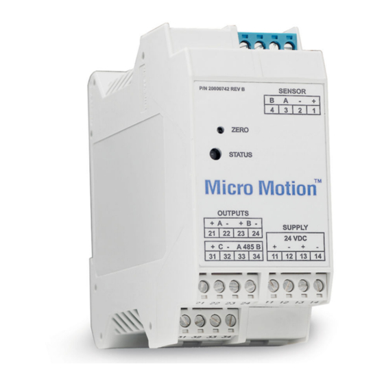
Emerson Micro Motion 2500 Configuration And Use Manual (282 pages)
Brand:
Emerson
| Category:
Transmitter
| Size: 8 MB
Table of Contents
Table of Contents
3
Chapter 1 Before You Begin
11
Overview
11
Safety
11
Determining Your Transmitter Type and Version
11
Transmitter Type, Installation Type, and Outputs Option Board
12
Version
13
Flowmeter Documentation
13
Using this Manual
13
Component Versions
14
Terminology
14
Communication Tools
15
Planning the Configuration
15
Pre-Configuration Worksheet
16
Micro Motion Customer Service
17
Chapter 2 Using the Transmitter Display
19
Overview
19
Components
19
Using the Optical Switches
20
Using the Display
20
Display Language
20
Viewing Process Variables
20
Display Menus
21
Display Password
21
Entering Floating-Point Values with the Display
22
Chapter 3 Connecting with Prolink II or Pocket Prolink Software
25
Overview
25
Requirements
25
Prolink II Configuration Upload/Download
26
Connecting from a PC to a Model 1700 or Model 2700 Transmitter
26
Connecting to the Service Port
27
Connecting to the RS-485 Terminals or an RS-485 Network
28
Connecting to the Primary Ma Output Terminals or to a HART Multidrop Network
30
Connecting from a PC to a Model 1500 or Model 2500 Transmitter
33
Connecting to the RS-485 Terminals or an RS-485 Network
33
Hart/Bell 202 Connections
36
Prolink II Language
37
Chapter 4 Connecting with the 275 HART Communicator or
39
Field Communicator
39
Overview
39
Communicator Models
39
Viewing the Device Descriptions
40
Using the 275 HART Communicator with the Model 2500
40
Connecting to a Transmitter
41
Connecting to Communication Terminals
41
Connecting to a Multidrop Network
43
Conventions Used in this Manual
43
HART Communicator Safety Messages and Notes
43
Chapter 5 Flowmeter Startup
45
Flowmeter Startup
45
Overview
45
Applying Power
46
Communication Methods after Power-Up
46
Performing a Loop Test
47
Trimming the Milliamp Outputs
48
Zeroing the Flowmeter
49
Preparing for Zero
49
Zero Procedure
50
Chapter 6 Required Transmitter Configuration
53
Overview
53
Characterizing the Flowmeter
54
When to Characterize
54
Characterization Parameters
54
How to Characterize
57
Configuring the Channels
57
Configuring the Measurement Units
57
Mass Flow Units
58
Volume Flow Units
59
Density Units
61
Temperature Units
61
Pressure Units
62
Configuring the Ma Output(S)
62
Configuring the Frequency Output(S)
62
Configuring the Discrete Output(S)
62
Configuring the Discrete Input
63
Establishing a Meter Verification Baseline
63
Chapter 7 Using the Transmitter
65
Overview
65
Special Applications
65
Recording Process Variables
66
Viewing Process Variables
66
With the Display
66
With Prolink II
66
With a Communicator
67
Viewing Transmitter Status and Alarms
67
Using the Status LED
67
Using the Display
67
Using Prolink II
69
Using the Communicator
69
Acknowledging Alarms
69
Using the Totalizers and Inventories
70
Viewing the Totalizers and Inventories
70
Controlling Totalizers and Inventories
71
Chapter 8 Optional Configuration
75
Overview
75
Configuration Map
75
How to Access a Parameter for Configuration
75
Configuring Standard Volume Flow Measurement for Gas
77
Using the Gas Wizard
77
Creating Special Measurement Units
78
About Special Measurement Units
78
Special Measurement Unit Procedure
79
Configuring the Petroleum Measurement Application (API Feature)
80
About the Petroleum Measurement Application
80
Configuring Cutoffs
82
Cutoffs and Volume Flow
83
Interaction with the AO Cutoffs
83
Configuring the Damping Values
83
Damping and Volume Measurement
84
Interaction with the Added Damping Parameter
84
Interaction with the Update Rate
84
Configuring the Update Rate
84
Effects of Special Mode
85
Configuring the Flow Direction Parameter
86
Configuring Events
89
Changing Event Setpoints from the Display
89
Configuring Slug Flow Limits and Duration
90
Configuring Fault Handling
91
Status Alarm Severity
91
Fault Timeout
95
Configuring the Display
95
Update Period
95
Language
95
Enabling and Disabling Display Functions
95
Changing the Scroll Rate
96
Changing the Display Password
96
Changing the Display Variables and Display Precision
96
Fixing Display Variable 1 to the Primary Ma Output
96
Configuring Digital Communications
97
Configuring Device Settings
97
Configuring Sensor Parameters
97
Configuring Write-Protect Mode
98
Chapter 9 Pressure Compensation, Temperature Compensation, and Polling
99
Overview
99
Pressure Compensation
99
Options
99
Pressure Correction Factors
100
Configuration
100
External Temperature Compensation
101
Configuring Polling
103
Chapter 10 Measurement Performance
107
Overview
107
Meter Verification, Meter Validation, and Calibration
107
Meter Verification
108
Meter Validation and Meter Factors
109
Calibration
109
Comparison and Recommendations
110
Performing Meter Verification
111
Preparing for the Meter Verification Test
111
Running the Meter Verification Test, Original Version
111
Running Smart Meter Verification
114
Reading and Interpreting Meter Verification Test Results
119
Setting up Automatic or Remote Execution of the Meter Verification Test
125
Performing Meter Validation
128
Performing Density Calibration
129
Preparing for Density Calibration
129
Density Calibration Procedures
130
Performing Temperature Calibration
133
Chapter 11 Custody Transfer
135
Overview
135
Locale-Specific Commissioning
135
Configuring the Weights and Measures Approval Agency
135
Special Restrictions When Using Custody Transfer Transmitters
136
Switching between Security Breach and Secure Mode
136
Security Breach Mode
136
Transmitter Outputs in Security Breach Mode
137
Configuring the Totalizers in Security Breach Mode
137
Secure Mode
137
Transmitter Outputs in Secure Mode
138
Operating the Totalizers in Secure Mode
138
Displaying Totalizer and Inventory Values
138
Chapter 12 Troubleshooting
139
Overview
139
Guide to Troubleshooting Topics
139
Micro Motion Customer Service
140
Transmitter Does Not Operate
140
Transmitter Does Not Communicate
140
Zero or Calibration Failure
141
Fault Conditions
141
HART Output Problems
141
I/O Problems
141
12.10 Simulation Mode
144
12.11 Transmitter Status LED
145
Model 1500/2500 Transmitters
145
Model 1700/2700 Transmitters with Displays
145
12.12 Status Alarms
146
12.13 Checking Process Variables
151
12.14 Diagnosing Wiring Problems
154
Checking the Power Supply Wiring
154
Checking the Sensor-To-Transmitter Wiring
155
Checking Grounding
155
Checking for RF Interference
155
Checking the HART Communication Loop
156
12.15 Checking the Communication Device
156
12.16 Checking the Output Wiring and Receiving Device
157
12.17 Checking Slug Flow
157
12.18 Checking Output Saturation
158
12.19 Setting the Loop Current Mode Parameter
158
12.20 Checking the Flow Measurement Unit
158
12.21 Checking the Upper and Lower Range Values
159
12.22 Checking the Frequency Output Scale and Method
159
12.23 Checking the Characterization
159
12.24 Checking the Calibration
159
12.25 Checking the Test Points
159
Obtaining the Test Points
160
Evaluating the Test Points
160
Excessive Drive Gain
161
Erratic Drive Gain
161
Low Pickoff Voltage
162
12.26 Checking the Core Processor
162
Checking the Core Processor LED
162
Core Processor Resistance Test (Standard Core Processor Only)
165
12.27 Checking Sensor Coils and RTD
167
9-Wire Remote or Remote Core Processor with Remote Transmitter Installation
167
4-Wire Remote or Integral Installation
168
Appendix A Default Values and Ranges
173
Overview
173
Most Frequently Used Defaults and Ranges
173
Appendix B Flowmeter Installation Types and Components
179
Overview
179
Model 1500/2500 Transmitters
179
Installation Diagrams
179
Component Diagrams
179
Wiring and Terminal Diagrams
179
Model 1700/2700 Transmitters
184
Installation Diagrams
184
Component Diagrams
184
Wiring and Terminal Diagrams
184
Appendix C Menu Flowcharts - Model 1500 an Transmitters
191
Overview
191
Model 1500 Output Board
191
Version Information
191
Prolink II Menus
192
C.4 Prolink II Menus
192
Communicator Menus
195
C.5 Communicator Menus
195
Appendix D Menu Flowcharts - Model 2500 CIO Transmitters
201
Overview
201
Version Information
201
Prolink II Menus
202
Communicator Menus
205
Appendix E Menu Flowcharts - Model 1700/2700 an Transmitters
211
Overview
211
Version Information
211
Prolink II Menus
212
Communicator Menus
215
Display Menus
221
E.5 Display Menus
221
Appendix F Menu Flowcharts - Model 1700/2700 IS Transmitters
229
Overview
229
Version Information
229
Prolink II Menus
230
Communicator Menus
233
Display Menus
239
F.5 Display Menus
239
Appendix G Menu Flowcharts - Model 2700 CIO Transmitters
247
Overview
247
Version Information
247
Prolink II Menus
248
G.3 Prolink II Menus
248
Communicator Menus
251
G.4 Communicator Menus
251
Display Menus
257
G.5 Display Menus
257
Appendix H Display Codes and Abbreviations
267
Appendix I NE53 History
269
Index
273
Advertisement
Emerson Micro Motion 2500 Configuration And Use Manual (238 pages)
Transmitters with Configurable Input/Outputs
Brand:
Emerson
| Category:
Transmitter
| Size: 4 MB
Table of Contents
Table of Contents
3
Part I Getting Started
9
Chapter 1 Before You Begin
11
About this Manual
11
Transmitter Model Code
11
Communications Tools and Protocols
11
Additional Documentation and Resources
12
Chapter 2 Quick Start
13
Power up the Transmitter
13
Check Meter Status
13
Transmitter Status Reported by LED
14
Make a Startup Connection to the Transmitter
14
Optional) Adjust Digital Communications Settings
15
Verify Mass Flow Measurement
15
Verify the Zero
15
Terminology Used with Zero Verification and Zero Calibration
16
Part II Configuration and Commissioning
19
Chapter 3 Introduction to Configuration and Commissioning
21
Configuration Flowchart
21
Default Values and Ranges
23
Disable Write-Protection on the Transmitter Configuration
23
Restore the Factory Configuration
23
Chapter 4 Configure Process Measurement
25
Configure Mass Flow Measurement
25
Configure Mass Flow Measurement Unit
25
Configure Flow Damping
27
Configure Mass Flow Cutoff
28
Configure Volume Flow Measurement for Liquid Applications
30
Configure Volume Flow Type for Liquid Applications
30
Configure Volume Flow Measurement Unit for Liquid Applications
31
Configure Volume Flow Cutoff
33
Configure GSV Flow Measurement
35
Configure Volume Flow Type for Gas Applications
35
Configure Standard Density of Gas
35
Configure Gas Standard Volume Flow Unit
37
Configure Gas Standard Volume Flow Cutoff
40
Configure Flow Direction
41
Options for Flow Direction
42
Configure Density Measurement
46
Configure Density Measurement Unit
46
Configure Two-Phase Flow Parameters
47
Configure Density Damping
49
Configure Density Cutoff
50
Configure Temperature Measurement
50
Configure Temperature Measurement Unit
50
Configure Temperature Damping
51
Effect of Temperature Damping on Process Measurement
52
Configure the Petroleum Measurement Application
52
Configure Petroleum Measurement Using Prolink III
52
Set up Temperature Data for Petroleum Measurement Using Prolink III
54
Configure Petroleum Measurement Using the Field Communicator
55
API Tables Supported by the Petroleum Measurement Application
57
Set up Concentration Measurement
58
Configure Concentration Measurement Using Prolink III
59
Configure Concentration Measurement Using the Field Communicator
61
Standard Matrices for the Concentration Measurement Application
63
Derived Variables and Calculated Process Variables
64
Configure Pressure Compensation
66
Configure Pressure Compensation Using Prolink III
66
Configure Pressure Compensation Using the Field Communicator
68
Options for Pressure Measurement Unit
69
Chapter 5 Configure Device Options and Preferences
71
Configure Response Time Parameters
71
Configure Update Rate
71
Configure Response Time
73
Configure Alert Handling
74
Configure Fault Timeout
74
Configure Status Alert Severity
75
Configure Informational Parameters
79
Configure Sensor Serial Number
79
Configure Sensor Material
79
Configure Sensor Liner Material
80
Configure Sensor Flange Type
80
Configure Descriptor
81
Configure Message
81
Configure Date
81
Chapter 6 Integrate the Meter with the Control System
83
Configure the Transmitter Channels
83
Configure the Ma Output
85
Configure Ma Output Process Variable
85
Configure Lower Range Value (LRV) and Upper Range Value (URV)
88
Configure AO Cutoff
89
Configure Added Damping
91
Configure Ma Output Fault Action and Ma Output Fault Level
92
Configure the Frequency Output
94
Configure Frequency Output Process Variable
94
Configure Frequency Output Polarity
95
Configure Frequency Output Scaling Method
96
Configure Frequency Output Mode
97
Configure Frequency Output Fault Action and Frequency Output Fault Level
98
Configure the Discrete Output
100
Configure Discrete Output Source
100
Configure Discrete Output Polarity
102
Configure Discrete Output Fault Action
104
Configure the Discrete Input
105
Configure Discrete Input Action
105
Configure Discrete Input Polarity
107
Configure Events
107
Configure a Basic Event
108
Configure an Enhanced Event
108
Configure Digital Communications
111
Configure Hart/Bell 202 Communications
111
Configure Modbus/Rs-485 Communications
117
Configure Digital Communications Fault Action
118
Chapter 7 Complete the Configuration
121
Test or Tune the System Using Sensor Simulation
121
Sensor Simulation
122
Back up Transmitter Configuration
123
Enable Write-Protection on the Transmitter Configuration
123
Chapter 8 Set up the Weights & Measures Application
125
Weights & Measures Application
125
Set up the Weights & Measures Application Using Prolink III
126
Part III Operations, Maintenance, and Troubleshooting
131
Chapter 9 Transmitter Operation
133
Record the Process Variables
133
View Process Variables
134
View Process Variables and Other Data Using Prolink III
134
View Process Variables Using the Field Communicator
134
View Transmitter Status Using the Status LED
134
View and Acknowledge Status Alerts
135
View and Acknowledge Alerts Using Prolink III
135
View Alerts Using the Field Communicator
136
Alert Data in Transmitter Memory
136
Read Totalizer and Inventory Values
137
Start and Stop Totalizers and Inventories
137
Reset Totalizers
138
Reset Inventories
138
Chapter 10 Operate the Transmitter with the Weights & Measures Application
141
Operate the Transmitter When the Weights & Measures Application Is Installed
141
Approved Methods to Read or Obtain Process Data
142
Effect of the Weights & Measures Application on Process Measurement and Outputs
142
Effect of the Weights & Measures Application on Operation and Maintenance Functions
143
Switch between Secured and Unsecured Mode
146
Switch between Secured and Unsecured Mode Using Prolink III
146
Switch between Secured and Unsecured Mode Using the Switching Utility
146
Clear Status Alarm A027: Security Breach
147
Replacing the Core Processor in a Weights & Measures Installation
147
Chapter 11 Measurement Support
149
Options for Measurement Support
149
Use Smart Meter Verification (SMV)
150
SMV Requirements
150
SMV Test Preparation
150
Run SMV
151
View Test Data
152
Schedule Automatic Execution of the SMV Test
155
Use PVR, TBR, and TMR
155
PVR, TBR, and TMR Applications
156
Piecewise Linearization (PWL) for Calibrating Gas Meters
157
Use the Fuel Consumption Application
157
Fuel Consumption Overview
157
Zero the Meter
157
Validate the Meter
158
Alternate Method for Calculating the Meter Factor for Volume Flow
160
Perform a (Standard) D1 and D2 Density Calibration
161
Perform a D1 and D2 Density Calibration Using Prolink III
161
Perform a D1 and D2 Density Calibration Using the Field Communicator
162
Perform a D3 and D4 Density Calibration (T-Series Sensors Only)
163
Perform a D3 or D3 and D4 Density Calibration Using Prolink III
164
Perform a D3 or D3 and D4 Density Calibration Using the Field Communicator
165
Perform Temperature Calibration
166
Perform Temperature Calibration Using Prolink III
167
Perform Temperature Calibration Using the Field Communicator
168
Chapter 12 Troubleshooting
169
Status LED States
170
Status Alerts, Causes, and Recommendations
170
Flow Measurement Problems
178
Density Measurement Problems
180
Temperature Measurement Problems
181
Milliamp Output Problems
182
Frequency Output Problems
184
Discrete Output Problems
184
Discrete Input Problems
185
Using Sensor Simulation for Troubleshooting
185
Check Power Supply Wiring
186
Check Sensor-To-Transmitter Wiring
186
Check Grounding
187
Perform Loop Tests
187
Perform Loop Tests Using Prolink III
188
Perform Loop Tests Using the Field Communicator
189
Trim Ma Output
191
Trim Ma Output Using Prolink III
191
Trim Ma Outputs Using the Field Communicator
191
Check the HART Communication Loop
192
Check HART Address and Ma Output Action
193
Check HART Burst Mode
193
Check Lower Range Value and Upper Range Value
193
Check Ma Output Fault Action
194
Check for Radio Frequency Interference (RFI)
194
Check Frequency Output Mode
194
Check Frequency Output Scaling Method
195
Check Frequency Output Fault Action
195
Check Flow Direction
195
Check the Cutoffs
196
Check for Two-Phase Flow (Slug Flow)
196
Check the Drive Gain
196
Collect Drive Gain Data
198
Check the Pickoff Voltage
198
Collect Pickoff Voltage Data
199
Check for Internal Electrical Problems
199
Check the Sensor Coils
200
Check the Core Processor LED
202
Core Processor LED States
202
Perform a 700 Core Processor Resistance Test
204
Appendix A Using Prolink III with the Transmitter
205
Basic Information about Prolink III
205
Connect with Prolink III
206
Connection Types Supported by Prolink III
206
Connect with Prolink III to the Service Port
207
Make a Hart/Bell 202 Connection
209
Connect with Prolink III to the RS-485 Port
213
Appendix B Using a Field Communicator with the Transmitter
217
Basic Information about the Field Communicator
217
Connect with the Field Communicator
218
Appendix C Default Values and Ranges
221
Default Values and Ranges
221
Appendix D Transmitter Components and Installation Wiring
227
Installation Types
227
Power Supply Terminals
229
Input/Output (I/O) Wiring Terminals
230
Appendix E NE 53 History
231
NE 53 History
231
Emerson Micro Motion 2500 Installation Manual (92 pages)
MVD Transmitters
Brand:
Emerson
| Category:
Transmitter
| Size: 16 MB
Table of Contents
Table of Contents
3
October 2018 MMI
6
Chapter 1 Planning the Installation
7
About this Document
7
Installation Architecture
7
Hazardous Area Installations
8
Chapter 2 Transmitter Output Installation
9
Transmitter Output Installation: Analog Outputs for Model 1700/2700 Transmitters
10
Transmitter Output Installation Model 2750 Transmitter with Configurable Inputs and Outputs
11
Transmitter Output Installation: Model 2700 with Configurable Inputs and Outputs
12
Transmitter Output Installation: Profibus-PA Outputs for Model 1700/2700 Transmitters
13
Transmitter Output Installation Model 1700/2700 with Intrinsically Safe Installation
14
Transmitter Output Installation Model 1700/2700 with Fieldbus
15
Chapter 3 Model 1700/2700 4-Wire Installation
17
Model 1700/2700 4-Wire Installation: Remote Transmitter to Enhanced Core Processor Mounted on Sensor
18
Model 1700/2700 Transmitter 4-Wire Installation - Remote Transmitter to Core Processor Mounted on Sensor
19
Model 1700-2700 Transmitter 4-Wire Remote Transmitter Installation to Core Processor Mounted on CMF400 Sensor with Booster Amplifier
20
Model 1700/2700 Transmitter 4-Wire Remote Transmitter to Core Processor Mounted on D600 Sensor
21
Chapter 4 Direct Host 4-Wire Installation
23
Direct Host 4-Wire Installation - Core Processor to Direct Host through a Safety Barrier
24
Direct Host 4-Wire Installation of Enhanced Core Processor to a Direct Host through a Safety Barrier
25
Chapter 5 Model 800 Enhanced Core Processor
27
Chapter 6 Model 2750 4-Wire Installation
29
Chapter 7 Model 1500/2500 4-Wire Installation
31
Remote Transmitter to Enhanced Core Processor Mounted on Sensor
32
Remote Transmitter to Core Processor Mounted on CMF, F, H, R, CNG, and T Sensor
33
Remote Transmitter to Core Processor Mounted on CMF400 Sensor with Booster Amplifier
34
Remote Transmitter to Core Processor Mounted on D600 Sensor
35
Chapter 8 Model 3700 Transmitter 4-Wire Installation
37
Model 3700 Transmitter to Enhanced Core Processor Mouted on Sensor
38
Model 3700 Transmitter to Core Processor Mounted on CMF, F, H, R, CNF, and T Sensors
39
Remote Model 3700 Transmitter to Core Processor Mounted on CMF400 Sensor with Booster Amplifier
40
Model 3700 Remote Transmitter to Core Processor Mounted on D600 Sensor
41
Chapter 9 Model 3500 Transmitter 4-Wire Installation
43
Remote Model 3500 Transmitter to Enhanced Core Processor Mounted on Sensor
44
Remote Model 3500 Transmitter to Core Processor Mounted on CMF, F, H, R, CNG and T Sensors
45
Remote Model 3500 Transmitter to Core Processor Mounted on CMF400 Sensor with Booster Amplifier
46
Remote Model 3500 Transmitter to Core Processor Mounted on D600 Sensor
47
MMI-20001965 October
27
Chapter 10 Model LFT 4-Wire Installation to LF Sensor
49
Profibus-PA Transmitter Remotely Mounted to LF Sensor
50
Ma/Fo Transmitter Remotely Mounted to LF Sensor
51
FOUNDATION Fieldbus ™ Transmitter Remotely Mounted to LF Sensor
52
Config I/O Transmitter Remotely Mounted to LF Sensor
53
DIN Rail Transmitter Remotely Mounted to LF Sensor
54
Chapter 11 Model 1700/2700 Transmitter 9-Wire Integral Installations
55
Model 1700/2700 Transmitter with Integrally-Mounted Processor to Junction Box on CMF, F, H, T, D, and DL Sensors
56
Model 1700/2700 Transmitter with Integrally-Mounted Core Processor to 9-Wire Junction Box on CMF400 Sensor with Booster Amplifier
57
Model 1700/2700 Transmitter with Integrally-Mounted Core Processor to Junction Box on D600 Sensor
58
Model 1700/2700 Transmitter with Integrally-Mounted Core Processor to 9-Wire Junction Box on DT Sensor
59
Chapter 12 Model 1700/2700 9-Wire Remote Installations
61
Model 1700/2700 Transmitter Installation to Remote Core Processor to 9-Wire Junction Box on CMF, F, T, D, and DL Sensors
62
Model 1700/2700 Transmitter to Remote Mount Core Processor to 9-Wire Junction Box on CMF400 Sensor with Booster Amplifier
63
Model 1700/2700 Transmitter to Remote Core Processor to 9-Wire Junction Box on D600 Sensor
64
Model 1700/2700 Transmitter to Remote Core Processor to 9-Wire Junction Box on DT Sensor
65
Chapter 13 Model 1500/2500 9-Wire Installation
67
Model 1500/2500 Transmitter to Remote Mount Core Processor to 9-Wire Junction Box on CMF, D (Except D600), DL, F, H, and T Sensors
68
Model 1500/2500 Transmitter to Remote Core Processor to 9-Wire Junction Box on CMF400 Sensor with Booster Amplifier
69
Model 1500/2500 Transmitter to Core Processor to 9-Wire Junction Box on D600 Sensor
70
Model 1500/2500 Transmitter to Core Processor to 9-Wire Junction Box on DT Sensor
71
Chapter 14 Model 3700 9-Wire Installation Instructions
73
Model 3700 Transmitter to Remote Mount Core Processor to 9-Wire Junction Box on CMF, D (Except D600), DL, F, H, and T Sensors
74
Model 3700 Transmitter to Remote Core Processor to 9-Wire Junction Box on CMF400 Sensor with Booster Amplifier
75
Model 3700 Transmitter to Remote Core Processor to 9-Wire Junction Box on D600
76
Model 3700 Transmitter to Remote Mount Core Processor to 9-Wire Junction Box on DT Sensor
77
Chapter 15 Model 3500 9-Wire Installation
79
Model 3500 Transmitter to Remote Core Processor to 9-Wire Junction Box on CMF, D (Except D600), DL, H, and T Sensors
80
Model 3500 Transmitter to Remote Core Processor to 9-Wire Junction Box on CMF400 Sensor with Boost Amplifier
81
Model 3500 Transmitter to Remote Mount Core Processor to 9-Wire Junction Box on D600 Sensor
82
Model 3500 Transmitter to Remote Mount Core Processor to 9-Wire Junction Box on DT Sensor
83
Chapter 16 D600 Remote Booster Amplifier Installation
85
D600 Remote Booster Amplifier Installation with Core Processor Remotely Mounted from Sensor and Transmitter
86
D600 Remote Booster Amplifier with Junction Box Remotely Mounted from Sensor and Transmitter
87
Appendix A List of Drawings
89
Advertisement
Emerson Micro Motion 2500 Installation Manual (60 pages)
Brand:
Emerson
| Category:
Transmitter
| Size: 4 MB
Table of Contents
Table of Contents
3
Chapter 1 Planning
5
Meter Components
5
Installation Types
5
Maximum Cable Lengths between Sensor and Transmitter
7
Output Options
8
Environmental Limits
9
Hazardous Area Classifications
9
Power Requirements
9
Chapter 2 Mounting and Sensor Wiring for 4-Wire Remote Installations
11
Mounting the Transmitter to a DIN Rail
11
Prepare the 4-Wire Cable
12
Wire the Transmitter to the Sensor
15
Ground the Flowmeter Components
16
Chapter 3 Mounting and Sensor Wiring for Remote Core Processor with Remote Sensor Installations
17
Mounting the Transmitter to a DIN Rail
17
Mount the Remote Core Processor
18
Prepare the 4-Wire Cable
19
Wire the Transmitter to the Remote Core Processor
22
Prepare the 9-Wire Cable
23
Wire the Remote Core Processor to the Sensor Using Jacketed Cable
29
Wire the Remote Core Processor to the Sensor Using Shielded or Armored Cable
32
Ground the Meter Components
36
Chapter 4 Wiring the Power Supply
38
Wire the Power Supply
38
Chapter 5 I/O Wiring for Model 1500 Transmitters
39
Basic Analog Wiring
39
Hart/Analog Single Loop Wiring
39
HART Multidrop Wiring
40
Internally Powered Frequency Output Wiring
41
Chapter 6 I/O Wiring for Model 2500 Transmitters
42
Ma/Hart Wiring
42
Frequency Output Wiring
44
Discrete Output Wiring
47
Discrete Input Wiring
50
Chapter 7 Specifications
51
Electrical Connections
51
Input/Output Signals
52
Environmental Limits
55
Physical Specifications
56
Index
59
Emerson Micro Motion 2500 Product Data Sheet (28 pages)
Micro Motion 3000 Series Transmitters and Discrete Controllers
Brand:
Emerson
| Category:
Transmitter
| Size: 0 MB
Table of Contents
Table of Contents
3
Housings
4
Applications
4
Interface/Display
5
Electrical Connections
5
Input Signals
6
Output Signals
6
Environmental Specifications
8
Power Supply
8
Hazardous Area Classifications
9
Model 3100 Accessory
10
Model 3500/3700 Liquid Flow Performance
10
Model 3500/3700 Density Performance (Liquid Only)
11
Model 3500/3700 Gas Flow Performance
11
Weight
11
Dimensions
12
Ordering Information
16
Advertisement
Related Products
Emerson Micro Motion Transmitters and Discrete Controllers Series 3000
Emerson Micro Motion
Emerson Micro Motion ELITE
Emerson Micro Motion 3300
Emerson Micro Motion 2000 Series
Emerson Micro Motion 4200
Emerson Micro-Motion 2400S
Emerson MicroMotion FOUNDATION 5700
Emerson MAS 2600
Emerson Magtech MLT-350FF Series
Emerson Categories
Controller
Control Unit
Transmitter
Measuring Instruments
Fan
More Emerson Manuals
Login
Sign In
OR
Sign in with Facebook
Sign in with Google
Upload manual
Upload from disk
Upload from URL