
Related Manuals for X-Rite 890


Summary of Contents for X-Rite 890
- Page 1 A U T O M A T I C S T R I P R E A D I N G D E N S I T O M E T E R Operation Manual...
- Page 3 X-Rite 890 Auto Strip Reading, Color Photographic Densitometer. This instrument represents the very latest in microcontrollers, integrated circuits, optics, and display technology. As a result, your X-Rite instrument is a rugged and reliable instrument whose performance and design exhibit the qualities of a finely engineered instrument, which is not surpassed.
- Page 4 VORSICHT: Betriebsgefahr besteht bei Gebrauch von anderen Adaptern als X-Rite SE30-77 (100-240 V). AVISO: No use otro adaptador C.A. que no sea la pieza X-Rite SE30-77 (100- 240V), por el riesgo de mal funcionamiento del equipo. ATTENTION: Ne pas utiliser d’adaptateur autre que SE30-77 (100-240V) de X- Rite au risque de mauvais fonctionnement de l’appareil.
- Page 5 Model No.: Directive(s) Conformance: EMC 89/336/EEC LVD 73/23/EEC WEEE As of August 13, 2005, X-Rite products meet the European Union – Waste Electrical and Electronic Equipment (WEEE) directive. Please refer to www.xrite.com for more information on X-Rite’s compliance with the WEEE directive.
- Page 6 (excluding battery pack) for a period of 12 months. This warranty shall be fulfilled by the repair or replacement, at the option of X-Rite, of any part or parts, free of charge including labor, F.O.B. its factory or authorized service center.
-
Page 7: Table Of Contents
TABLE OF CONTENTS This manual is organized into eight sections and four appendices. In order to make the best use of your instrument, it is recommended that you read all sections and appendices. SECTION ONE - Getting Started Unpacking and Inspection __________________________________ 1-1 Packing Drawing and Parts List _______________________ 1-1 Product Description_______________________________________ 1-2 Applying Power _________________________________________ 1-3... - Page 8 Replacing the Read Lamp __________________________________ 5-4 Troubleshooting Tips _____________________________________ 5-5 APPENDIX A - Technical Specification APPENDIX B - Display Messages APPENDIX C - Term Abbreviations APPENDIX D - Parts List and Packaging Drawing APPENDIX E - 890 Instrument Firmware Update...
-
Page 9: Unpacking And Inspection
If reshipment is necessary, the instrument should be packaged in the original carton. If the original carton is not available, contact X-Rite to have a replacement shipped to you. Packaging Drawing and Parts List Check your packaging contents against your packing list and your original order. -
Page 10: Product Description
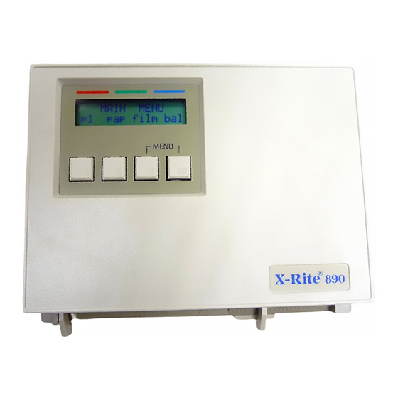
S E C T I O N O N E PRODUCT DESCRIPTION The X-Rite 890 automated instruments measures paper, film, and printer balance control strips. Simply insert the strip into the instrument for motorized, automatic measurements. Red, green, and blue density data is sorted for fields such as HD, LD, and Stain, then simultaneously displayed and transmitted to a minilab printer for analysis. -
Page 11: Applying Power
To apply power to the instrument: 1. Verify that the voltage indicated on the adapter complies with the AC line voltage in your area. If not, contact X-Rite or your authorized representative. 2. Insert the small plug from the adapter into the power-input connector on the instrument. -
Page 12: User Interface
S E C T I O N O N E USER INTERFACE The 890 instrument incorporates a three page menu system. Menu pages are displayed by continually pressing keyswitch l (p#) on the instrument. The first page contains all the predefined control strips. The last two pages provide access to the instrument setup options and strip measurement data. -
Page 13: Display And Keyswitch Definition
G E T T I N G S T A R T E D Display and Keyswitch Definition The characters in the bottom row of the display dictate which function is selected or which action takes place when a corresponding keyswitch is pressed. -
Page 14: Adjusting The Paper Guides
S E C T I O N O N E ADJUSTING THE PAPER GUIDES To accommodate various size paper strips, the instrument has an adjustable paper guide on each side of the strip entrance. Each paper guide has a pointer (triangle) that is aligned with a number on the guide rail. -
Page 15: Strip Measurement Techniques
G E T T I N G S T A R T E D STRIP MEASUREMENT TECHNIQUES All control strip types should have at least a 30.5mm (1.25”) leader before the first measurable patch. However, strips with less than a 30.5mm leader can also be measured reliably if required. - Page 16 S E C T I O N O N E Single Pass Single pass strips require the strip to be inserted into the instrument once. In this example, the strip—Kodak RA4—can be inserted in either direction. Refer to your Control Strip and Balance Print Format Guide for information on all strips supported.
- Page 17 G E T T I N G S T A R T E D Indicates magenta patches are PASS TWO Guide number flashes, indicting strip positioning Indicates yellow patches are measured PASS THREE Guide number flashes, indicting strip positioning The third pass requires the strip to be rotated to take the measurement.
-
Page 18: Film Strip
S E C T I O N O N E Film Strip The Film category requires that the film strip be inserted into the 35mm slot located above the center diamond. In this example—Kodak C41—the strip can be inserted in either direction. Refer to your Control Strip and Balance Print Format Guide for information on all strips supported. -
Page 19: Calibration Information
If your Auto-Cal strip gets ruined or worn, you can order a replacement from X-Rite or your local dealer. Order Part Number 880-100. Frequency of Calibration Under normal operating conditions, the instrument should be calibrated... -
Page 20: Auto Calibration Procedure
2. Insert the designated end of the Auto-Cal strip into the 35mm slot until it comes to rest against the drive rollers. X-RITE Auto-Cal Strip P/N 880-100 Patent Pending SERIAL #: XXX-XXX 35mm slot CAL R= 0.04 G= 0.07 B= 0.08... -
Page 21: Manual Calibration Procedure
2. Using the same densitometer, measure the white area below the first black bar on the X-Rite Auto-Cal strip and record the Red, Green, and Blue values. X-RITE Auto-Cal Strip P/N 880-100 Patent Pending SERIAL #: XXX-XXX CAL R= 0.04 G= 0.07 B= 0.08... - Page 22 Auto-Cal strip into the 35mm slot until it comes to rest against the drive rollers. INSERT CAL STRIP auto MANUAL X-RITE Auto-Cal Strip P/N 880-100 Patent Pending SERIAL #: XXX-XXX 35mm slot CAL R= 0.04 G= 0.07 B= 0.08 INSERT THIS END Note insertion direction •...
-
Page 23: Instrument Configuration
S E C T I O N T H R E E Setting System Configuration The system configuration allows you to customize your instrument to meet your requirements. The configuration should be viewed and edited as needed before any measurements are taken. Section Three Contents •... -
Page 24: Configuration Options
S E C T I O N T H R E E Page 2 Configuration Options IO preset This options provides several QC system selections. All the necessary RS-232 interface parameters are automatically set when a predefined I/O preset is selected. A “CUSTOM” preset is available which allows you manually set all available I/O options. -
Page 25: Configuration Options
S E T T I N G S Y S T E M C O N F I G U R A T I O N When set to On (XON), this enables bi-directional transmit On/Off protocol. When set to Off (xon), the instrument ignores XON/OFF codes. Note, usage is limited to output at this point. - Page 26 S E C T I O N T H R E E • You can save and exit the configuration at anytime without editing all options. This is accomplished by simultaneously pressing key l and key ll when SAVE is displayed in the screen. •...
- Page 27 S E T T I N G S Y S T E M C O N F I G U R A T I O N 4. Page 2a Configuration Screen • Press key ll (RCI) to page through and select a remote control interface option (OFF, ON, TTL).
- Page 28 S E C T I O N T H R E E 7. Page 2d Configuration Screen • Press key ll (baud) to page through and select a baud rate option (300, 600, 1200, 2400, 4800, 9600, 19200, 38400, 57600). •...
-
Page 29: Measuring Strips
S E C T I O N F O U R Strip Operation It is important to make sure control strips and reference strips used are from the same batch number. Always inspect control strips for damage before measuring. Care must also be taken when handing strips. - Page 30 S E C T I O N F O U R 3. Measure strip • For paper strips, adjust the paper guides according to the number displayed on the screen. If multiple pass, note what color is to be measured first. Insert strip until it comes to rest against the drive rollers. •...
-
Page 31: View Strip Data
S T R I P O P E R A T I O N View Strip Data Control strip data consists of the “actual” values measured by the instrument. Control strip data is viewed after a strip measurement or by selection from the Main Menu (p2). -
Page 32: Manually Transmitting Strip Data
S E C T I O N F O U R MANUALLY TRANSMITTING STRIP DATA The manual transmit function allows you to transmit data for the last measurement taken in the paper, film, and printer balance categories. 1. Press key lll (xmit) located on Main Menu page (p2) to enter Xmit Menu screen. -
Page 33: Repair Information
Troubleshooting Tips REPAIR INFORMATION The X-Rite 890 is covered by a one-year limited warranty and should be referred to the factory or an authorized service center for repairs within the warranty period. Attempts to make repairs within this time frame may void the warranty. -
Page 34: Cleaning The Instrument
S E C T I O N F I V E CLEANING THE INSTRUMENT Your instrument requires very little maintenance to achieve years of reliable operation. However, to protect your investment and maintain reading accuracy, a few simple cleaning procedures should be performed from time to time. -
Page 35: Cleaning The Calibration Strip
S E R V I C E A N D G E N E R A L M A I N T E N A N C E Cleaning the Calibration Strip (Part Number 880-100) The Auto-Cal strip can be cleaned with a mild soap detergent, and wiped dry with a clean, lint-free cloth. -
Page 36: Replacing The Read Lamp
S E C T I O N F I V E REPLACING THE READ LAMP (PART NUMBER 880-07) NOTICE: New lamp may appear bent, DO NOT attempt to straighten. 1. Remove four screws (2) securing the bottom cover (3) with a phillips- head screwdriver. -
Page 37: Troubleshooting Tips
• Recalibrate instrument. • Clean reflection cal strip or replace if bad. • Replace read lamp.* • Contact X-Rite or Authorized Service Center. Transmission measurement incorrect: • Recalibrate instrument. • Replace read lamp.* • Contact X-Rite or Authorized Service Center. - Page 38 S E C T I O N F I V E...
- Page 39 A P P E N D I X A Technical Specifications Transmission Process Control Film Width 35mm fixed slot or 1.4–6.0in. adjustable Measurement Speed 1.1 to 1.4 in./sec. (1.2 in./sec. typical) Spectral Response Status M Density Range 0–4.0D Density Accuracy ±.02D (0–3.0D), ±1% (3.1–3.4D) ±3% (3.5–4.0D) Density Repeatability...
- Page 40 A P P E N D I X A...
- Page 41 If any error messages listed, or not listed should appear, make a note of it and take the appropriate steps to try to correct it. If an error message is consistently displayed, contact X-Rite or an authorized service center.
- Page 42 A P P E N D I X B Message Reason Possible Cause Solution UNRECOGNIZABLE Unit did not feed Strip inserted in Insert strip correctly, Sec. 1. AUTO-CAL STRIP! consistently. backwards or upside- (during reflection cal) down. Cal strip is dirty. Clean cal strip, Sec.
- Page 43 A P P E N D I X C Term Abbreviations Automatic Line Feed Strip is one pass and may be read in either direction (strip measurement mode) AXMT Automatic Transmit Printer Balance baud Varies unit of data transmission speed. Black patch must be read first (strip measurement mode) Calibration c:I/O#1...
- Page 44 A P P E N D I X C Q.C. Quality Control Remote Control Interface SPRD-SHT Spread Sheet Under patch must be read first (strip measurement mode) UNO 1-Pass Under/Normal/Over in 1 pass UNO 3-Pass Under/Normal/Over in 3 passes xmit Transmit Yellow patch must be read first (strip measurement mode) ↑...
- Page 45 A P P E N D I X D Parts List and Packaging Drawings Parts List...
- Page 46 A P P E N D I X D Packaging Drawing...
- Page 47 Firmware Update The instrument’s firmware is upgraded using Interface Cable P/N SE108-70 and DB Adapter P/N 881-71, both available from X-Rite. The following items are required to perform a 890 instrument firmware update: • Computer with an available serial port •...
- Page 48 A P P E N D I X E Step 2 Setting Instrument to Receive Update • Apply AC power to the instrument. NOTE: Make sure modem baud is set to "57.6K." To check baud, from P3 Function menu, press "Load" key, and then press "cfg" key. Next press "mod" key, and then press "baud"...
- Page 52 Fax (+41) 44 842 22 22 Corporate Headquarters - Asia Room 808-810 Kornhill Metro Tower, 1 Kornhill Road Quarry Bay, Hong Kong Phone (+852) 2 568 6283 Fax (+852) 2 885 8610 for a local office near you. Please visit www.xrite.com P/N 890-500 Rev. N...
Need help?
Do you have a question about the 890 and is the answer not in the manual?
Questions and answers